enware ENMATIC 5000 SERIES User manual
I00024_Oct 17
Installation and Maintenance Instructions
ENM5071-205
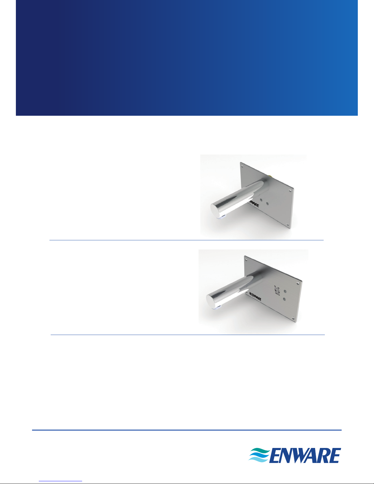
Wall Sensor Tap
Time Flow Stainless Steel Sensor Panel
Mains Powered with 205mm Spout
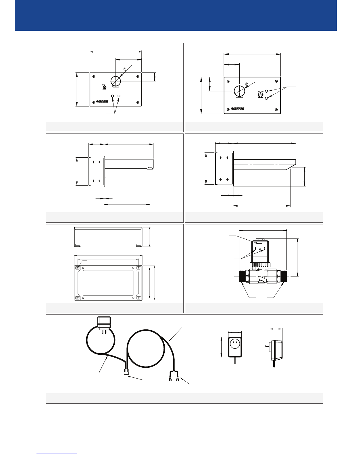
ENM5072-205
ENM5072-250
Wall Sensor Tap
Wave-On Wave-Off Stainless Steel Sensor Panel
Mains powered with 205mm or 250mm Spout
ENMATIC 5000 SERIES
WALL SENSOR TAP HANDS FREE
Call 1300 369 273
www.enware.com.au
Enware Australia Pty Limited
9 Endeavour Rd Caringbah NSW 2229 Australia
Ph: +61 2 8556 4000 Fax: +61 2 8556 4055

2 Call 1300 369 273 www.enware.com.au
TIME FLOW MODEL (ENM5071):
The tap will run for a set period of me, regardless
of further hand movement. The ow me is
factory set to 6 seconds. This can be increased to
9, 12, or 15 seconds if required (see appendix –
Sensor Programs).
WAVE-ON WAVE-OFF MODEL (ENM5072):
Once the sensor is acvated, the valve will remain
open and water will ow unl the hand is again
passed in front of the sensor, closing the solenoid
valve. It is not necessary for the object to remain
in the beam for the unit to keep the valve open.
If the solenoid valve remains open for more than
45 seconds, the unit will me-out and close the
valve automacally. This is intended to conserve
water and prevent overows. The me-out period
can be adjusted to 15, 30, 45, or 60 seconds (see
appendix – Sensor Programs).
The Enmac Wall Sensor Tap is a sensor operated, hands-free tap that is installed onto walls above
sinks, basins or wash troughs. It operates by sensing a hand passing the front of the sensor unit.
The wall sensor tap kit comes standard with a sensor panel with a xed aerated spout, a 1/2” solenoid
valve, a sensor panel bracket, and a 24 AC volt power pack.
For ENM5072, choose either 205mm or 250mm spout.
PRODUCT DESCRIPTION
SENSOR PLATE & SPOUT
BRACKET
SOLENOID
TRANSFORMER
COMPONENTS:
www.enware.com.au Call 1300 369 273 3
57.5
10
100
26
130
200
180
110
85
22
33
16 55
10
5TYP
DEPTH)
SPACE FOR
CIRCUIT BOARD
(REQUIRES 30mm
COVER PLATE
OUTLINE
200
130
100
33
40
SENSOR
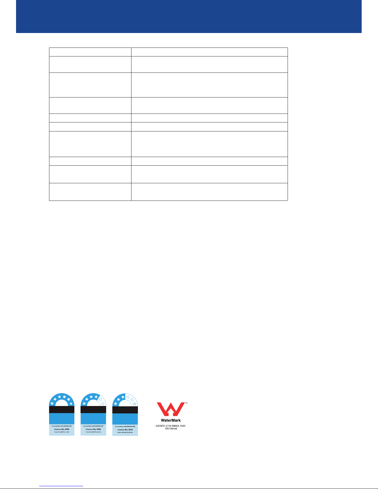
ENM5071 Front View
57.5
10
100
26
130
200
180
110
85
22
33
16 55
10
5TYP
DEPTH)
SPACE FOR
CIRCUIT BOARD
(REQUIRES 30mm
COVER PLATE
OUTLINE
193
208
3
65
120
ENM5071-205 Side View
57.5
10
100
26
130
200
180
110
85
22
33
16 55
10
5TYP
DEPTH)
SPACE FOR
CIRCUIT BOARD
(REQUIRES 30mm
COVER PLATE
OUTLINE
190
170
100
M4 Tapped Hole
115
65
Bracket
57.5
10
100
26
130
200
180
110
85
22
33
16 55
10
5TYP
DEPTH)
SPACE FOR
CIRCUIT BOARD
(REQUIRES 30mm
COVER PLATE
OUTLINE
59
88
58
2 m LONG
CABLE
SPADE
CONNECTORS
TO SOLENOID
3 PIN FEMALE
CONNECTOR
TO SENSOR
2 m LONG
CABLE
EMS805 Transformer
57.5
10
100
26
130
200
180
110
85
22
33
16 55
10
5TYP
DEPTH)
SPACE FOR
CIRCUIT BOARD
(REQUIRES 30mm
COVER PLATE
OUTLINE
200
130
55
40
50
SENSOR
ENM5072 Front View
57.5
10
100
26
130
200
180
110
85
22
33
16 55
10
5TYP
DEPTH)
SPACE FOR
CIRCUIT BOARD
(REQUIRES 30mm
COVER PLATE
OUTLINE
65 233
3
120
213
70
ENM5072-250 Side View
57.5
10
100
26
130
200
180
110
85
22
33
16 55
10
5TYP
DEPTH)
SPACE FOR
CIRCUIT BOARD
(REQUIRES 30mm
COVER PLATE
OUTLINE
70
90
SPADE
CONNECTORS
FOR GROUND
1/2" BSP
EMS804 Solenoid
DIMENSIONS (not to scale)
4 Call 1300 369 273 www.enware.com.au
TECHNICAL DATA
Inlet Connection 15 mm (1/2”) BSP
Recommended Working Pres-
sure 100 - 500 kPa*
Flow Rate 4 star (7.7 lpm)water efficiency rating supplied standard.
6 Star (5.6 lpm) or 3 star (9.1 lpm) WELS ratings available on
request
Maximum Hot Water Supply
Temperature 70°C^
Operating Voltage 24V AC
Power Consumption Less than 9W
Cable Lengths Transformer with 2m Lead to Sensor,
1.8m Lead from Sensor to Solenoid
Sensor Cable Length 0.1m
Sensor Functions Wave-On Wave-off, Time flow
Time-out settings for
Wave-On Wave-Off
15, 30, 45, 60 seconds
(Factory set at 45 sec)
Run time settings for Time
Flow
6, 9, 12, 15 seconds
(Factory set at 6 sec)
a) 45°C for healthcare and aged care buildings,
early childhood centres, primary and secondary
schools and nursing homes, or similar facilies
for the aged, the sick, children, or people with
disabilies; and
b) 50°C for all other situaons
(Laundries and kitchen sinks are not required to
have heated water at a maximum of 50°C)
*Enware products are to be installed in accordance with the Plumbing Code of Australia (PCA) and
AS/NZS3500. Installaons not complying with PCA and AS/NZS 3500 may void the product and
performance warranty provisions.
Reference should also be made to the Australasian Health facility Guidelines (AHFG), ABCB and Local
Government regulaons when considering the choice of, and the installaon of these products.
^ All heated water installaons for sanitary xtures used primarily for personal hygiene purposes shall
deliver heated water at a temperature not exceeding:
This product must be installed and commissioned by a qualied plumber.
For use with potable water only.
NOTE: Enware Australia advises:
1. Due to ongoing Research and Development, specicaons may change without noce.
2. Component specicaons may change on some export models.
The more
stars the more
water efficient
6litres per
minute
WATER RATING
www.waterrating.gov.au
The more
stars the more
water efficient
8litres per
minute
WATER RATING
www.waterrating.gov.au
The more
stars the more
water efficient
9.5
litres per
minute
WATER RATING
www.waterrating.gov.au

www.enware.com.au Call 1300 369 273 5
INSTALLATION
BEFORE PROCEEDING WITH INSTALLATION
SELECT THE LOCATION OF THE SENSOR
When selecng a locaon to install the
wall-mounted sensor, consider the following:
• Ease of operaon
• Water splash / water drips
• Passing trac
Be sure that passing trac cannot trigger
the sensor. Allow at least 400mm clearance
between sensor and passing trac.
• Obstrucons
Ensure that nothing is within range of the
sensor. Any obstrucon directly in front of, and
within possible range of, the sensor can trigger
the sensor randomly or constantly turn it on.
• Reecons and Lighng
If the sensor unit is installed into a locaon
where a nearby wall or object is reecng
the Infrared light back, the unit is eecvely
blinded and will not operate. Up to 600mm
clearance may be necessary from reecve
surfaces, such as ceramic les and stainless
steel, directly in front of, and parallel to, the
front face of the sensor. Any bright lighng
reecng o a highly reecve surface such
as a stainless steel sink, or a high visibility
reecve vest, may also interfere with correct
sensor operaon.
SET-OUT HEIGHTS
Suggested heights from nished oor:
Spout Oulet 1050 mm
1120mm to point of water
discharge
(Australasian Health Facility
Guidelines)
Top of
Basin
850 mm
865mm (Australasian Health
Facility Guidelines)
800 - 830mm
(refrerence: AS1428.1-2009)

6 Call 1300 369 273 www.enware.com.au
INSTALLATION
ACCESS TO SENSOR TAP COMPONENTS:
Ensure that access to the sensor, solenoid valve
and power pack/240 V power point is available
for future maintenance when planning or
installing assemblies.
• The solenoid valve and power point/ power
pack is generally located either in the ceiling
space or in the wall but they must be easily
accessible for servicing purposes. This may be
through an access panel in the ceiling or on
the wall.
• The cable should be located inside the wall
cavity to connect to the power pack lead. All
wiring, cables, or leads must be installed in
such a way that they can be easily removed
and replaced if necessary. It is recommended
that all cabling is fed through a minimum
of 25mm conduit to allow for servicing and
replacement in future.
BEFORE CONNECTING WATER SUPPLY
• Ensure all supply lines are ushed thoroughly
to remove debris prior to the installaon
of this product. Strainers (40 mesh) are
recommended if debris is an ongoing problem.
• A Pressure reducon valve may be required
to comply with the recommended maximum
supply pressure and/ or balanced pressure
requirements.
• Isolaon valve and mesh strainer should be
ed before the solenoid, for ease of servicing
and trouble-free solenoid operaon.
WATER SUPPLY TEMPERATURE
• As the sensor controls a single solenoid valve it
is necessary that water temperature and ow
must be pre-set to the unit. It is recommended
that an Aquablend Thermostac Mixing Valve
is used to provide pre-mixed water to the
valve.
WARNING:
Do not cut the wires or extend the
exisng leads without using the correct
lead extension from Enware, as this will
void warranty.

www.enware.com.au Call 1300 369 273 7
INSTALLING THE SOLENOID
The solenoid valve is installed into the water
supply line before the outlet spout. Quick-
connect ngs or unions should be ed on
either end of the solenoid, and an isolaon valve
and a mesh strainer should be ed before the
solenoid, for ease of servicing and trouble-free
solenoid operaon.
Note: Ensure the solenoid is installed in the
correct direcon. The arrow on the solenoid
body must align with the direcon of water
ow.
Connect the exible inlet hose for the spout to
the outlet of the solenoid.
INSTALLING THE SENSOR BRACKET
Once the posion of the sensor is determined,
x the sensor mounng bracket inside wall. Take
note of the maximum and minimum wall depths
for the sensor.
Before the wall is sheeted or nished, allow for
a cut out in the nished wall surface, of 193mm
wide x 115mm high rectangular hole.
Wall Depth
Minimum wall depth 65mm, maximum 80mm.
Wall Cut Out Dimensions
193mm wide x 115mm high rectangular hole in
wall, at least 65mm deep to allow for installaon
of bracket.
INSTALLATION
57.5
10
100
26
130
200
180
110
85
22
33
16 55
10
5TYP
DEPTH)
SPACE FOR
CIRCUIT BOARD
(REQUIRES 30mm
COVER PLATE
OUTLINE
Installing the sensor bracket
115
193
WALL CUT OUT
57.5
10
100
26
130
200
180
110
85
22
33
16 55
10
5TYP
DEPTH)
SPACE FOR
CIRCUIT BOARD
(REQUIRES 30mm
COVER PLATE
OUTLINE
Ensure the solenoid is installed in the correct
direcon

8 Call 1300 369 273 www.enware.com.au
WIRING METHOD
INSTALLATION
2 m LENGTH WIRE
SPADE CONNECTORS-
CONNECT TO SOLENOID
3 PIN FEMALE CONNECTOR
CONNECT TO SENSOR PLATE
3 PIN MALE CONNECTOR
CONNECT TO POWER BACK
FOR GROUND
2m LENGTH WIRE
Connect
here
Connect
here
Earth Connection
NOT USED
57.5
10
100
26
130
200
180
110
85
22
33
16 55
10
5TYP
DEPTH)
SPACE FOR
CIRCUIT BOARD
(REQUIRES 30mm
COVER PLATE
OUTLINE
Solenoid Connecon
POWER PACK AND CABLES
It is recommended that all cabling is fed
through 25mm conduit to make servicing and
replacement easier. The solenoid valve and
power point/ power pack is generally located
either in the ceiling space or in the wall but must
be easily accessible for servicing purposes. This
may be through an access panel on the wall or
ceiling.
The power pack has a 2 metre lead to the sensor
and 1.8 metre lead from the sensor to the
solenoid. Addional lead lengths up to 6 metres
can be accommodated with extension cables
(available separately from Enware).
Plug the 24V AC power pack into the 240V AC
power point.
WARNING: Protecng from Water Spray
Note that the power pack and connecons
are NOT spray or water proof. If water may
come into contact with any of the electrical
components or connecons (e.g. if electrical
components are exposed underneath a basin),
the unit and all of the interconnecons should
be installed into a water-proof enclosure.
WARNING:
Do not cut the electrical cable
of the sensor tap, or alter the
product in any way to suit
installaon. Damage caused
in this way will void warranty.
Cable extensions are available if
extra cable length is required.
(Refer to Spare Parts Secon)

www.enware.com.au Call 1300 369 273 9
INSTALLATION
AFTER THE WALL IS FINISHED ...
MOUNTING THE SENSOR PLATE
The stainless steel sensor unit is always mounted
ush to the wall. Feed the power pack cable
through the conduit and make the connecon
to the sensor by joining the line plug and socket,
observing the polarity of the plug.
Connect exible inlet hose for the spout to
solenoid again, turn on water and test for leaks.
Test the tap again for correct operaon.
Important:
Before xing the plate in place, apply a bead of
silicon sealant across the top of the plate and
down the sides to prevent moisture geng
between the wall face and the plate.
Fix the sensor panel using four screws provided.
Take care not to put hands in front of the lens
when mounng the plate, as the tap is now
operaonal and will acvate.
TESTING
Turn on the power to the unit and test the unit.
Wave-On Wave-O Model: Wave the back of
your hand through the beam to turn the water
on, and again to turn the water o.
Time-Flow: Simply place your hand in front of
sensor, and acvate the sensor.
For more details on sensor funcons, refer to
“Sensor Program”.
WARNING:
Sensor components are fragile and
sensive. Do not force the sensor
plate to t onto wall, or aempt to
disassemble sensor components, as this
could result in damage to sensor.
TESTING
Turn the water on, and check for leaks.
Connect all electrical components together temporarily, turn the power on and test the tap.
Once correct operaon of the tap is conrmed, disconnect the sensor plate cable and turn o the
power to the transformer. Turn water o at the isolaon valve and disconnect the spout & sensor
plate. The tap is now ready for sheeng or nishing of the wall.
10 Call 1300 369 273 www.enware.com.au
TROUBLESHOOTING
Sensor - Stainless Steel Face Plate and Sensor Time-Flow (6 Sec Default) suit ENM5071) ENMS134
Sensor - Stainless Steel Face Plate and Sensor Wave-On-Wave-O (suit ENM5072) ENMS133
Solenoid 1/2” EMS804
Transformer Input 240V output 24V 1 Amp with 2m Lead EMS805
2m Extension Cable (transformer to sensor) EMS840
4m Extension Cable (transformer to sensor) EMS841
4m Solenoid Extension Lead (Sensor to Solenoid) – Spade connecons EMS813
Solenoid service kit (1/2” AC) ENMS229
Spout Aerator (8 Lpm, Standard M22 -1) SP301
Fixing screw for sensor plate (Security M4x25 CSK Screw) 672480
Spout base O-ring (BS 119) 672352
“-205” Spout Only SPC203
“-250” Spout Only SPC250
SPARE PARTS
PROBLEM CAUSE RECTIFICATION
Tap/Water connues to ow
when power to tap (power
point) is both o or on
Solenoid valve is installed the wrong
way round. Check the direcon of
water ow is with arrow
Re install valve correctly
Debris in solenoid valve
Port hole in solenoid diaphragm is
blocked
Take solenoid apart and clean debris
from plunger or diaphragm
Solenoid diaphragm is damaged Replace solenoid diaphragm with
service kit
Warer supply pressure is too low check dynamic water pressure is at
least 100 kPa
Tap/Water turns on by itself Sensor is picking up reecons or
movement
Relocate sensor away from object/
movement
Tap/Water connues to ow
but only when power is on
Sensor is damaged by water or
incorrect cleaning
Replace sensor and recfy sealing
or cleaning methods
Tap/Water does not turn on
when hand is waved in front of
sensor.
Water supply is o or Thermostac
mixing valve has shut down
Check water supply and TMV
Solenoid valve is damaged Replace solenoid valve
Power supply is o or Power pack is
damaged
Turn power on or replace power
pack
Sensor is damaged Replace sensor
Water only turns on somemes Sensor has become
de-sensised
Replace sensor
Sensor acvates randomly Faulty or ickering lighng is
interfering with sensor beam
Repair faulty or ickering light
www.enware.com.au Call 1300 369 273 11
SERVICE & MAINTENANCE
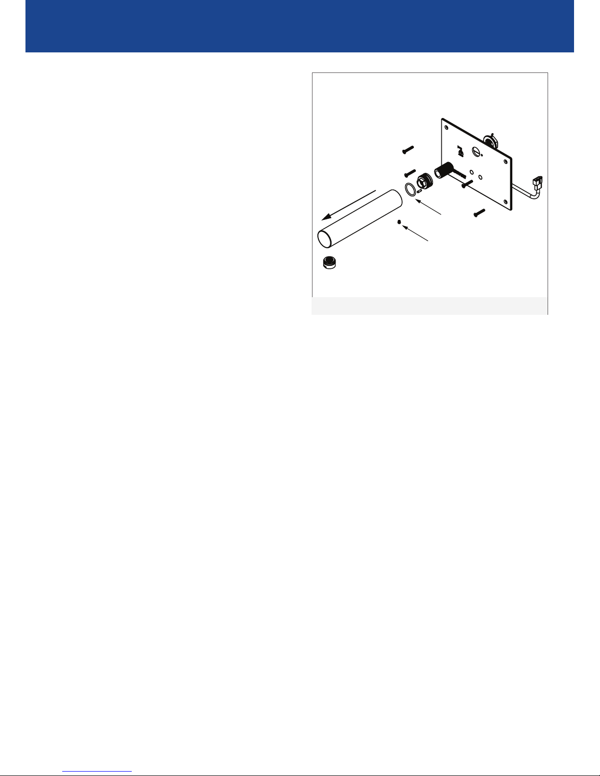
SERVICING THE SPOUT
1. Switch o power to sensor plate
2. Loosen the grub screw located at the boom of
the spout, then pull the spout o
3. Check the base o-ring, replace if worn. Lightly
grease the o-ring with a silicon based, potable
water approved grease (e.g. Molykote 111) then
place the o-ring back onto the base body
4. Check the locking pin posion and slide the spout
back onto the base body. Lock the spout in place
using the grub screw
IMAGE 7
SERVICING THE SENSOR
The sensor is a non serviceable component. If the
sensor is malfunconing, the enre sensor plate will
need to be replaced.
REPLACING THE POWERPACK
The powerpack is a non serviceable component. If
damaged, the powerpack must be replaced.
CLEANING
Enware Product should be cleaned with a so damp
cloth using only mild liquid detergent or soap and
water. Do not use cleaning agents containing a
corrosive acid, scouring agent or solvent chemicals.
Do not use cream cleaners, as they are abrasive.
Epoxy coated surfaces should only be cleaned with
a cloth and clear water or mild detergent. Use of
unsuitable cleaning agents may damage the surface.
Any damage caused in this way will not be covered
by warranty.
GRUB SCREW
BASE O-RING
57.5
10
100
26
130
200
180
110
85
22
33
16 55
10
5TYP
DEPTH)
SPACE FOR
CIRCUIT BOARD
(REQUIRES 30mm
COVER PLATE
OUTLINE
IMAGE 7
12 Call 1300 369 273 www.enware.com.au
SERVICE & MAINTENANCE
SOLENOID MAINTENANCE
For long periods of non-use, a minimum acvaon of
1-2 mes per day is recommended.
High frequency of use and high water supply pressures
reduce the service life of a solenoid.
If the solenoid is not working correctly or leaking, go
through the following steps to service the solenoid.
The most common cause of solenoid malfuncon is
debris being caught inside, in which case the solenoid
needs to be dismantled and cleaned. Service kits
including replacement diaphragms are available.
To Access the Solenoid Valve
1. Turn water supply o and acvate the sensor to
drain as much water from the ng as possible. Turn
power o to the sensor.
2. In most cases it is easier to remove the solenoid
valve completely from the installaon to service it.
Remove the electrical connectors from the solenoid
terminals, undo the water connecons on both the
water inlet and outlet of the solenoid, and remove
the solenoid.
3. The solenoid can be disassembled and checked for
debris or damage to the diaphragm. Refer to the
instrucons below for “Servicing the Solenoid”. Take
note of the locaon of the components so that it can
be reassembled in the correct order.
4. Service or replace the solenoid and re-install into
the line. Push the cable connectors back onto the
solenoid terminals
5. Turn power on and test tap.
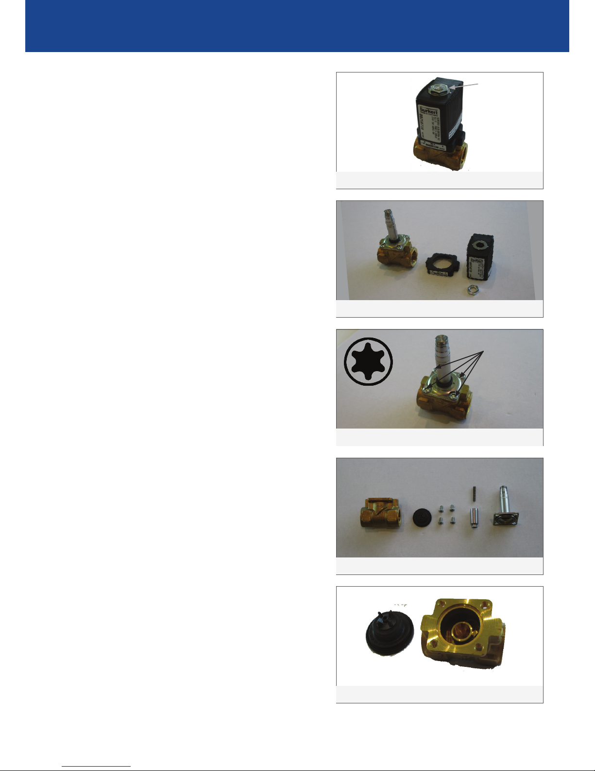
Servicing the Solenoid
Tools required: Spanner, T20 Torx Bit
1. Remove the nut located on top of the solenoid.
SEE IMAGE 8
2. Remove the black coil body and plasc cover from
the core tube. SEE IMAGE 9
3. Using a T20 Torx screw driver (star bit), remove the
4 Torx screws that are holding the core tube. Use the
correct size tool and take care not to round the screws
heads. Keeping in mind that the plunger inside the
core tube is spring loaded, dismantle the valve with
care. Take note of the order of parts assembled. SEE
IMAGES 10, 11, 12
4. Check seat and diaphragm for debris or any damage.
SEE IMAGE 12
57.5
10
100
26
130
200
180
110
85
22
33
16 55
10
5TYP
DEPTH)
SPACE FOR
CIRCUIT BOARD
(REQUIRES 30mm
COVER PLATE
OUTLINE
IMAGE 9
57.5
10
100
26
130
200
180
110
85
22
33
16 55
10
5TYP
DEPTH)
SPACE FOR
CIRCUIT BOARD
(REQUIRES 30mm
COVER PLATE
OUTLINE
IMAGE 8
NUT
57.5
10
100
26
130
200
180
110
85
22
33
16 55
10
5TYP
DEPTH)
SPACE FOR
CIRCUIT BOARD
(REQUIRES 30mm
COVER PLATE
OUTLINE
IMAGE 10
T20 TORX
4 X TORX
(T20)
SCREWS
57.5
10
100
26
130
200
180
110
85
22
33
16 55
10
5TYP
DEPTH)
SPACE FOR
CIRCUIT BOARD
(REQUIRES 30mm
COVER PLATE
OUTLINE
IMAGE 11
57.5
10
100
26
130
200
180
110
85
22
33
16 55
10
5TYP
DEPTH)
SPACE FOR
CIRCUIT BOARD
(REQUIRES 30mm
COVER PLATE
OUTLINE
IMAGE 12
www.enware.com.au Call 1300 369 273 13
SERVICE & MAINTENANCE
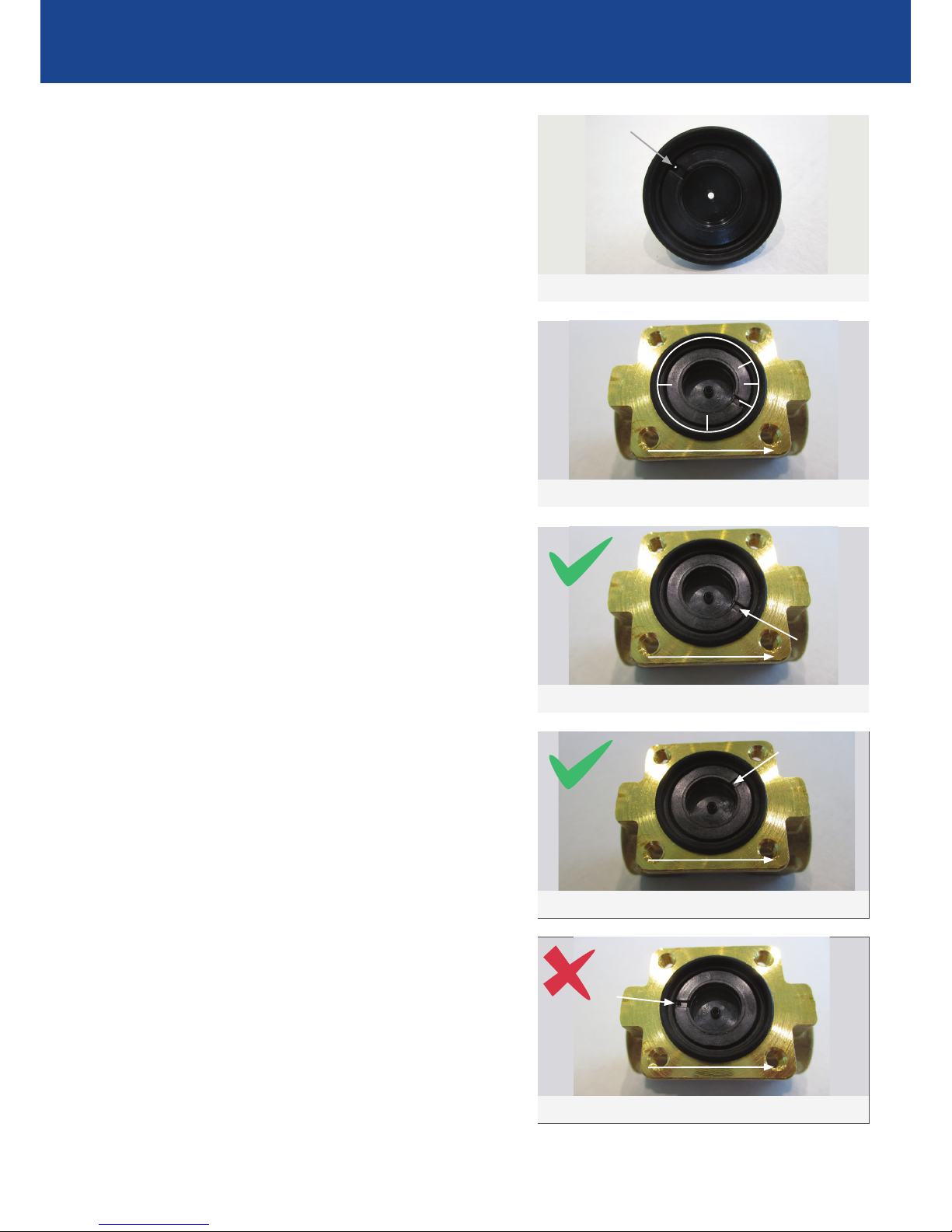
5. Note the small hole in the rubber diaphragm.
It is important that this hole is clear and not
obstructed by debris. Clean the diaphragm by
rinsing with water. SEE IMAGE 13
6. Replace any component that is damaged. (Service
Kit code ENMS229)
7. To reassemble, rstly place the rubber diaphragm
in correct posion. The hole in the diaphragm
should be assembled either at 2 O’clock or 4
O’clock posion, when the direcon of ow is
going from le to right, as shown below. The
arrow is indicated on the solenoid body. SEE
IMAGES 14-17
Note: Do not apply grease to internal components
of solenoid. Grease can deteriorate over me and
cause the solenoid to malfuncon.
8. Reassemble the plunger with spring into the core
tube. Check that the spring is reassembled back
together inside the core tube, and no foreign
material is in the core tube to restrict the plunger
movement.
9. Once this is done, place the core tube back on top
of the valve and ghten back up with the 4 Torx
screws.
10. Once the core tube is ghtened, place the plasc
cover which goes over the core tube. This covers
the screws. When doing so, please ensure the
scker on the plasc has the same ow direcon
as the body.
11. Finally place the black coil body back over the
core tube, and ghten the nut back up.
57.5
10
100
26
130
200
180
110
85
22
33
16 55
10
5TYP
DEPTH)
SPACE FOR
CIRCUIT BOARD
(REQUIRES 30mm
COVER PLATE
OUTLINE
IMAGE 14
57.5
10
100
26
130
200
180
110
85
22
33
16 55
10
5TYP
DEPTH)
SPACE FOR
CIRCUIT BOARD
(REQUIRES 30mm
COVER PLATE
OUTLINE
IMAGE 13
HOLE
57.5
10
100
26
130
200
180
110
85
22
33
16 55
10
5TYP
DEPTH)
SPACE FOR
CIRCUIT BOARD
(REQUIRES 30mm
COVER PLATE
OUTLINE
IMAGE 15
2 O’CLOCK
4 O’CLOCK
DIRECTION OF FLOW
DIRECTION OF FLOW
57.5
10
100
26
130
200
180
110
85
22
33
16 55
10
5TYP
DEPTH)
SPACE FOR
CIRCUIT BOARD
(REQUIRES 30mm
COVER PLATE
OUTLINE
IMAGE 16
57.5
10
100
26
130
200
180
110
85
22
33
16 55
10
5TYP
DEPTH)
SPACE FOR
CIRCUIT BOARD
(REQUIRES 30mm
COVER PLATE
OUTLINE
IMAGE 17
DIRECTION OF FLOW
DIRECTION OF FLOW

14 Call 1300 369 273 www.enware.com.au
SENSOR PROGRAM
57.5
10
100
26
130
200
180
110
85
22
33
16 55
10
5TYP
DEPTH)
SPACE FOR
CIRCUIT BOARD
(REQUIRES 30mm
COVER PLATE
OUTLINE
IMAGE 18
Adjusng The Flow Time,
Sensor Range or Changing Sensor Funcons
1. To access the sensor program, rstly take the
sensor plate o the wall and disconnect the
power to the sensor.
2. On the back of the sensor, carefully prise
open the rubber grommet on the black plasc
protecve box. The program switches are
located inside the hole. Ensure no water drops
or moisture gets inside the protecve box.
3. The 6 switches on the sensor PCB can be turned
on or o according to the desired program. Refer
to the program table below. Use a precision
screwdriver or a similar small tool to turn the
switch. (Note: ENM5071 cannot be used as a
Wave-On Wave-O sensor, due to the locaon
of sensor being under the spout.)
4. Once the sensor program is set and tested, put
the rubber grommet back to cover the hole in
the black protecve box. Reconnect sensor to
power supply and install the sensor back onto
wall.

www.enware.com.au Call 1300 369 273 15
SENSOR PROGRAM
Note: The sensor range may vary depending on the light-reecng
characteriscs of the object in the sensor range.
Switch Switch Sensing Range Distance
OFF OFF 120mm approx. (Short)
ON OFF 140mm approx. (Medium-Short)
OFF ON 150mm approx. (Medium-Long)
ON ON 180mm approx. (Long)
SENSOR RANGE
Switch Switch Switch Switch Funcon
OFF OFF OFF OFF 15 sec Time Out, Wave-On Wave-O
OFF OFF ON OFF 30 sec Time Out, Wave-On Wave-O
OFF ON OFF OFF 45 sec Time Out, Wave-On Wave-O
OFF ON ON OFF 60 sec Time Out, Wave-On Wave-O
SENSOR FUNCTIONS
Wave-On Wave-O
Wave hand in front of sensor once to turn on,
Wave hand in front of sensor once to turn o.
Default me-out (maximum run me) seng from factory is 45 seconds for Wave-On Wave-O (EMW802,
EMW803, ENM5072).
Switch Switch Switch Switch Funcon
ON OFF OFF OFF 6 sec Flow Time, Time Flow
ON OFF ON OFF 9 sec Flow Time, Time Flow
ON ON OFF OFF 12 sec Flow Time, Time Flow
ON ON ON OFF 15 sec Flow Time, Time Flow
Time Flow
Put hand in front of sensor to turn on, the water ows for the set period of me, then turns o
automacally.
Water ows for the set period of me regardless of any further hand movement.
Default me seng from factory is 6 seconds for Time Flow (EMW804, ENM5071).

PRODUCT WARRANTY FOR AUSTRALIA Eecve 1 September 2014
Enware Australia Pty Limited (ACN 003 988 314)
(“we” or “us”) warrants that this product (also referred
to as “our goods”) will be free from all defects in
materials and workmanship for 12 months* from the
date of purchase. Our liability under this warranty is
limited at our opon to the repair or replacement of
the defecve product or part, the cost of repair of the
defecve product or part or the supply of an equivalent
product or part, in each case if we are sased the
loss or damage was due to a defect in the materials or
workmanship of the product or part. All products must
be installed in accordance with the manufacturer’s
instrucons, the PCA, and AS/NZS3500 including any
other applicable regulatory requirements.
exceptions
This warranty does not apply in respect of any damage or
loss due to or arising from:
a) Failure by you or any other person to follow any
instrucons for use (including instrucons and direcons
relang to the handling, storage, installaon, ng,
connecon, adjustment or repair of the product)
published or provided by us;
b) Failure by you or any other person responsible for the
ng, installaon or other work on the product to follow
or conform to applicable laws, standards and codes
(including the AS/NZ 3500 set of Standards, all applicable
State and Territory Plumbing Codes, the Plumbing Code
of Australia and direcons and requirements of local and
other statutory authories); or
c) Any act or circumstance beyond our control including
faulty installaon or connecon, accident, abnormal use,
acts of God, damage to buildings, other structures or
infrastructure and loss or damage during product transit
or transportaon.
making a claim
To make a claim under this warranty you must
nofy us in wring within 7 days of any alleged defect
in the product coming to your aenon and provide us
with proof of your purchase of the product together with
a completed Product ServiceRequest form (ENF091),
which is available on request from our oce or website
(see contact details below). All nocaons and
accompanying forms must be sent to us marked for the
aenon
of the Enware Australia Pty Limited, 9 Endeavour Road,
Caringbah NSW 2229. We can also be contacted by
telephone (1300 369 273) or by
email (inf[email protected]om.au). Your costs in making a
claim under this warranty, including all freight, collecon
and delivery costs, are to be borne and paid by you. We
also reserve the right at our cost
to inspect any alleged defect in the product wherever it
is located or installed or on our premises.
other conditions
Except as provided or referred to in this document, we
accept no other or further liability for any damages
or loss (including indirect, consequenal or economic
loss) and whether arising in contract, tort or otherwise.
Any benets available to you under this warranty are in
addion to any non-excludable rights or remedies you
may have under applicable legislaon, including as a
“consumer” under the Australian Consumer Law. To that
extent you need to be aware that: Our goods come with
guarantees that cannot be excluded under the Australian
Consumer Law. You are entled to a replacement or
refund for a major failure and for compensaon for any
other reasonably foreseeable loss or damage. You are
also entled to have the goods repaired or replaced if
the goods fail to be of acceptable quality and the failure
does not amount to a major failure.
* 1 Year parts and labour on the complete assembly.
Aer 1 year, a further 4 years parts only warranty is
applicable to sequenal valve cartridge.
Table of contents
Other enware Accessories manuals

Popular Accessories manuals by other brands

Airmar
Airmar WeatherStation 110WXS Owner's guide and installation manual

NTI
NTI SPLITMUX-DVI-4RT Installation and operation manual

Airzone
Airzone FLEXA 3.0 IBPRO6 Assembly instructions

Ningbo Pdlux Electronic Technology CO.,Ltd
Ningbo Pdlux Electronic Technology CO.,Ltd PD-V19 instructions

EL
EL EL-4601 quick start guide

MUBVIEW
MUBVIEW Bell-J9 quick start guide


