Magnetics that count
BOGEN Electronic GmbH · Potsdamer Straße 12-13 · 14163 Berlin · Germany
Fon +49 (0)30 81 00 02-0 · Fax +49 (0)30 81 00 02-60 · magnetics@bogen-electronic.com · www.bogen-electronic.com
IKS9 manual Rev 1.0 (2020/07/14)
3/7
Electromagnetic Compatibility
For the electrical connection it is essential that the
electromagnetic compatibility (EMC) is guaranteed.
• System and control cabinet must be connected to the
same ground potential.
• Use shielded cables. Connect the cabinet side of the
cable shield with protective earth (PE).
• Avoid installing in close proximity to power lines.
• The nominal operating voltage (see datasheet) must be
observed even if there is a voltage drop along the supply
line!
• Determine the place of installation so that inductive
and capacitive interferences cannot affect the sensor.
By adequately routing the cable, interferences can be
reduced.
Intended Use
The incremental magnetic sensing heads IKS9 are part
of a highly accurate measuring system consisting of
magnetic scales and sensing heads capable of contactless
position detection for linear and rotary applications.
Fields of deployment:
• mechanical engineering
• automation
• medical engineering
• electrical engineering.
The system consists of a sensing head and a linear
or rotating magnetic scale and can be incorporated
into various electronic systems. It can be configured
according to the customer‘s demands. In combination
with a suitable analysis software absolute and relati-
ve position and position changes can be measured. In
this way it is possible, for instance, to control machi-ne
tools, determine torsional forces or detect longitu-dinal
expansions.
Function and Properties
The incremental magnetic sensing heads IKS9 are
suitable for non-contact, incremental distance measuring
systems. The measuring function is realized by magnetic
scanning.
The system has the following features:
• non-contact, quick position measurement
• high reproducability
• programmable with PC
• freely programmable resolutions
• adjustable maximum output frequencies
• different connectors with adaptable cable lengths
• no wear from usage
• high gap tolerance
• resistant to dust, cooling lubricant emulsion, oil, etc.
• unlimited measuring distance.
Mode of operation
The sensing head with its sensor is mounted on the
machine part whose position is to be measured. The
measuring magnetic scale is mounted along the
measuring distance. On the magnetic scale alternating
magnetic north and south poles are positioned with
a regular distance. The magnetic AMR sensor cells
(anisotropic magnetoresistive effect) in the sensing head
are scanning the magnetic poles on the scale contact-
free.
Permissive travelling speed
See technical data sheet of the respective type on the
website: www.bogen-electronic.com/download
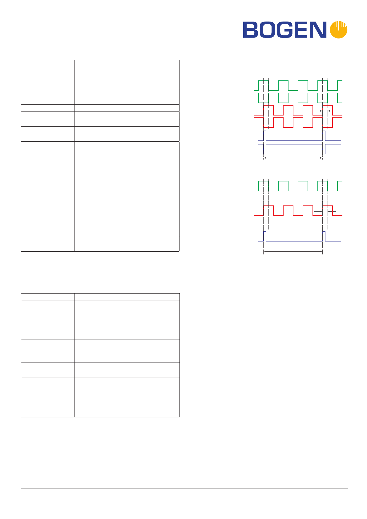
Digital output
The sensing head with digital output signals converts
the analog signals into a digital quadrature signal (A/B
pulses) and transmits them to the controller. The two
digital square wave signals A and B are electrically phase
shifted by 90°.
The sign of the phase shift indicates the direction of
movement of the sensing head. Every change of A or B
(rise to fall or vice versa) is a count for the incremental
counter (up/down counter). If signal A is in advance, the
counter increments. If signal B is in advance, the counter
decrements. The controller thus knows at all times the
position of the sensing head, without having to query the
sensor periodically (real-time capability).