EO Pro Hub Instruction sheet

© 2019 Juuce Ltd t/a EO Charging. All rights reserved.
EO Pro Hub Installation
Guidelines

EO Pro Hub Installation Guidelines
Page 2of 14
27 March 2019
Table of Contents
1 Introduction ....................................................................................................................................3
2 MID Meters –Physical Installation .................................................................................................4
2.1 Type of Meters........................................................................................................................4
2.2 Location of the MID Meter for the Site Supply.......................................................................5
2.3 Phase rotation.........................................................................................................................5
2.4 Serial Bus.................................................................................................................................6
3 MID Meters –Configuration...........................................................................................................7
3.1 Meter Operation.....................................................................................................................7
3.2 Entering configuration mode..................................................................................................7
3.3 Configuration setting of all MID Meters .................................................................................8
3.4 Additional settings for the site supply meter .........................................................................8
4 Installation of the Pro Hub............................................................................................................10
4.1 LEDs.......................................................................................................................................12
4.1.1 Start Up .........................................................................................................................12
4.1.2 Normal Operation.........................................................................................................12
5 EO Cloud Settings..........................................................................................................................13
6 Further Technical Support ............................................................................................................14
EO Pro Hub Installation Guidelines
Page 3of 14
27 March 2019
1Introduction
This document details the installation guidelines for the EO Pro Hub and associated Metering
Information Directive compliant electricity meters (MID Meters for short) if they are being used
on site. The MID meters are used to measure the current consumption by each of the charging
station and an additional meter for the measuring of the site’s current consumption.
This document details important information about how to wire up the hub and the appropriate
MID meters.
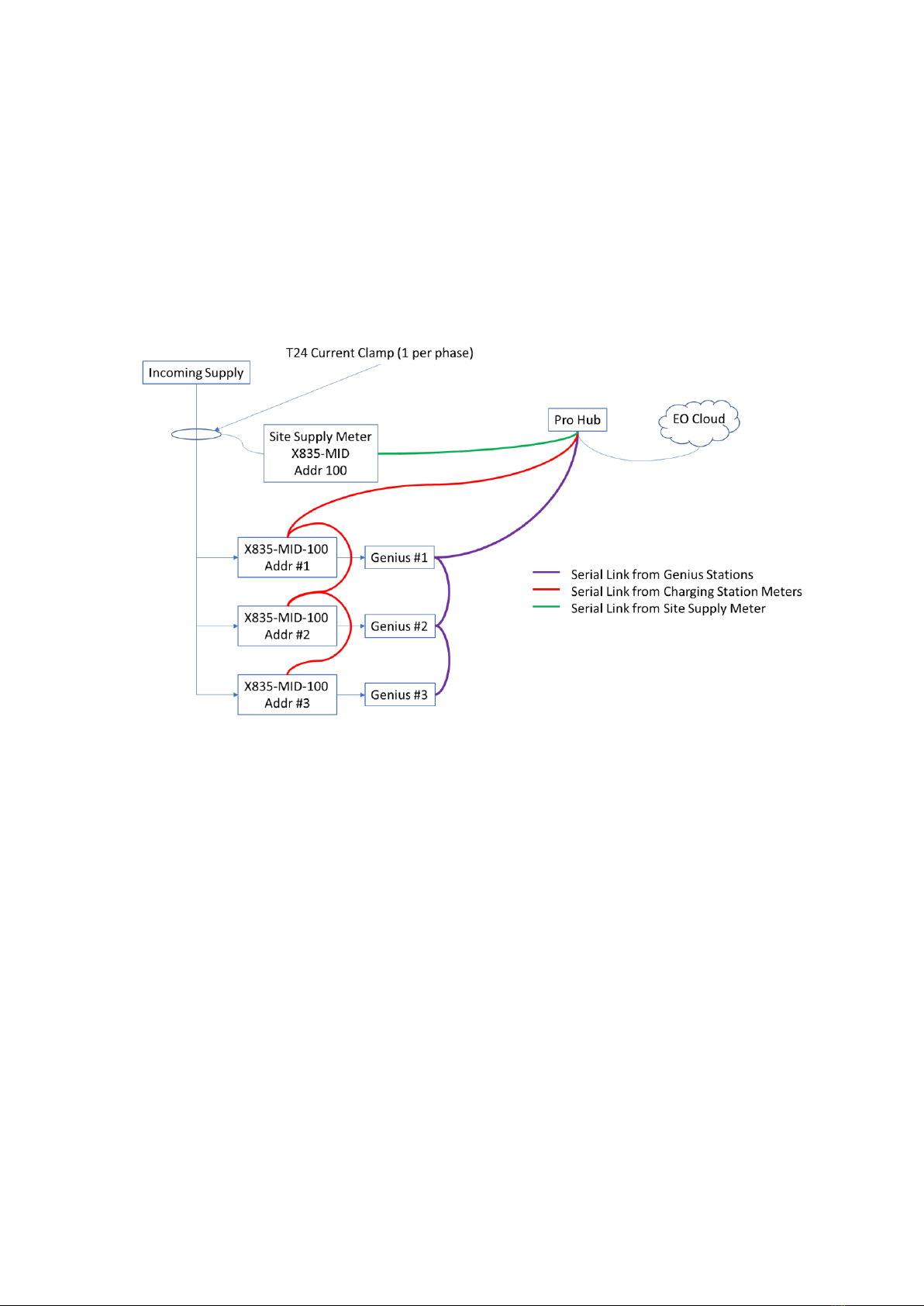
The basic overview of the installation is as follows:
Figure 1 - Overview of the Pro Hub installation
EO Pro Hub Installation Guidelines
Page 4of 14
27 March 2019
2MID Meters –Physical Installation
2.1 Type of Meters
The EO Pro Hub will work with the following meters
•Three phase meter for the charging stations
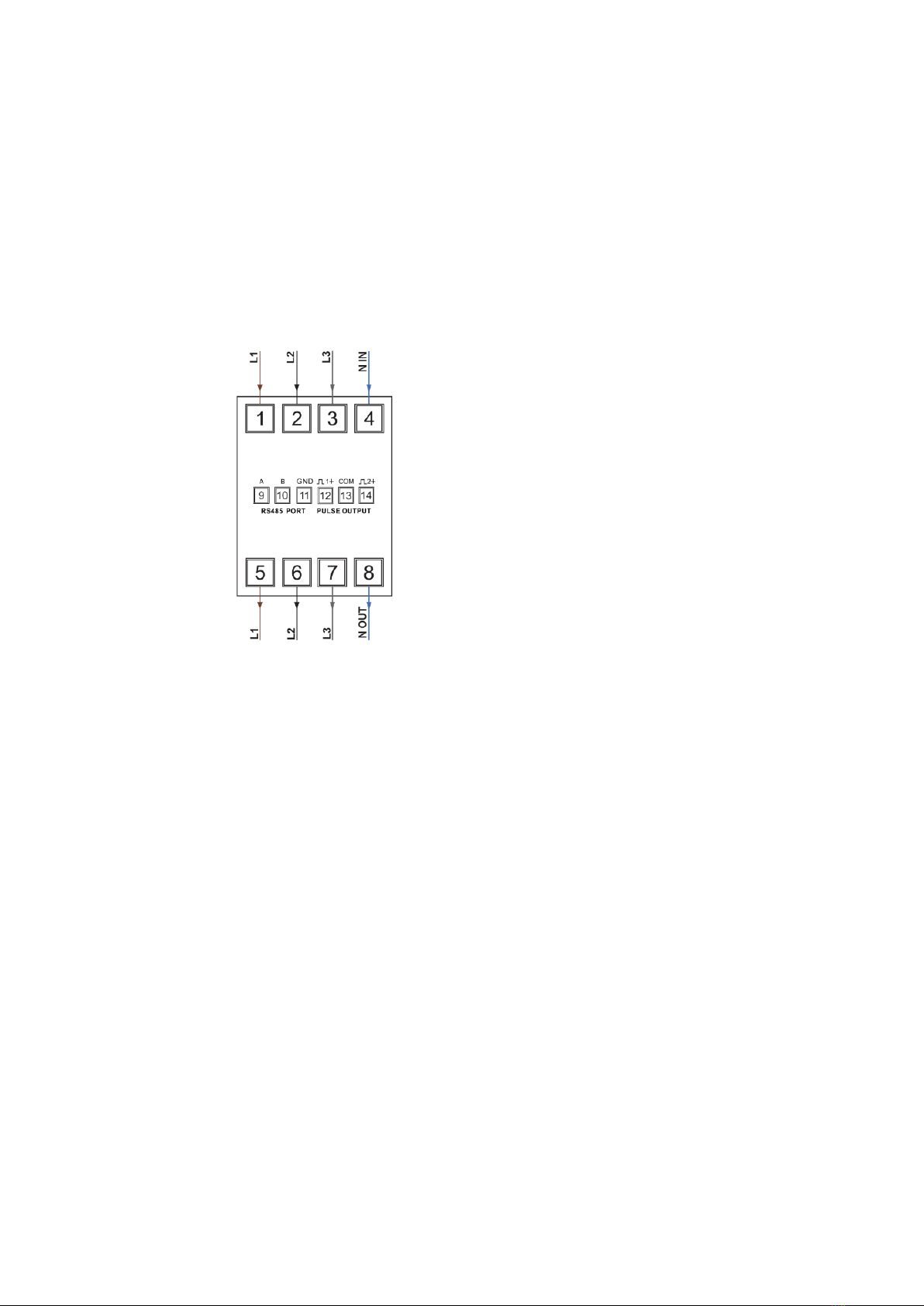
oSmartrail X835-100-MID SPC 1/5A CT Op SP/TP Multifunction
oThis is a direct connect meter
oThis meter is to be used for both single phase Genius stations and three phase
Genius stations (this is due to protocol issues)
oThis meter is 4 DIN wide
o
Figure 2 - Wiring Diagram for the X835-100-MID meter
•Three phase meter for the measurement of the site’s consumption which is required for
ALM
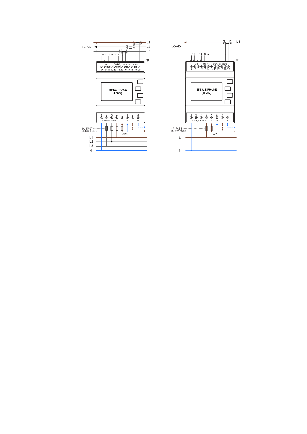
oSmartrail X835-MID SPC 1/5A CT Op SP/TP Multi
oThis meter uses CT Clamps for measuring the site’s current consumption
oThis meter is 4 DIN wide
EO Pro Hub Installation Guidelines
Page 5of 14
27 March 2019
o
Figure 3 - Wiring Diagram for X835-MID meter - 1Ph and 3Ph
•CT Clamps for measuring the site supply
oSmart Process T24 current core transformer
The wiring instructions for the MID meters are enclosed in the packaging of the MID meters.
2.2 Location of the MID Meter for the Site Supply
Due to the design of the meter it is important that the output of the T24 current clamps are fed
directly into the three phase MID meter. i.e. no extension cables
This is because if the cables are extended then the losses in the cable are too great and cause the
accuracy of the MID meter to drop. This must not happen for ALM to work correctly.
2.3 Phase rotation
It is important that the phase rotation of the station is taken into account when installing the
stations and meters.
The MID meter and EO Charging Station must be on the same phase rotation
This is so that accurate readings are returned and ALM can function correctly. Therefore the Phase
Rotation must occur before the MID meter. An example of the wiring is shown below:

EO Pro Hub Installation Guidelines
Page 6of 14
27 March 2019
Figure 4 - Location of the phase rotations
2.4 Serial Bus
Care needs to be taken over the serial bus connection between the meters and the EO Pro Hub. If
there is a meter measuring the site consumption for ALM then there needs to be two serial buses:
1) Serial Bus 1 –all MID Meters measuring the charging stations
2) Serial Bus 2 –MID for the site supply meter with the CT Clamps
EO Pro Hub Installation Guidelines
Page 7of 14
27 March 2019
3MID Meters –Configuration
When the MID meters have been installed and powered, then there are some software
configuration settings that need to be made to ensure that the EO Pro Hub can communicate
successfully to the MID Meters
3.1 Meter Operation
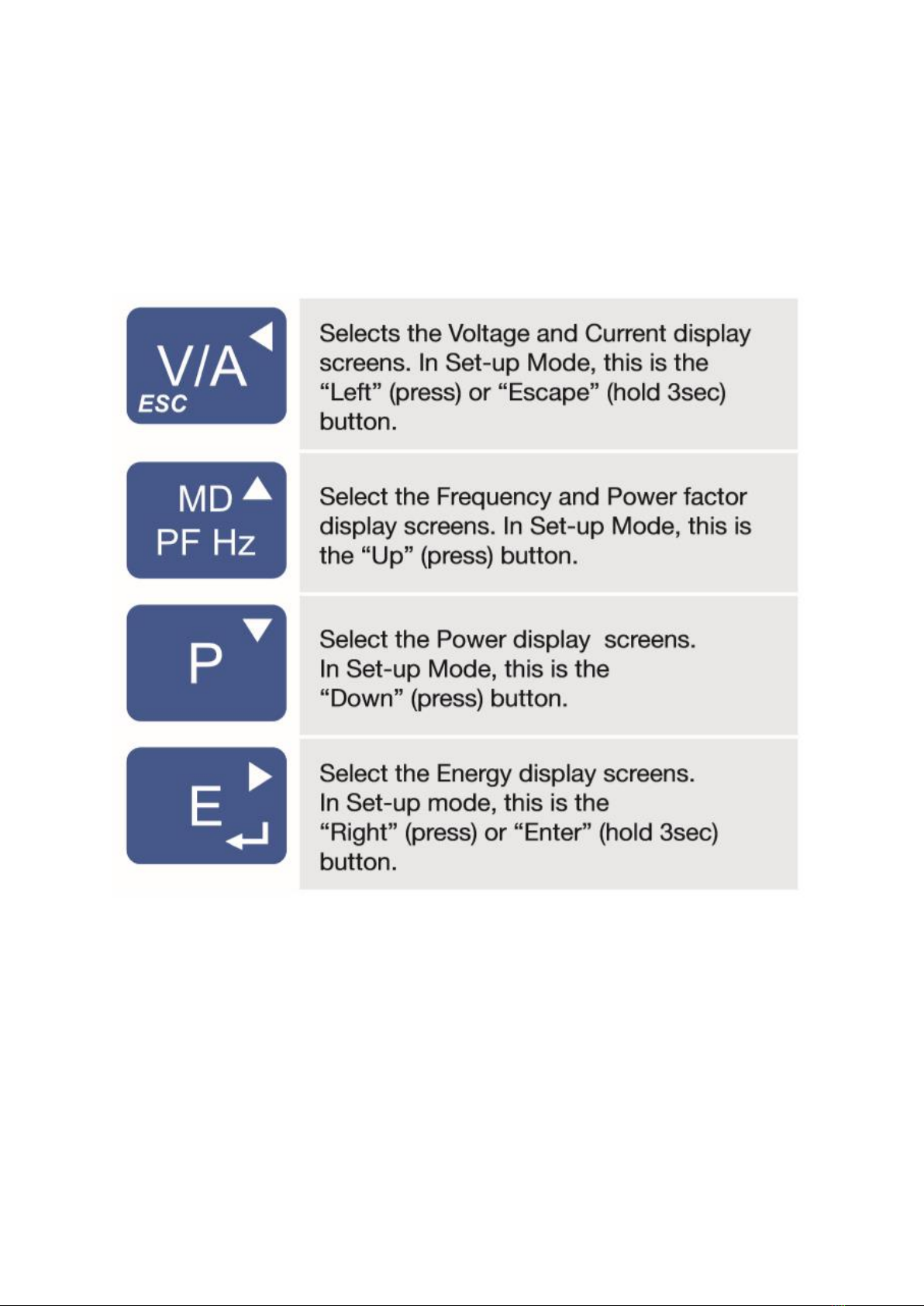
There are four buttons on the side of the meter which allow you to cycle through various Menus
Figure 5 - Description of Buttons on the MID Meter
3.2 Entering configuration mode
There is a config mode on the MID meters which needs to be entered before settings can be
changed:
1) Ensure the unit is powered
2) Press and hold the “E” button
3) Enter a pass code of 1000 (use the up, down and across arrows on the buttons)
4) Press and hold the “E” button
At this point the config mode shall be entered
EO Pro Hub Installation Guidelines
Page 8of 14
27 March 2019
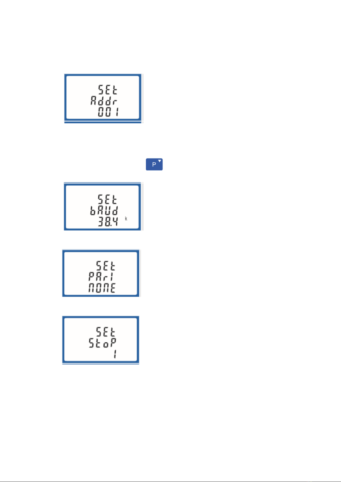
3.3 Configuration setting of all MID Meters
Whilst in the Meter config mode, the following parameters need to be set
1) Address
a. Site Supply Meter Address = 100
b. Station Meter address = a sequential number from 1 e.g. 1 (for station1), 2 (for
station 2), 3 (for station 3),….
c. The important number is that the site supply is always allocated to address 100
d. Pressing “Down Button” will take you to the next menu item
2) Baud Rate
a. 38.4K
3) Parity
a. None
4) Stop Bit
a. One
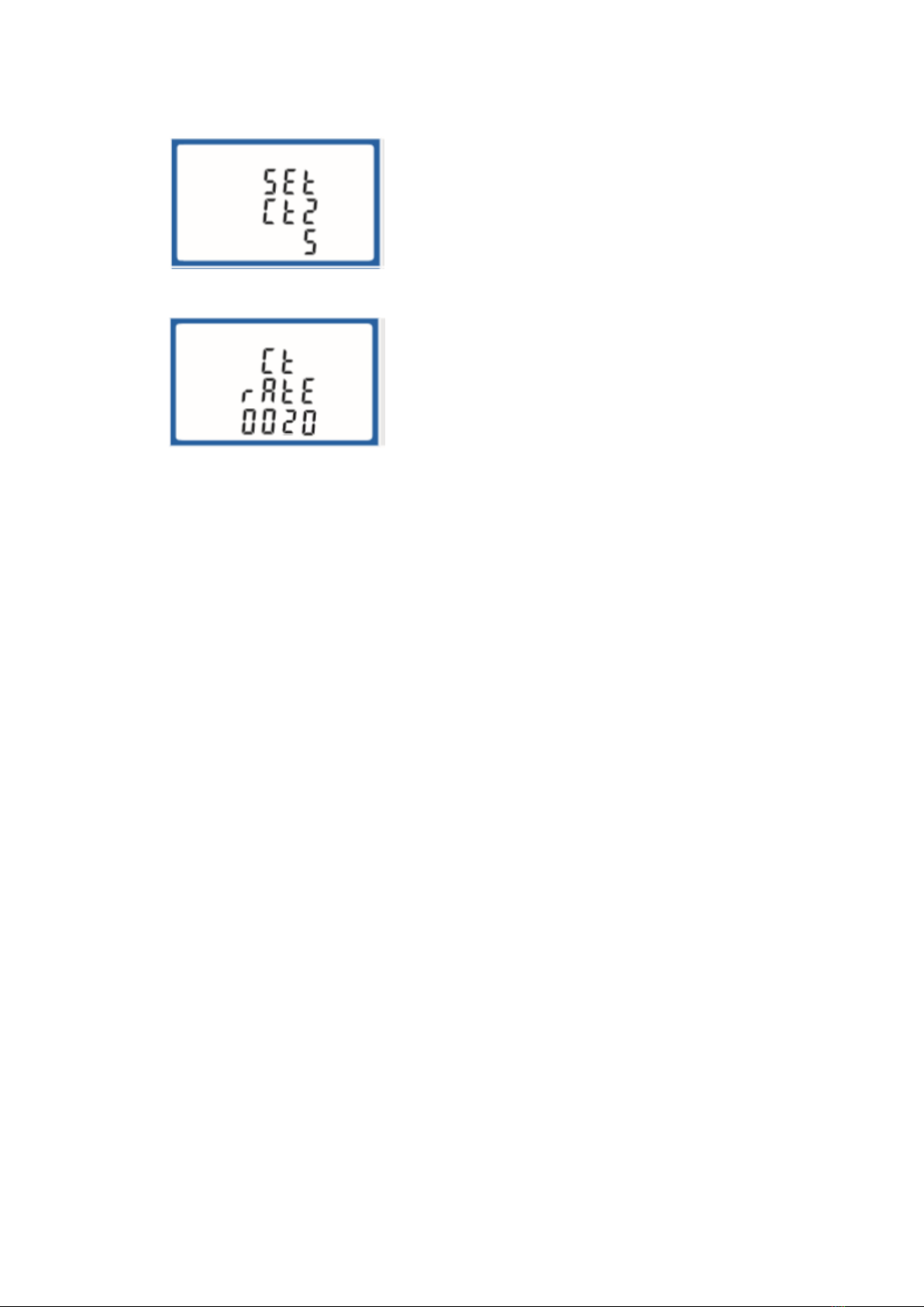
3.4 Additional settings for the site supply meter
The Site Supply meter with the CT Clamps has additional configuration settings which need to be
entered carefully as the options can only be entered once. These are the CT output current and the
CT rate. Both of these values depend on the CT clamp that has been installed and if the
recommended Smart Process T24 Current Clamps have been installed then set the following options
EO Pro Hub Installation Guidelines
Page 9of 14
27 March 2019
•CT 2 = 5
oThe output current is rated at 5 A
•CT Rate = 20
oThe rate is calculated by the input current divided by the output current. For the T24
clamp this rating is 100/5 = 20
EO Pro Hub Installation Guidelines
Page 10 of 14
27 March 2019
4Installation of the Pro Hub
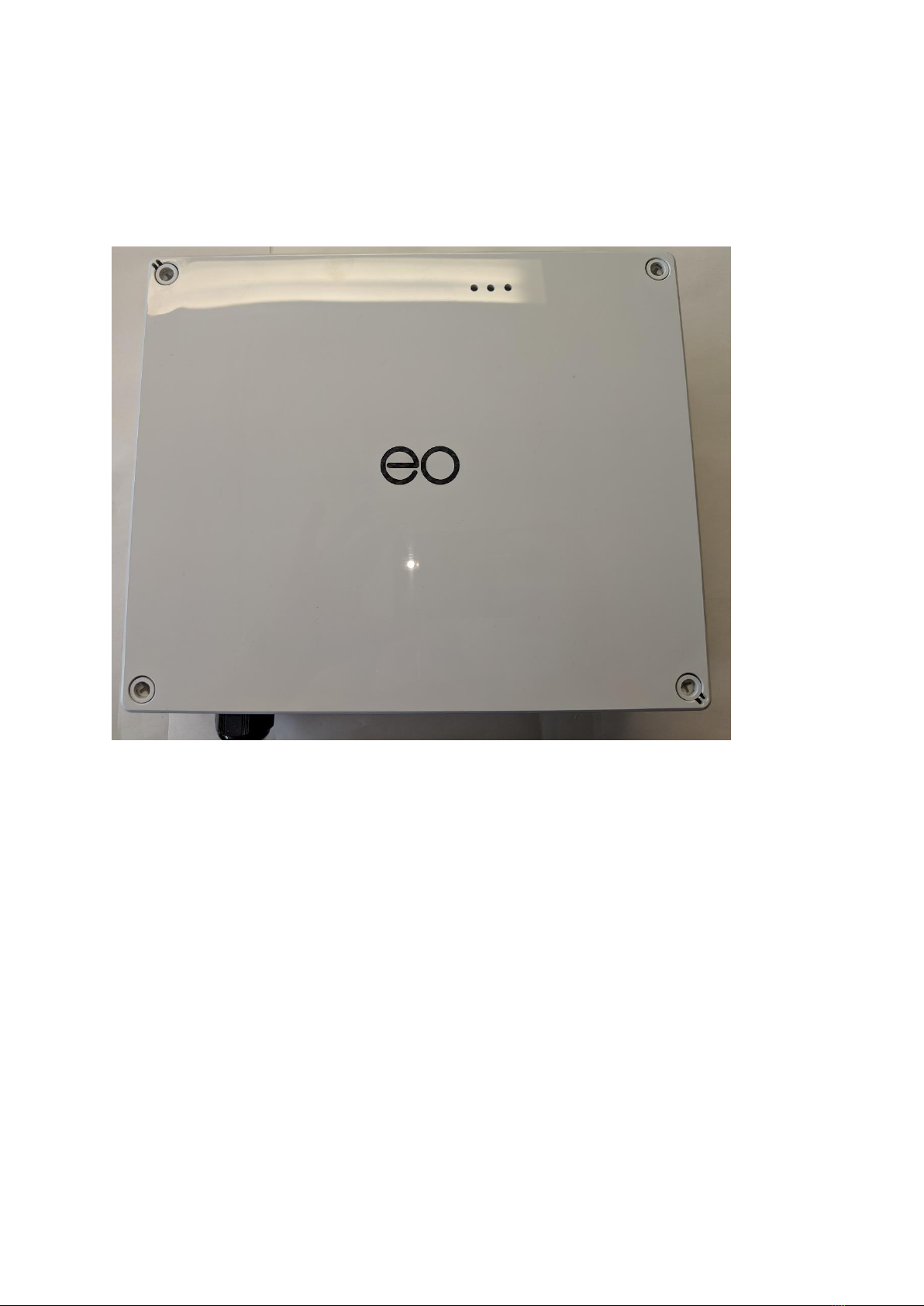
1) Mount the Pro Hub to the wall
a. Note that the Pro Hub is not weather proof due to the ventilation holes and so
therefore the hub should be mounted inside an appropriate cabinet
Figure 6 - Hub Pro with Cover
EO Pro Hub Installation Guidelines
Page 11 of 14
27 March 2019
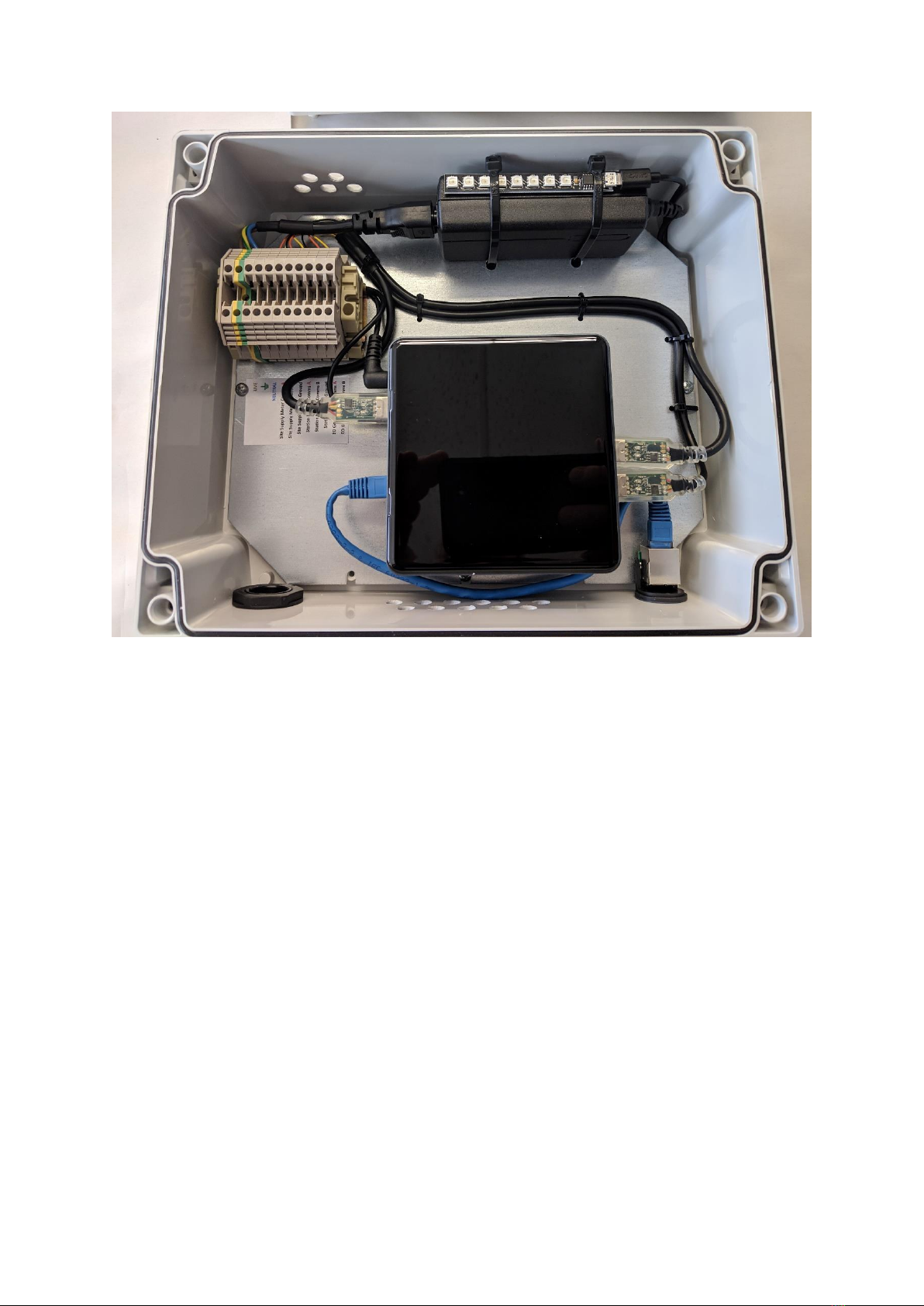
Figure 7 - Pro Hub with cover removed
2) Connect the inputs to the terminal rail
a. Terminal Stop
b. Live
c. Earth
d. Neutral
e. Site Supply Comms A - USB 1 –Orange
f. Site Supply Comms B - USB 1 –Yellow
g. Site Supply Comms GND - USB 1 –Black
h. Station Meters Comms A - USB 2 –Orange
i. Station Meters Comms B - USB 2 –Yellow
j. Station Meters Comms GND - USB 2 –Black
k. EO Genius Serial Comms A - USB 3 –Orange
l. EO Genius Serial Comms B - USB 3 –Yellow
m. Terminal Stop
3) Connect the Ethernet connection for access to the internet
4) Apply Power
When the power has been applied then the 3 USB to Serial adaptors shall start to flash green. This
will indicate that the communications has been wired up correctly.
Additionally there is a LED panel which displays the same LED sequence as the standard EO Hub. This
sequence is as follows:

EO Pro Hub Installation Guidelines
Page 12 of 14
27 March 2019
4.1 LEDs
There are three status LEDs on the EO Hub as shown. LED1 is on the far left, LED2 is in the middle
and LED3 is on the far right. These LEDs are either illuminated green or off. The LEDs indicate
different stages of operation with the principle stages being “Start Up” and “Normal Operation”
4.1.1 Start Up
Stage
LED1
LED2
LED3
Repeats
Description
1
6 times
Start Up
2
Solid
Error state –contact EO
3
2 Flashes
Connecting to primary server
4
2 Flashes
Connecting to Secondary server if primary
failed
5
6 times
Failure to Connect –Check Internet
connections
6
6 times
Start Up successful
7
5 times
Fatal Error –Contact EO
After a successful start up, then the EO Hub shall enter into Normal Operation.
4.1.2 Normal Operation
Stage
LED1
LED2
LED3
Repeats
Description
1
6 times
Secondary Start Up
2
Solid
Internet Connection Test
3
Solid
Configuring Hub –this can take up to 60sec
4
LED1&2=
Solid
LED3 =
Blinks
rapidly
The EO Hub is communicating with the EO
Genius charging stations.
This is the normal operational state.
5
LED1,2,3 =
Solid
The EO Hub is connected to the EO Cloud but
no charging stations have been allocated to
the EO Hub

EO Pro Hub Installation Guidelines
Page 13 of 14
27 March 2019
5EO Cloud Settings
There are some important settings which need to be made to the EO Cloud to ensure that the MID
meter value readings are used for billing and session history.
At the moment this can only be done by the EO administrators but this functionality will be made
available through the EO Cloud. Therefore to finalise the installation the following information must
be made available:
INSTALLER TO COMPLETE THIS TABLE
MID Meter Address
Serial Number
Genius Station 1
(suggested value of 1)
e.g EG-00123
Genius Station 1
(suggested value of 2)
Genius Station 1
(suggested value of 3)
….
….

EO Pro Hub Installation Guidelines
Page 14 of 14
27 March 2019
6Further Technical Support
All EO Charging technical documentation is published in the EO Resource Centre, this is found at:
https://www.eocharging.com/service-support/
The EO Support team can be reached at:
•Email: support@eocharging.com
•Phone: +44 (0) 333 77 20383
Table of contents
Other EO Batteries Charger manuals


