7
Eve Double Pro FR manual |Version 2.0 |March 2020
ENGLISH
1. SAFETY AND USAGE INSTRUCTIONS
1.1 Purpose and intended audience
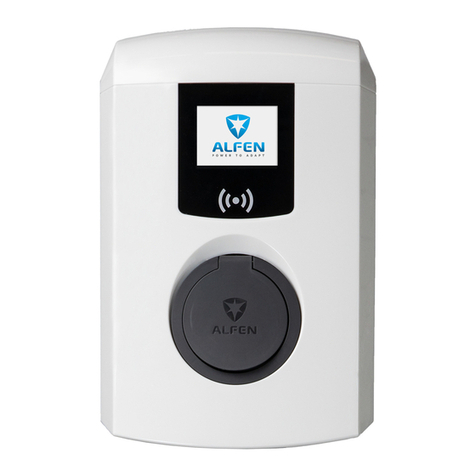
The Alfen Charge Point (the “Product”) is intended
exclusively for charging electric vehicles and, when installed
correctly, may be used by untrained individuals.
Installation, commissioning and maintenance of this
•
regarding safety and incident prevention
• Comprehensive knowledge of applicable electrical
regulations.
• The ability to identify risks and avoid potential hazards.
• Received and read these installation and operation
instructions
1.2 General safety
DANGER!
These safety instructions are important to ensure safe
operation. Failure to comply with them in accordance with
general electrical safety regulations could result in a risk of
Using this product is expressly prohibited in the following
situations:
•
substances.
• If the product is located in or close to water.
• If the product or its individual components are damaged.
• Usage by children or individuals not able to properly
assess the risks associated with using this product.
Alfen ICU B.V. (“Alfen”) shall not be liable in any way, for any
kind of damage, and all warranties on both the product and
accessories shall become void where:
• The ambient temperature is below -25°C or above 40°C.
• the Products have been subject to misuse, faulty
installation or maintenance; or
•
repaired; or
• the manuals, operation and maintenance instructions
which are applicable for (parts) of the Products or have
been provided by Alfen are not complied with; or
• the Products are used in the vicinity of explosive or
• in case of normal wear and tear; or
• there is a failure of the distribution network; or
• there is a force majeure situation, or the defect is
otherwise caused from the outside.
More extensive safety information is available in the
relevant sections of this document.
1.3 Disclaimer
version 4.4.0 or higher.
This document has been subjected to rigorous technical
review before being published. It is revised at regular
included in the subsequent issues. The content of this
document has been compiled for information purposes only.
document as precise and up-to-date as possible, Alfen shall
not assume any liability for defects and damage which
results from the use of the information contained herein.
In no event will Alfen B.V. be liable for direct, indirect,
resulting from any errors or omissions in this manual. All
obligations of Alfen are stated in the relevant contractual
agreements. Alfen reserves the right to revise this
document from time to time.
Any deviation to the Products including, but not limited
colours), hereafter referred to as ‘Customisation’, can alter
quality and/or product lifespan. Alfen is not liable for any
damage to, or caused by, the product (including applied
Customisation) if this damage is caused by this applied
Customisation. Contact your dealer for more information on
Customisation versus the default product.
1.4 Copyright
Copyright © Alfen N.V. 2019. All rights reserved. The
disclosure, duplication, distribution and editing of this
document, or utilization and communication of the content
are not permitted, unless authorized in writing. All rights,
including rights created by patent grant or registration of a
utility model or a design, are reserved.
