EOS FL 2000 K User manual

1
FL 2000 K
FL 2001 K
Druck-Nr. 29342615en /33.06
Installation and User's Guide
FL 2000 K / FL 2001 K
IP x4
GB

2
Important Notes
Improperly installed hardware can
present a fire hazard! Please read this
installation guide thoroughly. It is
especially important to consider
applicable dimensions and observe
the following instructions:
OThe colored light unit is designed for a
supply voltage of N 230 V AC via colored
light control unit.
OOnly an expert may install and connect
the colored light unit, control unit and
other electrical equipment. In this respect
it is especially important to meet the
required safety precautions by VDE 0100
v. § 49 DA/6 and VDE 0100 Part 703/
2006-2 § 4.
OThe control unit FL 45 is must be used to
control the colored light unit. Affix this
control unit in an appropriate location to
the outside wall of the cabin.
OWARNING! Never mount the unit directly
over the oven in the cabin ceiling or on
the cabin wall.
OThe unit is equipped with a safety glass
panel. Never operate the unit with a
broken safety glass panel.
OOnly a locally certified electrician
may hard-wire the sauna system
(sauna oven, control unit, lighting,
etc) to the power supply. All
connecting lines laid on the inside of the
sauna cabin must be able to withstand a
surrounding temperature of at least
140°C. Silicone lines are recommended
for practical purposes.
OWARNING: Do not cover rear side of
unit with insulating material (rock wool,
etc.) so as not to create an accumulation
of heat.
Installation
Installation inside the cabin unit
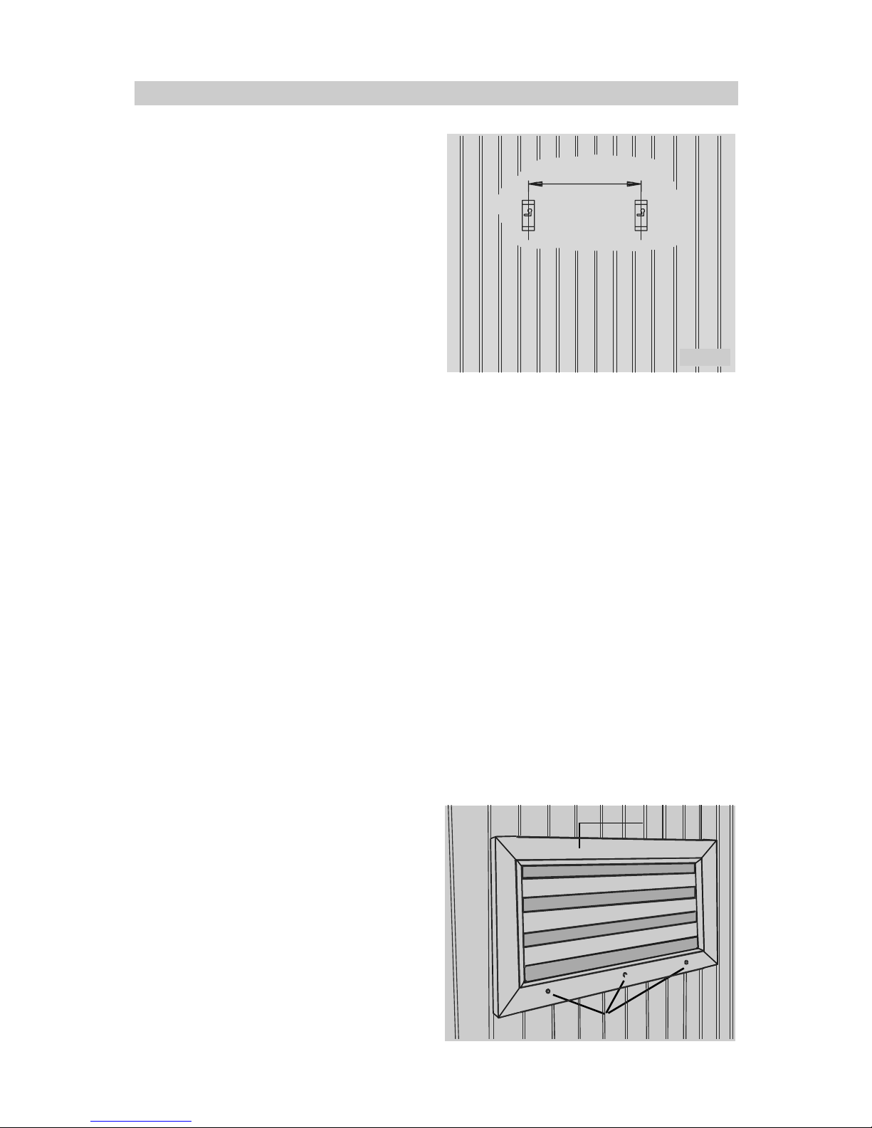
To facilitate this, it is necessary to cut a
rectangular opening of 670 x 280 mm into
the ceiling of the cabin for the small colored
light unit (FL 2000) as in Illust. 1. For the
larger colored light unit (FL 2001) you will
need an opening of 1280 x 280 mm.
The installation inside the cabin unit must
not be carried out in the area 1 of the cabin
(illustr. 2)!
In case of installation beneath the ceiling,
the colored light unit only has to be installed
in the areas 2 and 3 (illustr. 2).
Illust. 1
rectangular opening
670 x 280 mm (FL 2000)
1280 x 280 mm (FL 2001)
Illust . 2
Area 1
Area 4
Area 2
Area 3
0,5 m
0,5 m
0,3 m
power socket
Colored light unit in the ceiling
english

3
Installation
cabin ceiling
colored light unit
Illust. 6
angle bracket
wooden frame
wooden screw 4 x 25
angle bracket
cabin ceiling
colored light unit
Illust. 5
Shut the stillage afterwards and tighten the
quick release fastener screws (illust 7).
Illust. 7
Illust. 2
Release the quick release fastener screws
(illust. 2) and open the stillage.
Insert the unit bottom-up into the rectangular
opening and fix the unit at the lateral angle
brackets with each two wooden screws 4
x 25 (illustr. 3 to 6).
Illust. 3
Illust. 4
Hinge
Wooden screws
quick release
fastener screws
english

4
Installation
Now insert the unit with the mounting screws
into the holes in the mounting brackets and
snap it into place by pushing it sideways.
Fasten the unit with the two wooden strips
(Illust. 12).
Installation on the cabin wall
You may only install the unit on the cabin
wall in areas 2 and 3 inside the cabin
(Illust. 8).
Illust. 8
Area 1
Area 4
Area 2
Area 3
0,5 m
0,5 m 0,3 m
power socket
Mount the two included mounting brackets
on the wall, leaving a horizontal distance of
500 mm (for type FL 2000) or 1110 mm (for
type FL 2001) respectively between them
(Illust. 10)
angle bracket
Illust . 9
Springschrauben
stillage
Illust. 12
To accomplish this, remove the angle
brackets on each side (Illust. 9), since they
are not needed for installation on the cabin
wall.
500 mm (FL 2000)
1100 mm (FL 2001)
mounting bracket
Illust. 10
Unscrew the mounting screws on the rear
side of the unit somewhat, so as to create a
4 mm gap between housing and the screw
head (Illust. 11).
mounting screw
Illust. 11
500mm
(1110 mm)
4mm
english

5
Connect the control unit according to the
wiring diagram below.
color coding: green/yellow =PE
1=N
2 = red
3 = yellow
4 = green
5 = blue
Wiring diagram for type FL 2000 K / FL 2001 K with control unit 45 FL
feeder cable
control unit
red
yellow
green
blue
N
gr/ye
black
black
black
black
blbl
bl
wh
wh
wh
blue
green
yellow
red
S1
S2
S3
S4
br
br
br
br
wh
wh
wh
wh
4 special-purpose fluorescent lamps
4 fluorescent lamp ballasts à 20 W (40 W)
4 starters S 10 5-80 W
Start-up
Start operation of the colored light unit with
the control unit, type 45 FL. To accomplish
this, refer to the manual of the control unit.
english

6
Replacing lamps and starters
WARNING! Use only original
manufacturer´s replacement parts.
Release the quick release fastener screws
and open the stillage.
Now you can change the lamps and/or the
starters. The lamps and starters can be
removed by unscrewing them from their
sockets.
Now insert the new lamps or starters into
the sockets and turn them about 90 degrees.
Shut the stillage afterwards and tighten the
quick release fastener screws
Performance data
FL 2000 K
4 special-purpose fluorescent lights,
18 W each
voltage: 230 V AC N 50 Hz
power consumption: 80 W
FL 2001 K
4 special-purpose fluorescent lights,
36 W each
voltage: 230 V AC N 50 Hz
power consumption: 160 W
Both colored light units must be operated
with the colored light control unit 60FL, ECON
F1 or EMOTEC C55.
english

7
Effect of the colors
The emotional effects of the colors are
perceived through the eyes. From there
the color rays are relayed by a series of
complex processes to the brain and unfold
their effects in form of certain impressions
and energies.
Neural color reception leads to an activation
of the immune system. Depending on the
color, specific physical systems are
addressed and activated.
The physical absorption essentially takes
place through direct color exposure to the
skin.
The chemical absorption takes place in the
gastrointestinal tract by ingestion of various
colorful foods.
BLUE, the color of sky and water, is
associated with yearning, vastness and
cold. The cold slows down bodily functions.
This is the reason why blue is said to have
a soothing and relaxing effect and to help in
cases of nervous disorders, insomnia,
uneasiness and fearful states.
GREEN is the color of nature. Green light
soothes and inspires at the same time and
helps recuperation and regeneration. Green
light is thought to positively influence the
lungs and the respiratory system and be
helpful for nervous conditions, headaches
and joint inflammations.
YELLOW is said to promote positive
attitudes and general wellness. Yellow
colors can stimulate and strengthen nerves
as well as dissipate gloom and melancholy
and counteract stomach and intestinal
disorders as well.
RED is associated with fire and blood. It is
the color of activity, vitality and warmth. Red
is said to stimulate blood flow and thus
increase well-being and vitality.
english

8
Guarantee
Guarantee
The guarantee is taken over according to the
legal regulations at present.
Manufacturer’s warrenty
- The period of warrenty starts from the
date of purchase and lasts up to 2years
for commercial use and 3 years for pri-
vate use.
- Always include the completed warrenty
certificate when returning equipment.
- The warrenty expires for appliances
which have been modified without
manufacturer’s explicit agreement.
- Damages caused by incorrect operation
or handling through non-authorized
persons are not covered under the terms
of warranty.
- In the event of a claim, please indicate the
serial number as well as the article code
number and type name with expressive
description of the fault.
- This warrenty covers damaged parts but
no defects due to wear and tear.
In case of complaint please return the
equipment in its original packaging or other
suitable packaging (caution: danger of
transport damage) to our service department.
Always include the completed warrenty
certificate when returning equipment.
Possible shipping costs arising from the
transport to and from point of repair cannot
be borne by us.
Outside of Germany please contact your
specialist dealer in case of warranty claims.
Direct warranty processing with our service
department is in this case not possible.
Equipment start-up date:
Stamp and signature of the authorized
electrician: Service address:
EOS-WERKE Günther GmbH
Adofl-Weiß-Straße 43
35759 Driedorf, Germany
Tel. +49 (0)2775 82-0
Fax +49 (0)2775 82-431
www.eos-werke.de
english
This manual suits for next models
1
Table of contents
Popular Medical Equipment manuals by other brands

Spencer
Spencer spn01 user guide

Medifa
Medifa 800200 Service manual

Alpha Communications
Alpha Communications TekTone Tek-ENTRY Operation, installation and service manual

BHM Medical
BHM Medical MINISTAND 865 Series Technical manual

Storz
Storz ARTip CRUISE UR500B Instructions for use

Schiller
Schiller MAGLIFE LIGHT user manual

CME America
CME America BodyGuard 323 Clinician Quick Reference

Spencer
Spencer Davis Instructions for use

EKF Diagnostics
EKF Diagnostics Stanbio HemoPoint H2 user manual

ResMed
ResMed Ultra Mirage Clinicians Guide

Ambu
Ambu aView 2 Advance quick start guide

Abiomed
Abiomed Impella RP Instructions for use & clinical reference manual