7
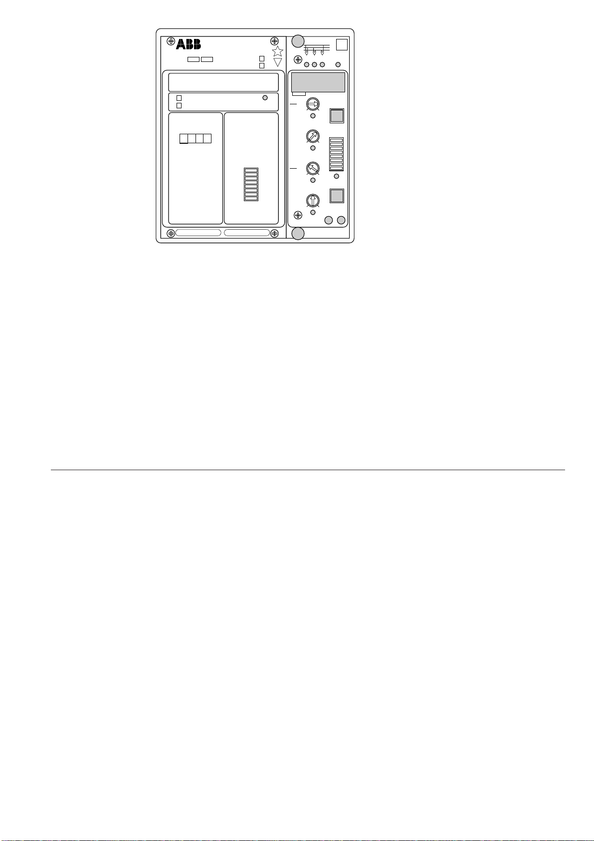
2. The yellow LED indicators (U12, U23 and
U31) on the upper black part of the front plate
indicate, when lit, that the corresponding
voltage value is currently being displayed.
3. The red IRF indicator of the self-supervision
system indicates, when lit, that a permanent
internal relay fault has been detected. The
fault code appearing on the display once a
fault has been detected should be recorded
and notified when service is ordered.
4. The green Uaux LED on the front panel is lit
whenthepower supplymoduleoperates prop-
erly.
5. The LED indicator below a particular setting
knob indicates, when lit, that the setting
value of the knob is currently being dis-
played.
6. The LED of the SG1 switchgroup indicates,
when lit, that the checksum of the switch-
group is currently being displayed.
The start and operation indicators, the function
of the SG2 software switchgroup and the func-
tions of the LED indicators during setting are
described more detailed in the user's manual
"Combined overvoltage and undervoltage relay
module SPCU 3C14".
Start and
operation
indicators 12
IRF
>
U
23
U
31
U
U
1315
[ ]
s
k>
t
0.5
0.05 1.0
0.8
0.4
5.0
1.0 12
0.8
1.2
1.6
STEP
RESET
SG1
01
1
2
3
4
5
6
7
8
<
U
n
U
>
U
<
t
[ ]
s
>
U
<
U
SPCU 3C14
n
U
<
U
1.2
STEP
RS 422 Ser.No.
SPAU 130 C
2
5
1308
f
n= 50Hz
60Hz
1
2
3
4
5
6
7
8/
>
tt
n
)(
>
n
)(
<
<
/
tt
%
[]
%
[]
U
aux
80...265V ~
–
18...80V –
SPCU 3C14
REGISTERS
0000
1
2
3
4
5
6
7
8
01
SGR
n
/
UU
U
U
n
U
=100V 110V
>
n
/
UU
max
n
/
UU
<
n
/
UU
min
1. The relay module is provided with two opera-
tion indicator located in the right bottom
corner of the front plate of the relay module.
One indicates operation of the overvoltage
stage and the other operation of the under-
voltage stage. Yellow light indicates that the
concerned stage has started and red light that
the stage has operated (tripped).
With the SG2 software switchgroup the start
and trip indicators can be given a latching
function, which means that the LEDs remain
lit, although the signal that caused operation
returns to normal. The indicators are reset
with the RESET push-button. An unreset
indicator does not affect the operation of the
relay.
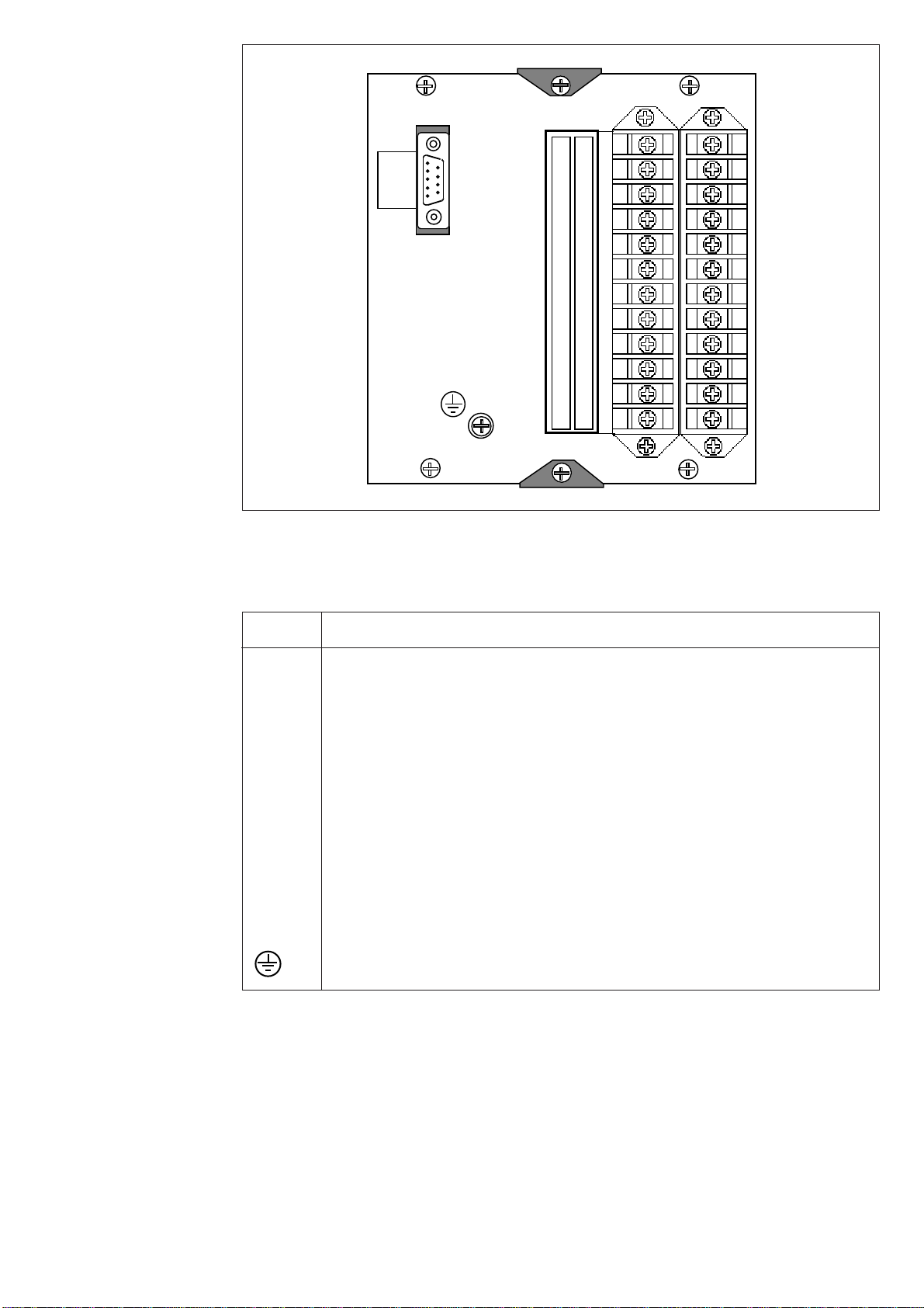
Combined power
supply and I/O
module
The combined power supply and I/O module
(U2) is located behind the system front panel of
the protection relay and can be withdrawn after
removal of the system front panel. The power
supply and I/O module incorporates a power
unit, four output relays, the control circuits of
the output relays and the electronic circuitry of
the external control input.
The power unit is transformer connected, that
is, the primary side and the secondary circuits
are galvanically isolated. The primary side is
protected by a slow 1 A fuse F1, placed on the
PC board of the module. When the power
source operates properly, the green Uaux LED
on the front panel is lit.
The power supply and I/O module is available
in two versions which have different input volt-
age ranges:
- type SPTU 240S1 Uaux = 80...265 V ac/dc
- type SPTU 48S1 Uaux = 18...80 V dc
The voltage range of the power supply and I/O
module inserted in the relay is marked on the
system front panel of the relay.