Eowave Eobody2HF Wireless User manual

Eobody2HF Wireless
USB Wireless Sensor Interface
The wireless solution for dancers and installations
User’s Manual

Before using your Eobody2 HF, make sure you have read the following instructions carefully.
Do not open or modify the unit or its main adapter when the unit is externally powered.
During ligthning, unplug the unit, make sure the main adapter (if one) is not plugged.
Before cleaning your Eobody2 HF, make sure the main adapter and/or any external elements are
disconnected from the unit.
Do not try to repair the interface or the components inside of it. Please contact eowave for technical support
Do not use your Eobody2 HF nor store it in dusty areas, damp areas, extreme temperatures, exposed to
direct sunlight, areas prone to strong vibrations.
Do not insert any objects nor pour any liquid into the unit.
Protect the unit against violent shocks.
Never touch your Eobody2 HF nor its adapter with wet hands when it is plugged in.
Never place heavy objects on your Eobody2 HF.
All trademarks are property of their owners.
Safety instructions
Eobody2HF / Safety instructions 2

Congratulations
Congratulations!
You now own a new Eobody2 HF, a versatile wireless usb-to-sensor interface.
Eobody2 HF is unique because it offers an internal powerful processing to shape the outcoming sensor signal and
let you get the best results in an intuitive and easy way. No MIDI interface needed, no skills in computer program-
ming required. The freedom of wireless.
Unpacking
Your Eobody2 HF case should include the following items. Make sure everything is in the box.
- 1 Eobody2 HF Wireless receiver
- 1 Eobody2 HF Wireless transmitter
- 1 usb mini cable
- 1 rechargeable battery (inside the transmitter)
in option:
dance pouch
additionnal arm band
belt
Naming things
Eobody2 HF Wireless receiver: this part is connected to the computer via USB. The receiver receives the
data from the transmitter unit.
Eobody2 Wireless transmitter: sensors are connected to the transmitter. The transmitter (in a box or in a
soft pouch) can be carried by dancers for dance peformances or integrated into an instrument or any other
object.
Eobody2HF / Congratulations / Unpacking 3

From the Idea…
Men have always dreamt of new ways of communication. Through ages, men have thought of their body as a tool of com-
munication. And indeed, when communicating, this is not only your voice, nor the only expression in your face that trans-
mits a message, but your entire way of being. This is your entire body which projects you inside the individual world of one
another. In all cultures, men have developped new ways of communication through dance, music, art. And still in a matter
of a better communication, men have always worked to improve the interaction between men and machines, thus since
the very beginning of mechanics and later, electronics. More and more, the body has become the cornerstone of interac-
tive systems of communication. New technologies widen the range of controls. And controls have entered everyday’s life
without us noticing. Remote controls are everywhere: we control TV, we control VCRs, DVDs, stereos, ovens, climates,
windows, garage doors… Control surfaces are everywhere. Faced to art, control appears to be the new way of expression
of this early millenium. Many artists are looking for new ways of expression, of conceptualizing ideas… In this perspective,
sensors open new dimensions of expression. Eobody2 is the key link between the world of analogue sensors and digital
systems.
…To the Realization
An early version of Eobody2 has been rst presented at NIME 2007 (New Interfaces for Musical Expression) hold at New-
York University in June 2007. The idea was to keep a plug and play modular system to use sensors as well as relays,
CVs... The usb 8 SensorBox is one of the rst modules of this new Eobody2 interactive system. One SensorBox enables
to plug 8 sensors and use them directly with your sequencer software, but you can also plug more if you need more inputs
for other sensors. The goal was to come to a plug & play solution and versatile solution (and at a reasonnable price) for
all those who don’t want to go into computer programming or wire soldering, but whose job is to create music, live, video
apps, sensor-based instruments or installations...
4

Table Of Contents
Safety instructions 2
Congratulations / Unpacking 3
I. Register and Install
Download and install the editor / Download the manual 6
II Quick Overview: What’s what 7
III. Quick Start 8
Connect the receiver to your computer / Connect a sensor to the transmitter / Check connection
IV. Communication Channel Selection 9
Changing the transmitter & receiver communcation channel
V. Questions of Power 10
Receiver powering / Transmitter Powering
VI. Understanding the receiver LED language 10
VII. Eobody2 editor 11
Open the editor
Eobody2 and your computer 12
Select Eobody2 MIDI port /dumpall/active inputs/savemen/initall/rereadmen
Internal process & editor parameters 13
Analogue Inputs Parameters window 14
Inverse/ status/digital zoom and offset / lter / gate/ message channel
Formating messages to host 17
Type / CC Control Change / Program Change message PC / Pitch Bend PB /
Conguration map for analogue inputs 19
VIII. Sensors compatibility 19
IX. List of MIDI Controllers 20
X. MIDI Implementation 21
XI. Technical specications 22
Contact and support 23
Eobody2HF / Table Of Contents 5

I. Register and Install
Register
You may register on www.eowave.com/register.php by entering your Eobody2HF serial number. This number
is located on a sticker on the back of the receiver unit. Registering will give you a member access to the down-
load page to download the editor, user manual, patches, news, upgrades...
On www.eowave.com/register.php, ll in the online registration card and enter your serial number.
Downloads & online documentation
Download and install the editor
On www.eowave.com/download.php page, click on eobody2HF_editor.
Eobody2 HF Editor is Mac and PC compatible.
Eobody2 HF editor needs Max runtime as a driver. If you don’t already have a Cycling74 Max5 version
installed on your computer, you may download a 30 days free trial of Max5 on www.cycling74.com
This free trial will automatically install Max runtime on your computer. When the 30 days trial is over, Max5
runtime will remain on your computer.
When you have succefully installed Max5 runtime, you may open Eobody2 HF editor.
For any questions or support concerning the installation of the editor, contact [email protected]
For Maxers
If you are a Maxer and want to use Eobody2HF with Max/MSP/Jitter, note that the Eobody2 HF Editor is a
Max5 collective le. This avoids having 2 Max apps running on the same computer.
When the installation of the editor is done, a window pops up and tells you that the installation was successful.
Download the manual
On www.eowave.com/download.php page, click on the Eobody2 HF manual pdf le. This manual is also avail-
able in French.
Download the tutorials
Different tutorials are also available on www.eowave.com/download.php page.
Eobody2HF / Register and Install 6

II. Quick Overview: What’s What
Eobody2HF Receiver
The receiver is connected to your computer via USB. It receives the
sensor datae sent by the transmitter.
receiver tri-color LED
USB I/O
Eobody2HF Transmitter
Sensors are connected to the transmitter. The sensors are plugged to the 3 pins connectors.
Eobody2HF / Quick Overview: What’s What
sensor 3 pins connector
inputs 1 to 16
activity LED on/off Battery charge via USB I/O
USB I/O for editing settings
via the editor
7

Eobody2HF / Quick Start
III. Quick start
Connect the receiver to your computer
Connect the receiver to your computer with the USB mini cable (or to any USB hub connected to your computer).
You do not need any MIDI interface. Your Eobody2 HF will be recognized as a new audio device for PC, as
Eobody2 MIDI interface with Mac. When right connected, the receiver LED turns green.
Two or more Eobody2 HF can be connected directly to the USB inputs of your computer, but they can also be connected
via a USB hub. When more than one Eobody2 HF are connected, they will appear like different audio peripherical with
PCs, different Eobody2 HF MIDI interface with Mac. In this case, you will be able to rename your Eobody2 with different
names. When the units have been named, their given name will appear. (See Global Parameters Section). Theorically, 16
receivers may be active in the same area, but this number may be reduced depending on the area radio perturbation...
Connect a sensor to the transmitter
Eowave sensors compatible with the Eobody2HF wireless interface have a thin 3 pins connector. To connect a sensor to
the transmitter, just plug the 3 pins connector in one of the male 3 pins connector from the transmitter. Sensors like ac-
celerometers need 2 inputs. (See sensor technical datasheets).
Check transmission
Try a sensor. When acting a sensor, the receiver LED blinks red. It means that the receiver is receiving the datae.
On Windows (here the French version on XP),
your eobody2 should appear as an audio device
in the audio /video & game device window.
On OSX it's even easier, eobody2 should
appear in the audio & midi configuration
panel.
Respect the sensor polarity
Note that this is highly recommanded to connect the sensors to the transmitter
before starting your sequencer software. Unplugging sensors while using your
sequencer software may cause breaks during the usb data transmission which
could lead you to restart your software.
8

IV. Communication Channel Selection
Per default, communication channel is set on channel #1.
This is an operation you’ll have to do the rst time you use your Eobody2 HF system if you want to set your system on
another communication channel than channel #1 set per default. Once set on a particular channel, your emitter/receiver
system will communicate on the same channel. There are 12 communication channels available. If you want to use your
system on channel #1, you do not have to change the communication channel.
Changing the transmitter communication channel
(this is only necessary when more than one unit is used in the same area)
Plug the transmitter via USB to your computer. Switch the transmitter on. The transmitter LED must light when it’s on.
Once you have launch Max5 runtime, open the Eobody2HF editor. In the editor, select the MIDI interface you are using in
the list (Eobody2HF).
Click on RC Channel to set the new transmission channel. The following window opens:
Follow the instructions:
1. Enter command mode by clicking on commandmode 1
2. Initialize command mode by clicking on INITCOM. You get the message AT OK -- if not, try again.
3. Display active channel by clicking on ATCH. You get the message AT +new channel
4. Set new channel from the scrolling menu. You get the message AT OK
5. Save setting by clicking on ATWR. You get the message AT OK
6. Exit command mode by clicking on commandmode 0
Changing the receiver communication channel
You will proceed the same way with the receiver.
Plug the receiver to the usb in of your computer. The receiver LED will turn green when right plugged.
Make sure to select the same tranmission channel than the one set on the transmitter.
9
Eobody2HF / Communication Channel Selection

Receiver powering
USB enables self powering. Just plug the usb from Eobody2HF receiver to your computer usb in. The receiver LED will
turn green and off when the unit is well connected.
Transmitter powering
One of wireless systems biggest issue is the question of the transmitter autonomy vs battery weight.
The transmitter is delivrered with a rechargeable lithium battery. The battery autonomy depends on the number of sensors
used and on the type of sensors used.
To recharge the battery, plug the transmitter via USB to the USB I/O of your computer. At the rst use, we recommend
that you charge the battery for 1 night.
Eobody2HF / Power
V. Questions of power...
VI. Understanding the Receiver LED language
The receiver LED is a tri-color LED. Here is the color code:
1 It’s green!
When connected to the USB in of your computer, the receiver LED will turn green. This means that it’s well
connected and active.
2. It’s green/orange!
When the receiver LED blinks green/orange, it means that the transmitter communicates with the receiver and
sends datae, and/or vice versa.
3 It’s red!
A red LED means that the receiver is in programmation mode.
4 It’s red/green
Check channel
10

Eobody2HF / Eobody2 editor
VII. Eobody2HF editor
The Eobody2HF editor enables to edit the emitter settings and save them into the emitter internal memory. Note
that the emitter will be the core of your settings, not the receiver. The emitter must be
plugged before starting the editor.
Open the editor
One of the rst thing you did when you got your Eobody2HF was to download and install the editor. Refer to “Register
and Install section if you have not). Once Max5 runtime is launched, double click on the editor icon to open it. The
following window opens:
11
Eobody2HF / Eobody2HF editor
Eobody2HF and your computer
Factory settings
Factory settings are controllers 1 to 16 on MIDI channel 1.
1. Select Eobody2 MIDI port
Eobody2 uses the MIDI protocol to transfer data, that means it is com-
patible with almost every MIDI software.
First, you need to select “eobody 2” in the midi port scrolling menu.
The factice LEDs in & out will light up when receiving/sending mes-
sages.
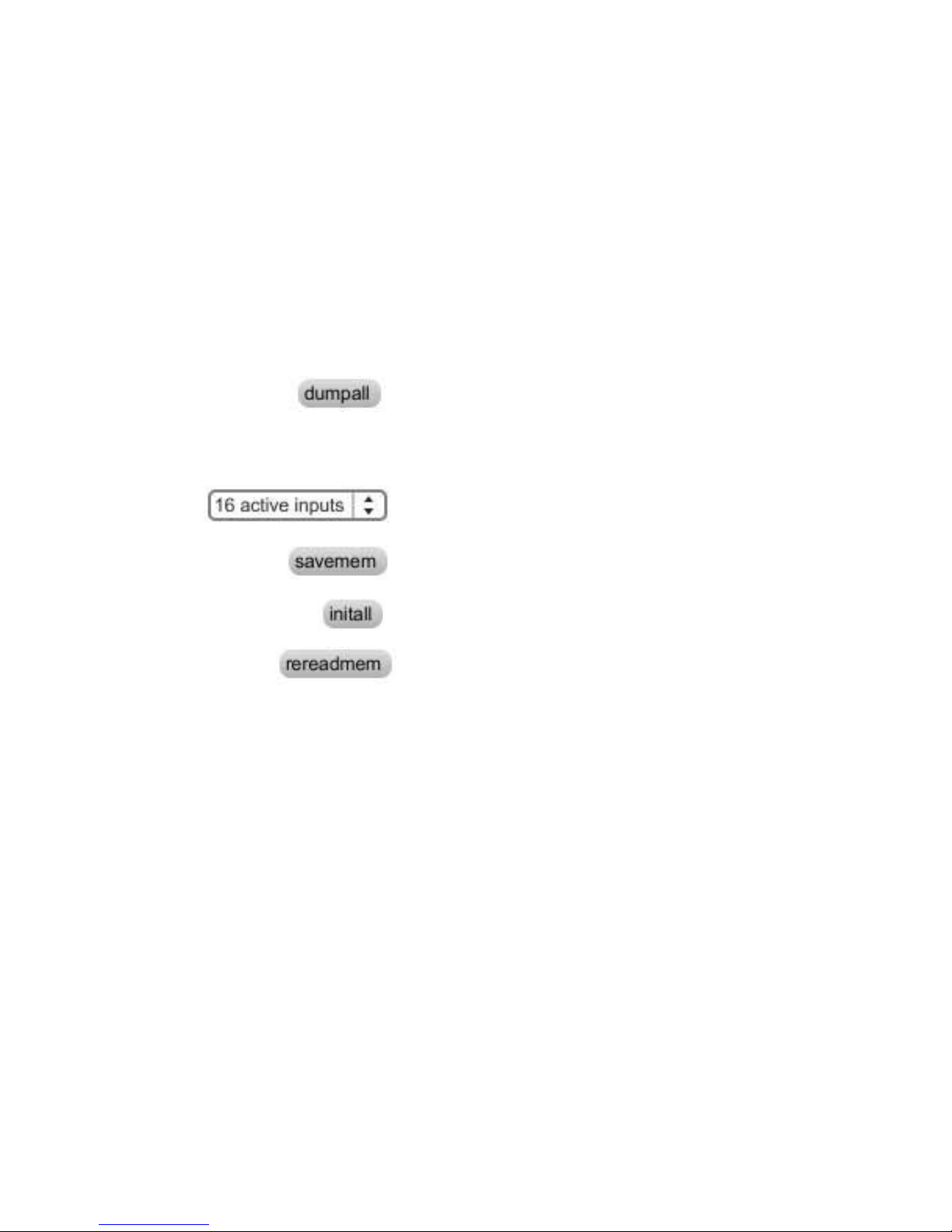
2. Dump all current parameters from Eobdy2HF memory to your com-
puter by clicking on “dumpall”
3. Adjust the analogue inputs parameters settings you need. Refer to
the following section for a detailled description of each feature.
4. Set the number of active inputs to avoid unwanted messages and to
increase the response speed.
5. Click on “savemem” to save parameters into the Eobody2HF inter-
nal memory.
6. “Initall” will restore factory settings when conrmed by a click on
savemem.
7. Rereadmem will reload last saved memory
12

Eobody2HF/ Internal process & editor parameters
Internal process & editor parameters
Multiplexer 12 bit A/D
converter
PGA
Programmable
Gain
Ampli er
analogue inputs
signal processing message out
parameters
non-volatile memory
to con guration i/o
Eobody2 offers a complex internal pre-processing of the data you may set in the editor.
Eobody2 internal processing
sensor in
message formating
& bit reduction
PGA
analogue zoom
digital zoom
state on/off
0
127
-127
offset low-pass filter
(32 bits processing)
lag
noise filtering
gate
analogue domain
(0-5V)
digital domain (16 bits ) to host
up to 32x amplifier
12 bits
AD converter
inverse
note on
note off
hi
low
note detection
parameters action on the signal path
analogue domain (0-5V)
digital domain (16 bits)
Signal path and Eobody2 editor ne parameters internal processing
13

The parameters window enables to adjust internal processing parameters for each input (1 to 16).
Refer to the description of each parameter for use. To increase or decrease parameter values, click on the case you want
to edit and slightly move up or down your mouse. To save a conguration, click on «savemem».
What are these internal processing parameters?
Eobody2HF is not just an analogue-to-digital wireless converter, it has a unique internal processing especially designed to
analyse, process and congure the signal before it is sent to the host. This internal processing offers several advantages.
> Pre-congured parameters processings have been designed considering most common sensor use and are perfectly
adapted to sensor use for musical or video applications.
> You can use Eobody2HF directly with your software sequencer without programming needs.
> Internal processing does not use your computer cpu, so you can keep more cpu resources for your apps.
> Internal conguration can be saved inside Eobody2HF internal memory for future use.
> Parameters lter the signal to optimize data to be sent to the computer and get a better response from sensors. With
these, you will be able to choose parts of the signal to be processed, dene the signal resolution, add a noise gate, a lag
low-pass lter, inverse the signal, choose the type of message to be sent...
Eobody2HF / Parameters window
Analogue input parameters window
14
inverse
127 becomes 0 and 0 becomes 127. This way you may inverse the curse of a sensor. With an
expression pedal, for example, you’ll be able to inverse its curse.
status
on/off
The status eld indicates whether the signal on an analogue input should be converted into a digi-
tal message or not. This eld may be set to ON or OFF. If the eld is set to OFF, the input is said to
be inactive and no message relating to that input will be generated, even if a signal does physically
enter the device. If the eld is switched back to ON, the input is active and its associated message
will be sent each time the signal connected to that input varies in level.
Note:The smaller the number of active inputs is, the less data will be transmitted avoiding proces-
sor computation.
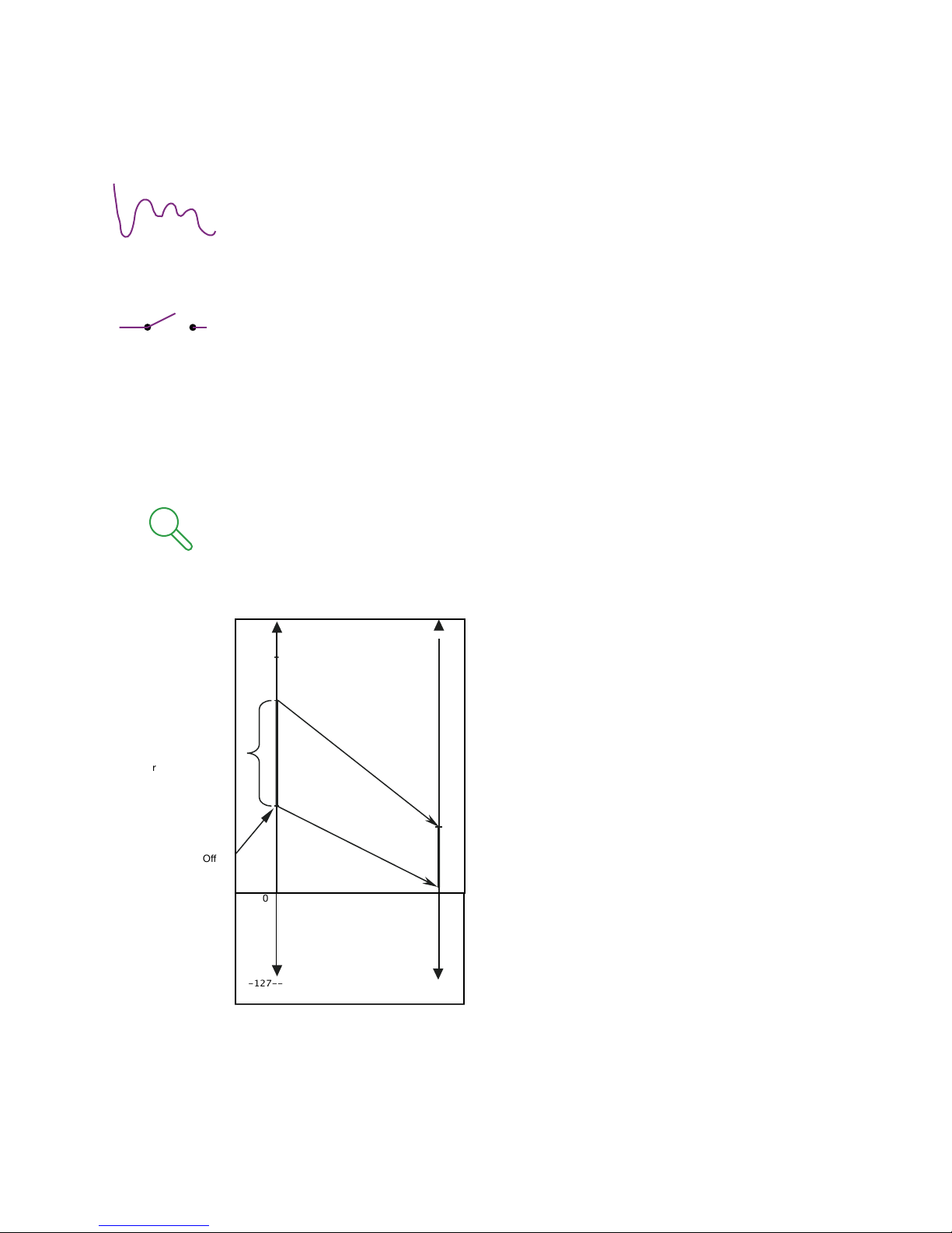
zoom and offset
zoom: max/mid/low/off on 7
offset: -127 to +127
Eobody2HF / parameters
0
127
127
Digital value
(12 bits)
MIDI data
(7 bits)
MIDI conversion
zoom setting
=
real sensor range
Offset
-127--
Want to stay in the 7-bit MIDI world...
Those two parameters (digital zoom and offset)
specify how the real range of an analogue input can
be mapped on a 7-bit MIDI value. As a matter of fact,
a sensor does not necessarily have a range equal
to the reference voltage of the Analogue to Digital
Converter. A custom scaled zoom has been imple-
mented on the digital value to take advantage of
the 12-bit resolution of the A/D converter. Then, the
user can select the sensor’s range within the 12 bits
dynamic by specifying a window size and an offset.
The selected range can then be converted into 7 bits
MIDI data without greatly increasing the quantication
step, as shown in the illustration.
The digital zoom & offset parameters may be very
useful to modulate a lter on a certain part of the
amplitude.
15

Eobody2HF / Parameters
gate
noise gate:8 values [0-7]
lter
0-64
32 bits low-pass lter that smoothes the signal - for unstable sensors.
message Channel: [1-16]
This eld enables the user to select a MIDI channel to which the MIDI message will apply (1 to 16).
Sensor Noise band
Sensor signal
Sampled value
Sampled value
+MIDI message
2* (noise)
0t
A noise gate threshold reduces
the bit depht of the signal. If the
analogue signal moves inside the
range of the noise gate, no mes-
sage will be sent. This eld enables
the user to set the width of the
range. A large range will be very ef-
fective against strong noise but will
make the values less sensitive to
a relevant change of the analogue
signal. A threshold of 5 corresponds
to 127 different possible values (ie:
the analogue has to change at least
of 32 (from 4095 above or under its
current position to be detected as
changing). A threshold of 7 corresponds to 5 bits, usefull for switches or all on/off sensors.
16

Eobody2HF / Parameters
Formating messages to host
type
This is one of the most important conguration parameters, since it determines which type of MIDI message the device is
going to send in response to variations in a particular analogue input.
Eobody2 is capable of generating 5 different messages:
• CC: Control number change (Control change) 7 bits
CC: Control number change (Control change) 12 bits (the 5 LSB bits are mapped on CC number + 64
• Note: Note on Trigger
• PC: Program change
• PB: Pitch bend (Variation in pitch) real 12 bits
• PB: Pitch bend (Variation in pitch) mapped 14 bits
• ATm: Monophonic aftertouch (Channel pressure)
CC Control Change
This is the type of message which will likely be most often used for controlling sound parameters. The value of the ana-
logue signal acts directly upon the value of a MIDI controller, using a MIDI controller Value Change message (control
change). The number of the controller can be set by the user. If 12 bits resolution is selected, this message will actually
send two Control Change messages.
The controller specied in the val eld will send the 7 least signicant bits whilst the controller specied in the “low” eld
will send the 3 most signicant bits, on the same MIDI channel.
Note on message
N-ON trigger / hi-low
The analogue signal must correspond to an envelope changing with time and which has a maximum value. 3 parameters
need to be specied: note sent, higher threshold, lower threshold. Eobody2 analyses this envelope: once the envelope
has reached the higher threshold, a MIDI note on message (NOTE ON) is generated. The velocity associated with the
note is xed to 127. The note number contained within the message is adjustable by the user. As long as the envelope
stays above a threshold point, named NOTE OFF threshold, the note is maintained (no new MIDI message is sent). When
the level falls beneath the NOTE OFF threshold point, a MIDI NOTE OFF message is sent to turn the note off. To sustain
the note for a long period of time, the NOTE OFF threshold point must be set on a small value. Conversely, to make the
note stop shortly after the peak has been detected, the NOTE OFF value must be higher. This type of message is useful
in using sensors to generate MIDI notes.
low 0 - 127
This eld enables the user to congure the note on activation level for trigger messages or for the MSB controller number
with a lower threshold.
hi 0 - 127
This eld enables the user to congure the note on activation level for trigger messages or for the MSB controller number
with a higher threshold.
17

Signal
t
NOTE ON message
NOTE OFF message
NOTE ON
threshold
NOTE OFF
threshold
tNOTE ON tNOTE OFF
Program Change message PC
The analogue signal must correspond to an envelope changing with time and which has a maximum value. You will have
to specify 3 parameters, Program Change sent, higher treshhold, lower treshold. Eobody2 analyses this envelope: once
the envelope has reached the higher threshold, a MIDI Program Change message is generated. The Program Change
contained within the message is adjustable by the user. As long as the envelope stays above a threshold, named lower
threshold, the Program Change is maintained (no new MIDI message is sent). When the level falls beneath the lower
threshold, the Eobody2 is ready to receive a new Program Change message.
Pitch Bend PB
This message allows an analogue signal to generate a MIDI message of the pitch change type (pitch bend). Pitch is usu-
ally coded over 14 bits. If the 7 bits resolution is chosen, they will be mapped on the 7 most signicant bits of pitch infor-
mation controlled by the analogue signal. However, since Eobody2 does 12 bits conversions internally, the whole 12 bits
can be mapped to take better advantage of the pitch bend message. This message is used to simulate the pitch changing
wheels available on most MIDI keyboards.
Monophonic Aftertouch ATm
This message allows an analogue signal to generate a channel pressure type MIDI message (channel aftertouch). This
pressure message affects a whole MIDI channel, regardless of what note is played. The channel number to which the
pressure information is applied is selected by the user.
value val: 0 - 127
This eld enables the user to set the xed parameter of a MIDI message associated with an analogue input. This param-
eter value may correspond to a MIDI note number, a MIDI controller number or a MIDI program number, depending on the
type of MIDI message which is chosen.
Eobody2HF / Formating to host 18

Conguration map for analogue inputs
Eobody2HF / Conguration map for analogue inputs
Type of message Res. Value Hi Low
CC - Control Change 7 bits CC value
CC - Control Change 12 bits CC value
Note - Note on trigger 7 bits note number higher threshold lower threshold
PC - Program Change 7 bits PG value higher threshold lower threshold
PB - Pitch Bend 12 bits
PB - Pitch Bend 14 bits
ATm - monophonic aftertouch 7 bits
19
VIII. Sensors compatibility
Sensor compatibility
Eowave sensors designed for Eobody2HF have been developped to get the best results from the sensor.
Eowave does not warrantee the use of sensors from other brands or “handmade”.
Sensor connections compatibility
If you already have some Eowave sensors with jack 6,35’’connectors, you may build an adapter jack 6,35’’ to 3
pins. You can also purchase one from Eowave.
Sensors compatibility with 3,3V
Note that some active sensors requiring more than 3,3V, such as infrared sensors, cannot be used with the
Eobody2HF. Check the power consumption of the sensors before using them.

Eobody2HF / List of MIDI controllers
IX. List of MIDI Controllers
N° Function Value
0 Bank Select 0-127 MSB
1 Modulation wheel 0-127 MSB
2 Breath control 0-127 MSB
3 Undefined 0-127 MSB
4 Foot controller 0-127 MSB
5 Portamento time 0-127 MSB
6 Data Entry 0-127 MSB
7 Channel Volume 0-127 MSB
(formerly Main Volume)
8 Balance 0-127 MSB
9 Undefined 0-127 MSB
10 Pan 0-127 MSB
11 Expression Controller 0-127 MSB
12 Effect control 0-127 MSB
13 Effect control 0-127 MSB
14 Undefined 0-127 MSB
15 Undefined 0-127 MSB
16-19 General Purpose 0-127 MSB
Controler
20-31 Undefined 0-127 MSB
32 Bank Select 0-127 LSB
33 Modulation 0-127 LSB
34 Breath control 0-127 LSB
35 Undefined 0-127 LSB
36 Foot controller 0-127 LSB
37 Portamento time 0-127 LSB
38 Data entry 0-127 LSB
39 Channel Volume 0-127 LSB
(formerly Main Volume)
40 Balance 0-127 LSB
41 Undefined 0-127 LSB
42 Pan 0-127 LSB
43 Expression Controller 0-127 LSB
44 Effect control 1 0-127 LSB
45 Effect control 2 0-127 LSB
46 Undefined 0-127 LSB
47 Undefined 0-127 LSB
48-51 General Purpose 0-127 LSB
Controller (1-4)
52-63 Undefined 0-127 LSB
64 Damper pedal ≤63=off ≥64=on
on/off (Sustain)
N° Function Value
65 Portamento on/off ≤63=off ≥64=on
66 Sustenuto on/off ≤63=off ≥64=on
67 Soft pedal on/off ≤63=off ≥64=on
68 Legato footswitch ≤63=off ≥64=on
69 Hold 2 ≤63=off ≥64=on
70 Sound Controller 1 0-127 LSB
(Sound Variation)
71 Sound Controller 2 0-127 LSB
(Timbre)
72 Sound Controller 3 0-127 LSB
(Release Time)
73 Sound Controller 4 0-127 LSB
(Attack Time)
74 Sound Controller 5 0-127 LSB
(Brightness)
75 Sound Controller 6 0-127 LSB
76 Sound Controller 7 0-127 LSB
77 Sound Controller 8 0-127 LSB
78 Sound Controller 9 0-127 LSB
79 Sound Controller 10 0-127 LSB
80-83 General Purpose 0-127 LSB
Controller (5-8)
84 Portamento Control 0-127 Source
Note
85-90 Undefined 0-127 LSB
91 Effect 1 Depth 0-127 LSB
92 Effect 2 Depth 0-127 LSB
93 Effect 3 Depth 0-127 LSB
94 Effect 4 Depth 0-127 LSB
95 Effect 5 Depth 0-127 LSB
96 Data entry +1 N/A
97 Data entry -1 N/A
98 Non registered 0-127 LSB
Parameter Number LSB
99 Non registered 0-127 LSB
Parameter Number MSB
100 Registered 0-127 LSB
Parameter Number LSB
101 Registered 0-127 LSB
Parameter Number MSB
102-119 Undefined
120-127 Mode messages
20
Table of contents
Other Eowave Recording Equipment manuals


