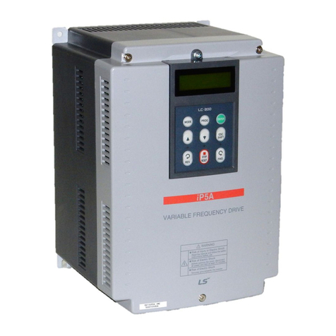
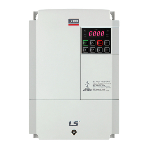
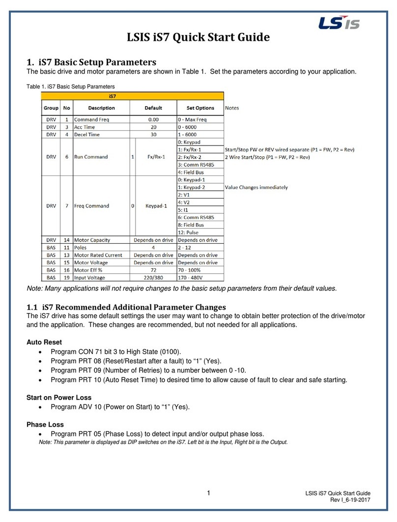
LSIS H100 Programming manual

5.5~18.5kW(200V), 5.5~90kW(400V)
AC Variable Speed Drive
H100 Troubleshooting Manual
Safety Instructions
Read this manual carefullybefore servicing or inspecting this equipment.
Keepthis manual within easy reach for quick reference.

1
Quick Reference Table
The following table listed situations frequently encountered while working with inverters. Refer to
the typical situations to quickly and easily locate solutions to your questions.
Situation
Reference
The motor is too noisy.
P. 33
I want to review recent fault trip and warning histories.
P. 18
The motor is producing too much heat.
P. 31
The cooling fan is not working.
P. 34
I want to know how I can keep the inverter when I am not using it.
P. 44
I want to initialize all parameters.
P. 16
I want to terminate the inverter.
P. 44
I want to review the input/output module.
P. 38
I want to change the fan when it exceeded the replacement period.
P. 42
I want to change the carrier frequency.
P. 14
I cannot set the parameters.
P. 30
The motor is not working.
P. 30
The motor stops when it is connected to the load or accelerated.
P. 32

2
Contents
INTRODUCTION 3
Manual Composition 3
PRODUCT IDENTIFICATION 4
ASSOCIATION MANUAL 4
SAFETY INFORMATION 5
REVISION RECORD 7
1BASIC CHECKLIST 8
Before you think it failed 81.1 Basic Operations 101.2 Parameter Change 141.3
Carrier Frequency Change 141.3.1
InitializingAll Parameters 161.3.2
Read andWrite Parameters 171.3.3
Fault Trip Monitoring 181.4
2TROUBLESHOOTING 21
Trips and Warning 212.1
Failure/Warning List 212.1.1
Troubleshooting Fault Trips 252.1.2
Troubleshooting Other Fault 30
2.2
3MAINTENANCE 35
Regular Inspection List 353.1
DailyInspections 353.1.1
Annual Inspections 363.1.2
Bi-Annual Inspections 373.1.3
Check Input/Output Module 383.1.4
Replace Cooling FAN 423.1.5
Storage and Disposal 443.2
Storage 443.2.1
Disposal 443.2.2

3
Introduction
Manual Composition
1.1 Before you think it failed
1.2 Basic Operations
1.3 Parameter Change
1.3.1 Carrier FrequencyChange
1.3.2 InitializingAll Parameters
1.3.3 Read andWriteParameters
1.4 Fault Trip Monitoring
2.1 Trips and Warning
2.1.1 Failure/Warning List
2.1.2 Troubleshooting Fault Trips
2.2 Troubleshooting Other Fault
3.1 Regular Inspection List
3.1.1 Daily Inspections
3.1.2Annual Inspections
3.1.3 Bi-Annual Inspections
3.1.4 Check Input/Output Module
3.1.5 Replace Cooling FAN
3.2 Storage and Disposal
3.2.1 Storage
3.2.2 Disposal
This section explains troubleshooting
fault trips and other common faults.
If problems are not solved, please
contact your vendor or LSIS.
This section provides information
on how to maintain the inverters on
a regular basis for different time
periods.
When there is a problem in the
inverter, please check the
input/output module. This is the
basic method to check the
hardware.
This section covers check points
when there is a problem in the
inverter.
Then check the parameter settings
using basic operations and the trip
records.
2 Troubleshooting
1 Basic Checklist
3 Maintenance

4
Product Identification
Note
The H100 75/90 kW, 400 V inverters satisfythe EMC standard EN61800-3 without installation of optional EMC
filters.
Association Manual
H100 user manual can be downloaded through LSIS homepage.
Link : http://www.lsis.com/support/download/

5
Safety Information
Read and follow all safety instructions in this manual precisely to avoid unsafe operating conditions,
property damage, personal injury, or death.
Safety symbols in this manual
Danger
Indicates an imminently hazardous situation which, if not avoided, will result in severe injury or
death.
Warning
Indicates a potentially hazardous situation which, if not avoided, could result in injury or death.
Caution
Indicates a potentially hazardous situation that, if not avoided, could result in minor injury
or property damage.
Safety information
Danger
Do not open the cover of the equipment while it is on or operating. Likewise, do not operate
the inverter while the cover is open. Exposure of high voltage terminals or charging are to the
external environment may cause an electric shock. Do not remove any covers or touch the
internal circuit boards (PCBs) or electrical contacts on the product when the power is on or
during operation. Doing so may cause serious injury, death or serious property damage.
Do not open the cover of the equipment even when the power supply to the inverter has been
turned off unless it is necessary for maintenance or regular inspection. Opening the cover
may lead to an electric shock even when the power supply is off.
The equipment may hold charge long after the power supply has been turned off. Use a multi-
meter to make sure that there is no voltage before working on the inverter, motor, or motor
cable.

6
Warning
This equipment must be grounded for safe and proper operation.
Do not supply power to a faulty inverter. If you find that the inverter is faulty, disconnect the
power supply and have the Inverter repaired.
The Inverter becomes hot during operation. Avoid touching the Inverter until it has cooled
down to avoid burns.
Do not allow external objects, such as screws, metal chips, debris, water, or oil to get inside
the Inverter. Allowing external substances inside the Inverter may cause the Inverter to
malfunction or ignite fire.
Do not operate the Inverter with wet hands. Doing so may cause electric shock.
Caution
Do not modify the interior structure/components of the Inverter. Doing so will void the
warranty.
The Inverter is designed for 3-phase motor operation. Do not use the Inverter to operate 3-
phase motor.
Do not place heavy objects on top of electric cables. Doing so may damage the cable and
cause an electric shock.

7
Revision Record
Version
Date
Changed main contents
Reference Page
V1.0
2016.10
1. First edition
-

8
1 Basic Checklist
Before you think it failed1.1
Items
Check Point
Result
Installed
Environment /
Input/Output
voltage
Is the installed location appropriate?
Does the environment meet the inverters operating conditions?
Does the power source match the inverter’s rated input?
Is the rated output of the inverter sufficient to supply the equipment?
Power Terminal
Wiring
Is the circuit breaker installed on the input side of the inverter?
Is the circuit breaker correctly rated?
Are the power source cables correctly connected to the R/S/T terminals
of the inverter?
(Caution: Connecting the power source to the U/V/W terminals may
damage the inverter)
Are the motor output cables connected in the correct phase rotation
(U/V/W)?
(Caution: Motors will rotate in reverse direction if three phase cables are
not wired in the correct rotation)
Are the cables used to connect power terminals correctly rated?
Is the inverter grounded properly?
Are the power terminal screws and the ground terminal screws tightened
to their specific torques?
Are the overload protection circuits installed correctly on the motors (if
multiple motors are running using one inverter)?
Is the inverter separated from the power source by a magnetic contactor
(if a braking resistor is in use)?
Are advanced-phase capacitors, surge protection and electromagnetic
interference filters installed correctly?
(These devices MUST NOT be installed on the output side of the
inverter)

1. Basic Checklist
9
Items
Check Point
Result
Control Terminal
Wiring
Are STP (shielded twisted pair) cables used for control terminal wiring?
Is the shielding of the STP wiring properly grounded?
If 3-wire operation is required, are the multi-function input terminals
defined prior to the installation of the control wiring connections?
Are the control cables properly wired?
Are the control terminal screws tightened to their specified torques?
Is the total cable length of all control wiring less than 165ft (50m)?
Is the total length of safety wiring less than 100ft (30m)?
Miscellaneous
Items
Are optional cards connected correctly?
Is there any debris left inside the inverter?
Are there any cables (contacting adjacent terminals) creating a potential
short circuit risk?
Are the control terminal connections separated from the power terminal
connections?
Have the capacitors been replaced if they have been in use for more
than 2 years?
Has a fuse been installed for the power source?
Are the connections to the motor separated from other connections?

1. Basic Checklist
10
Basic Operations1.2
Key Functions
Refer to the following illustration to identify part names and functions
Operation Keys
The following table lists the names and functions of the keypad’s operation keys.
Key
Key Name
Function Description
[MODE] Key
Used to switch between modes.
[PROG / Ent] Key
Used to select, confirm, or save a parameter value.
[Up]key
Switch between codes or increase or decrease parameter values.
[Down] key
[Left] key
[Right] key
Switch between codes or increase or decrease parameter values.
[MULTI] Key
Used to perform special functions, such as user code registration.
[ESC] Key
Used to cancel an input during parameter setup.
Pressing the [ESC] keybefore pressing the [PROG / ENT] key reverts the
parameter value to the previously set value.
Pressing the [ESC] keywhile editing the codes in any function group
makes the keypad display the first code of the function group.
Pressing the [ESC] key while moving through the modes makes the
1.ESC Key
2.LEFTKey
3. MODE Key
4. HAND mode LED indicator
5. HAND Key
6. OFF mode LED indicator
7. OFF Key
8. DOWN Key
9.AUTOKey
10.AUTOmodeLEDindicator
11. MULTI Key
12. RIGHTKey
13. PROG / Ent Key
14. UP Key

1. Basic Checklist
11
keypad display Monitor mode.
[HAND] Key
Used to switch to HAND (local/manual) operation mode.
[OFF] Key
Used to switch to OFF (standby) mode or to reset the inverter faults.
[AUTO] Key
Used to switch toAUTO (remote) operation mode.

1. Basic Checklist
12
Inverter Operating Status
Multi-function Key
Composition of Display
(1) Monitor Mode
(2) Parameter change display
Display Item List
The following table lists the functions and description of the keypad displays characters.
No.
Function
Display
Description
1
Mode
Display
MON
Monitor Mode
PAR
Parameter Mode
U&M
USR & Macro Mode
TRP
Trip Mode
CNF
Config Mode
2
Operating
Command
K
Keypad operation command
O
FieldBus communication option operation command
A
Application option operation command
E
Time Event operation command
R
Built-in 485 operation command
T
Terminal block operation command
2
Frequency
Command
K
Keypad frequency command
V
V1 input frequency command
I
I2 input frequency command
P
Pulse input frequency command
U
Frequency command during UP operation
Monitor Mode Cursor
Status Display Item
Monitor Mode Display Item 1
Monitor Mode Display Item 2
2
Monitor Mode Display Item 3
2
Mode Display
Code No. and Name
Initial Value at the Time
of Product Delivery
Inverter Operating Status
Status Display Item
Parameter Value
Settable Range
Currently Set Value
Mode Display
Operating/Frequency
command
Group Display
Multi-function Key
Rotationaldirection
Rotationaldirection

1. Basic Checklist
13
(Up-Down operation)
D
Frequency command during DOWN operation
(Up-Down operation)
S
Frequency command during STOP operation
(Up-Down operation)
O
FBus Option frequency command
J
Jog frequency command
R
Internal 485 frequency command
1 ~7
Multi-step frequency command
3
Multi
Function
Key Setting
UserGrp
SelKey
Used to register parameters as a user group in the parameter
mode or delete parameters in the user group.
4
Inverter
Operating
Status
STP
Motor stopped
FWD
Operating forward
REV
Operating reversely
Forward command given
Reverse command given
DC
DC outputting
WAN
Warning
STL
Stalling
SPS
Speed Searching
OSS
Software Over Current controlled
OSH
Hardware Over Current controlled
TUN
Auto Tuning
PHT
Pre-heat
FIR
Fire mode operation
SLP
Sleep mode operation
LTS
Load tuning
CAP
Capacity diagnostics
PCL
Pump clean

1. Basic Checklist
14
Parameter Change1.3
Carrier Frequency Change1.3.1
The following example demonstrates how to configure Carrier Frequency by modifying CON group 04
code(Carrier Frequency) from 3.00(Hz) to 10.00(Hz). You can configure the parameters for different
codes in anyothergroup in exactly the same way.
Step
Instruction
Keypad Display
1
Monitor Mode is displayed.
2
Shift to CON by using Mode key.
3
Shift to code 04 using Down key.
Press PROG.

1. Basic Checklist
15
4
Change the Carrier Frequency to 10 using Up key.
Press ENT.
5
The display come back to the initialization selection after
finishing Carrier Frequency Change
Adjust motor operational noise by changing carrier frequency settings. Power transistors (IGBT) in the
inverter generate and supply high frequency switching voltage to the motor. The switching speed in this
process refers to the carrier frequency. If the carrier frequency is set high, it reduces operational noise
from the motor, and if the carrier frequency is set low, it increases operational noise from the motor.
Below are advantages and disadvantages according to the sound of the inverter during operation.
Item
Carrier Frequency
LOW
HIGH
Motor noise
↑
↓
Heat generation
↓
↑
Noise generation
↓
↑
Leakage current
↓
↑

1. Basic Checklist
16
InitializingAll Parameters1.3.2
You can initialize the parameter that has been changed bythe user to the initial state at the time of
delivery. Not only the entire parameter butagroup of theparameter mode can be selected and initialized.
Step
Instruction
Keypad Display
1
Monitor mode is displayed.
2
Press the [MODE] keyto move to the Config (CNF) mode.
3
Press the [Down] keyto go to CNF-40 (Parameter Init).
Press the [PROG/ENT] key to configure the parameter
initialization options.

1. Basic Checklist
17
Step
Instruction
Keypad Display
4
In the list of options, select ‘1(All Grp),’ and then press the
[PROG/ENT] key to perform parameter initialization.
5
The parameter initialization option is displayed again when the
initialization is complete.
Note
Following parameter initialization, all parameters are reset to factory default values. Ensure that
parameters arereconfiguredbeforerunning the inverter again after an initialization.
Read and Write Parameters1.3.3
This is the function of copying the parameter saved in the inverter to the keypad and copying the
parameter saved in the keypad to the inverter.
Group
Code
No.
Function Display
Setting Display
Unit
CNF
46
Parameter Read
1
YES
CNF
47
Parameter Write
1
YES
48
Parameter Save
1
YES
Read and Write Setting Details
Code
Description
CNF-46 Parameter
Read
Copies the parameter in the inverter to the keypad. The existing parameters
saved in the keypad are all deleted.
CNF-47 Parameter
Write
Copies the parameter saved in the keypad to the inverter. The existing
parameters in the inverter are all deleted. In case of an error during
parameter writing motion, the previously saved data can be directly
used. If there is no data saved in the keypad, a message reading “ EEP
Rom Empty “ is displayed.
CNF-48 Parameter
Save
Because the parameters set in communication are saved in the RAM area,
they are all gone
if the inverter power is turned Off/On. If you set parameters in
communication and select Yes in CNF-48 Parameter Save,
the set parameters remain unchanged even if the inverter power is turned
Off/On.
*Available on LCD keypad only.

1. Basic Checklist
18
Fault Trip Monitoring1.4
Failure during operation
Step
Instruction
Keypad Display
1
If a fault trip occurs during inverter operation, the inverter enters
Trip mode automatically and displays the type of fault trip that
occurred.
2
Press the[Down]key to viewthe information on the inverter atthe
time of fault, including the output frequency, output current, and
operation type.
3
If there were any fault trips that occurred previously, press the
[Right] key to display the fault trip information at the times of
previous fault trips.
4
When the inverter is reset and the fault trip is released, the keypad
displayreturns to the screen it was at when the fault trip occurred.

1. Basic Checklist
19
Multiple failures at a time
Step
Instruction
Keypad Display
1
If multiple fault trips occur at the same time, the number of fault
trips occurred is displayed on the right side of the fault trip type.
Press the [PROG/ENT] keyto viewthe list of all the fault trips.
2
The list of all the fault trips is displayed.
3
When the inverter is reset and the fault trip is released, the
keypad display returns to the screen it was at when the fault trip
occurred.
Other manuals for H100
1
Table of contents
Other LSIS Inverter manuals

LSIS
LSIS SV-iS7 series User manual

LSIS
LSIS SV-iV5 Series User manual

LSIS
LSIS iS7 PROFInet User manual

LSIS
LSIS LSPV Series User manual

LSIS
LSIS sv-ig5a User manual
LSIS
LSIS S100 Series User manual

LSIS
LSIS SV-iS7 series User manual

LSIS
LSIS LSLV-S100 Series User manual
LSIS
LSIS LSLV-S100 Series User manual
LSIS
LSIS sv-ig5a User manual
Popular Inverter manuals by other brands

Helios
Helios COMBO SPH3600-BL SERIES user manual

SMA
SMA SUNNY BOY 4000-US installation guide

SEW-Eurodrive
SEW-Eurodrive Movidrive MDX61B manual

SEW-Eurodrive
SEW-Eurodrive MOVIFIT-FC Addendum to the operating instructions

Index
Index ST-GPX installation manual

Generac Power Systems
Generac Power Systems 004703-1 owner's manual