Epic Fitness V 150 Power Tower Bench User manual

CAUTION
Read all precautions and instruc-
tions in this manual before using
this equipment. Save this manual
for future reference.
Model No. EPBE22040
Serial No.
Write the serial number in the
space above for future reference.
Serial Number Decal
QUESTIONS?
As a manufacturer, we are com-
mitted to providing complete
customer satisfaction. If you
have questions, or if there are
missing or damaged parts, we
will guarantee complete satis-
faction through direct assis-
tance from our factory.
TO AVOID DELAYS, PLEASE
CALL DIRECT TO OUR TOLL-
FREE CUSTOMER HOT LINE.
The trained technicians on our
customer hot line will provide
immediate assistance, free of
charge.
CUSTOMER HOT LINE:
1-866-997-6999
Mon.–Fri., 6 a.m.–6 p.m. MST
USER’S MANUAL

2
WARNING DECAL PLACEMENT
WARNING DECAL PLACEMENT . . . . . . . . . . . . . . . . . . . . . . . . . . . . . . . . . . . . . . . . . . . . . . . . . . . . . . . . . . . . . 2
IMPORTANT PRECAUTIONS . . . . . . . . . . . . . . . . . . . . . . . . . . . . . . . . . . . . . . . . . . . . . . . . . . . . . . . . . . . . . . . . 3
BEFORE YOU BEGIN . . . . . . . . . . . . . . . . . . . . . . . . . . . . . . . . . . . . . . . . . . . . . . . . . . . . . . . . . . . . . . . . . . . . . . 4
ASSEMBLY . . . . . . . . . . . . . . . . . . . . . . . . . . . . . . . . . . . . . . . . . . . . . . . . . . . . . . . . . . . . . . . . . . . . . . . . . . . . . . 5
ADJUSTMENTS . . . . . . . . . . . . . . . . . . . . . . . . . . . . . . . . . . . . . . . . . . . . . . . . . . . . . . . . . . . . . . . . . . . . . . . . . .12
EXERCISE GUIDELINES . . . . . . . . . . . . . . . . . . . . . . . . . . . . . . . . . . . . . . . . . . . . . . . . . . . . . . . . . . . . . . . . . . 14
ORDERING REPLACEMENT PARTS . . . . . . . . . . . . . . . . . . . . . . . . . . . . . . . . . . . . . . . . . . . . . . . . . .Back Cover
LIMITED WARRANTY . . . . . . . . . . . . . . . . . . . . . . . . . . . . . . . . . . . . . . . . . . . . . . . . . . . . . . . . . . . . . . Back Cover
Note: A PART IDENTIFICATION CHART and a PART LIST/EXPLODED DRAWING are attached in the center of
this manual. Remove the PART IDENTIFICATION CHART and PART LIST/EXPLODED DRAWING before begin-
ning assembly.
EPIC is a registered trademark of ICON IP
, Inc.
TABLE OF CONTENTS
The decals shown here have
been placed on the exercise
rack. If a decal is missing or
illegible, please call our
Customer Service Department
toll-free at 1-866-997-6999,
Monday through Friday, 6 a.m.
until 6 p.m. Mountain Time, to
order a free replacement
decal. Apply the decal in the
location shown.
Keep hands and
fingers clear of
this area.

3
1. Read all instructions in this manual before
using the exercise rack. Use the exercise
rack only as described in this manual.
2. It is the responsibility of the owner to ensure
that all users of the exercise rack are ade-
quately informed of all precautions.
3. The exercise rack is intended for home use
only. Do not use the exercise rack in any
commercial, rental, or institutional setting.
4.
Keep the
exercise rack
indoors, away from
moisture and dust. Do not put the
exercise
rack
in a garage or covered patio, or near
water.
5. Use the exercise rack only on a level surface.
Cover the floor beneath the exercise rack to
protect the floor.
6. Keep children under 12 and pets away from
the exercise rack at all times.
7. Make sure all parts are properly tightened
each time the exercise rack is used. Replace
any worn parts immediately.
8. Always make sure that the pins and knobs
are fully engaged before using the exercise
rack.
9.
Never use the knee pad without at least one
resistance band connecting the support
frame to the pivot arm.
10. Always wear athletic shoes for foot protec-
tion while exercising.
11.
The exercise rack is designed to support a
maximum user weight of 300 pounds.
12. If you feel pain or dizziness at any time while
exercising, stop immediately and begin cool-
ing down.
WARNING: Before beginning this or any exercise program, consult your physician. This
is especially important for persons over the age of 35 or persons with pre-existing health problems.
Read all instructions before using. ICON assumes no responsibility for personal injury or property
damage sustained by or through the use of this product.
WARNING: To reduce the risk of serious injury, read the following important precautions
before using the exercise rack.
IMPORTANT PRECAUTIONS

4
Adjustment Pin
Arm Pad
Dip Arm
Adjustment Knob
Right Side
Left Side
Note: The terms “right side” and “left side” are determined relative to a person with their back to
the backrest; they do not correspond to right and left on the drawings in the manual.
Backrest
Resistance Band
Adjustment Pin
Push-up Handle
Knee Pad
Pull-up Handle
BEFORE YOU BEGIN
Thank you for selecting the versatile EPIC®V150
STRONGHOLD exercise rack. The exercise rack offers
a selection of exercise stations designed to develop
every major muscle group of the body. Whether your
goal is to tone your body, build dramatic muscle size
and strength, or improve your cardiovascular system,
the exercise rack will help you to achieve the specific
results you want.
For your benefit, read this manual carefully before
using the exercise rack. If you have additional ques-
tions, please call our Customer Service Department toll-
free at 1-866-997-6999, Monday through Friday,
6 a.m. until 6 p.m. Mountain Time (excluding holidays).
To help us assist you, please note the product model
number and serial number before calling. The model
number is EPBE22040. The serial number can be found
on a decal attached to the exercise rack (see the front
cover of this manual).
Before reading further, please review the drawing below
and familiarize yourself with the parts that are labeled.
ASSEMBLED
DIMENSIONS:
Height: 82 in.
Width: 42 in.
Depth: 50 in.

1. Attach two Base Pads (17) to the Base (1) with
two M4 x 16mm Screws (42).
Press a Base Cap (16) onto a Base Handle (2).
Repeat with the other Base Handle.
Insert the two Base Handles (2) into the Base (1)
as shown. Insert six M10 x 100mm Bolts (43) up
through the Base. It may be helpful to place
tape over the bolt heads to hold them in
place. 2
1
1
43
43
17
17
42
42
43
2
16
5
Before beginning assembly, carefully read the
following information and instructions:
•Assembly requires two people.
•Place all parts in a cleared area and remove the
packing materials. Do not dispose of the packing
materials until assembly is completed.
•Tighten all parts as you assemble them, unless
instructed to do otherwise.
•As you assemble the exercise rack, make sure all
parts are oriented as shown in the drawings.
•For help identifying small parts, use the PART
IDENTIFICATION CHART.
The following tools (not included) are required
for assembly:
• Two adjustable wrenches
• One rubber mallet
• One standard screwdriver
• One Phillips screwdriver
Assembly will be more convenient if you have a
socket set, a set of open-end or closed-end
wrenches, or a set of ratchet wrenches.
Make Things Easier for Yourself
Everything in this manual is designed to ensure
that the exercise rack can be assembled suc-
cessfully by anyone. However, it is important to
realize that the versatile exercise rack has many
parts and that the assembly process will take
time. Most people find that by setting aside plen-
ty of time, assembly will go smoothly.
ASSEMBLY

6
2. Attach the Upright Base (3) to the Base (1) using
the indicated M10 x 100mm Bolts (43) and two
M10 Nylon Locknuts (44). Do not tighten the
Locknuts yet.
3. Attach the Upright (4) to the Upright Base (3) with
two M10 x 100mm Bolts (43) and two M10 Nylon
Locknuts (44). Do not tighten the Locknuts yet.
3
2
44
44
43
43
1
4
44
43
3
3

7
4. Attach the Left Leg (6) to the Base (1) using the
indicated M10 x 100mm Bolts (43) and two M10
Nylon Locknuts (44). Do not tighten the
Locknuts yet.
Repeat this step with the Right Leg (7).
5. Slide the Backrest Frame (8) onto the Left and
Right Legs (6, 7) and over the Upright (4) as
shown.
Attach the Top Frame (5) inside the Upright (4)
with two M8 x 15mm Screws (51). Do not tight-
en the Screws yet.
Attach the Backrest Frame (8) and Top Frame (5)
to the Upright (4) with an M10 x 140mm Bolt (47)
and an M10 Nylon Locknut (44). Do not tighten
the Locknut yet.
Attach the Top Frame Cap (40) to the Top Frame
(5) with an M4 x 19mm Screw (45).
7
4
5
6
1
43
44
44
47
51
5
40
45
7
6
51
8
4
44
8
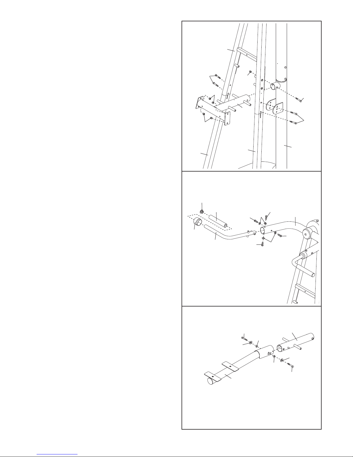
6. Attach the Support Frame (15) to the Upright
Base (3) with an M10 x 70mm Bolt (52) and an
M10 Nylon Locknut (44). Do not tighten the
Locknuts yet.
Attach the Support Frame (15) and the Left and
Right Legs (6, 7) to the Backrest Frame (8) with
four M10 x 50mm Bolts (48) and four M10 Nylon
Locknuts (44).
Tighten the M10 Nylon Locknuts (44) and M8 x
15mm Screws (51) used in steps 2–6.
7. Attach a Pull-up Handle (13) inside the Top
Frame (5) with four M8 x 19mm Screws (38) and
four M8 Curve Washers (39).
Slide a 57mm Round Outer Cap (23) onto the
Pull-up Handle (13) and press the Cap into the
Top Frame (5).
Wet the Pull-up Handle (13) with soapy water.
Slide a Long Handgrip (37) onto the Handle.
Press a 25mm Round Inner Cap (31) into the
Handle.
Repeat this step on the other side of the Top
Frame (5).
8
6
7
7
15
44
44
44
52
48
48
63
31
39
39 38
38
38
38
37
23
5
13
8. Attach the Pad Frame (10) to the Pivot Arm (9)
with two M8 x 19mm Screws (38), two M8
Washers (46), and two 15mm Spacers (34).
10
34
34
46
38
9
8
46
38
9
11. Slide two Resistance Bands (19) onto the indicat-
ed tubes on the Support Frame (15) and Pivot
Arm (9).
Attach the Cable (33) to the Support Frame (15)
and Pivot Arm (9) with two M8 x 25mm Screws
(41). Make sure that the cable ends pivot
freely on the Bolts.
10. Attach a Pin (18) to the Upright Base (3) with an
M4 x 19mm Screw (45).
Attach the Pivot Arm (9) to the Upright Base (3)
with the Pin (18). Make sure the Pin is inserted
all the way through the Upright Base and
Pivot Arm.
10
11
18
45
3
9
33
41
19 19
15
9
41
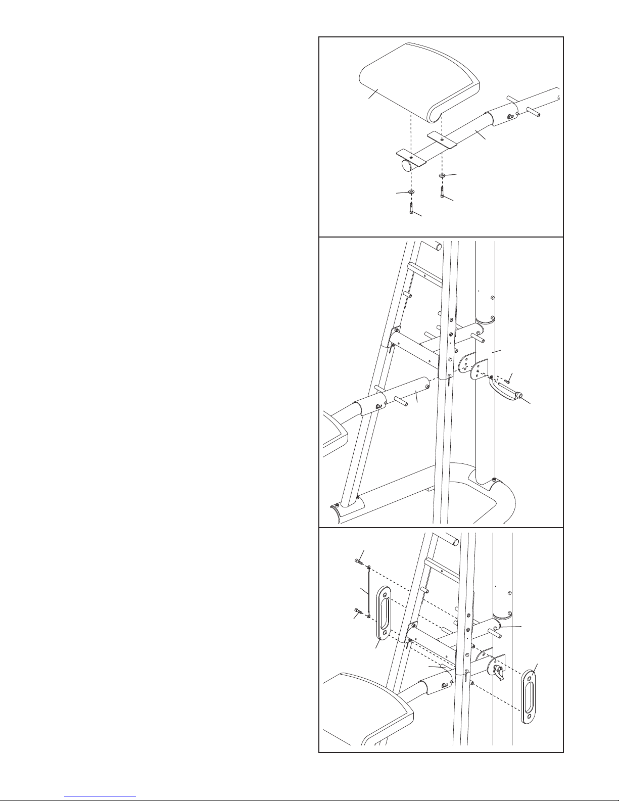
9. Attach the Knee Pad (21) to Pad Frame (10) with
two M6 x 75mm Screws (35) and two M6
Washers (36).
9
10
21
36
36
35
35

10
12. Hold the Dip Arm (11) behind the Backrest Frame
(8) as shown. Attach the Dip Arm to the Backrest
Frame with two M10 x 100mm Bolts (43) and two
M10 Nylon Locknuts (44). Do not overtighten
the Locknuts; the Dip Arm must be able to
pivot easily.
14. Tighten a Knob (24) into the Dip Arm (11).
Press a Dip Arm Bushing (30) into the Dip Arm
(11).
Pull the Knob (24) out as far as it will go. Slide
the Dip Handle (12) into the Dip Arm (11). Engage
the Knob into the Dip Handle.
Repeat this step on the other side of the Dip
Arm (11).
13. Attach the Right Pad Base (27) and an Arm Pad
(25) to the Dip Arm (11) with two M6 x 75mm
Screws (35) and two M6 Washers (36).
Repeat this step with the Left Pad Base (26)
and the other Arm Pad (25).
11
43
44
8
11
27
35
36
36
25
25
26
11
24
30
12
43
12
13
14

11
15. Attach the Fin (14) to the Upright (4) and Support
Frame (15) with three M4 x 19mm Screws (45).
17. Attach the Backrest (22) to the Backrest Frame
(8) with an M6 x 38mm Screw (50) and an M6
Washer (36).
Attach the Backrest (22) to the Support Frame
(15) with two M6 x 75mm Screws (35) and two
M6 Washers (36).
18. Make sure that all parts have been properly
tightened before the exercise rack is used.
16. Attach a Pin (18) to the Backrest Frame (8) with
an M4 x 19mm Screw (45).
Insert the Pin (18) into the Backrest Frame (8).
14 4
15
45
45
45
18
8
50
36
22
36
36
35
35
8
15
15
16
17

This section explains how to adjust the exercise rack. See the EXERCISE GUIDELINES on page 14 for impor-
tant information about how to get the most benefit from your exercise program. Also, refer to the accompanying
exercise guide to see the correct form for each exercise.
Make sure all parts are properly tightened each time the exercise rack is used. Replace any worn parts immediate-
ly. The exercise rack can be cleaned with a damp cloth and a mild, non-abrasive detergent. Do not use solvents.
12
ADJUSTING THE DIP HANDLE
The Dip Handle (12) can be rotated 90 degrees. Pull
out the Knob (24) as far as it will go. Rotate the Dip
Handle to the desired position and reengage the
Knob.
The Dip Handle (12) can also be adjusted to three
lengths. Pull out the Knob (24) as far as it will go.
Move the Dip Handle to the desired length and reen-
gage the Knob.
11
9
Hold
Here
3
18
24
12
ADJUSTING THE DIP ARM
To perform some exercises, the Dip Arm (11) should
be locked in the up position. Remove the indicated
Pin (18) and lift the Dip Handle (12). Engage the Pin
into the Backrest Frame (8) and the hole in the Dip
Arm plate.
To use the Dip Arm (11), remove the Pin (18) and
lower the Dip Handle (12). Insert the Pin into the
Backrest Frame (8).
ADJUSTING THE KNEE PAD
To change the pivot angle of the knee pad, first make
sure the there are at least two resistance bands
assembled on the Pivot Arm (9) (see USING RESIS-
TANCE BANDS on page 13). Next, hold the Pivot
Arm in the indicated location and remove the indicat-
ed Pin (18). Then, align the hole in the Pivot Arm with
the desired hole in the Upright Base (3). Finally, reen-
gage the Pin into the Upright Base and Pivot Arm.
12
18
8
WARNING: Always make sure that
the Knob (24) is engaged into a hole in the Dip
Handle (12).
ADJUSTMENTS

13
21
19
21
34
ADJUSTING THE KNEE PAD
To adjust the Knee Pad (21) to the up position, lift on
the Knee Pad so that the rod on the Pivot Arm (9) is
in the notch in the Pad Frame (10). Then lower the
Knee Pad so that the 15mm Spacers (34) are in the
top of the “L”-slot in the Pad Frame (10).
To adjust the Knee Pad (21) to the down position, lift
on the Knee Pad and slide the Pad Frame forward,
disengaging the rod on the Pivot Arm (9). Lower the
Knee Pad.
Storage
Tube
10
9
Rod
“L”-slot
Notch
9
15
USING THE RESISTANCE BANDS
To add resistance to the Pivot Arm (9), slide a
Resistance Band (19) onto the tubes on the Pivot Arm
and the Support Frame (15).
Refer to the chart on the Fin (14) to determine how
many Resistance Bands (19) should be used.
Resistance Bands can be stored on the storage tube
when not being used.
14
WARNING: Never use the Knee
Pad (21) without at least one Resistance Band
(19) connecting the Support Frame (15) to the
Pivot Arm (9).

EXERCISE GUIDELINES
THE FOUR BASIC TYPES OF WORKOUTS
Muscle Building
To increase the size and strength of your muscles,
push them close to their maximum capacity. Your mus-
cles will continually adapt and grow as you progres-
sively increase the intensity of your exercise. You can
adjust the intensity level of an individual exercise in
two ways:
• by changing the amount of resistance used
• by changing the number of repetitions or sets per-
formed. (A “repetition” is one complete cycle of an
exercise, such as one sit-up. A “set” is a series of
repetitions.)
The proper amount of resistance for each exercise
depends upon the individual user. You must gauge
your limits and select the amount of resistance that is
right for you. Begin with 3 sets of 8 repetitions for each
exercise you perform. Rest for 3 minutes after each
set. When you can complete 3 sets of 12 repetitions
without difficulty, increase the amount of resistance.
Toning
You can tone your muscles by pushing them to a mod-
erate percentage of their capacity. Select a moderate
amount of resistance and increase the number of rep-
etitions in each set. Complete as many sets of 15 to
20 repetitions as possible without discomfort. Rest for
1 minute after each set. Work your muscles by com-
pleting more sets rather than by using high amounts of
resistance.
Weight Loss
To lose weight, use a low amount of resistance and
increase the number of repetitions in each set.
Exercise for 20 to 30 minutes, resting for a maximum
of 30 seconds between sets.
Cross Training
Cross training is an efficient way to get a complete and
well-balanced fitness program. An example of a bal-
anced program is:
• Plan strength training workouts on Monday,
Wednesday, and Friday.
• Plan 20 to 30 minutes of aerobic exercise, such as
running on a treadmill or riding on an elliptical or
exercise bike, on Tuesday and Thursday.
• Rest from both strength training and aerobic exercise
for at least one full day each week to give your body
time to regenerate.
The combination of strength training and aerobic exer-
cise will reshape and strengthen your body, plus devel-
op your heart and lungs.
PERSONALIZING YOUR EXERCISE PROGRAM
Determining the exact length of time for each workout,
as well as the number of repetitions or sets completed,
is an individual matter. It is important to avoid overdo-
ing it during the first few months of your exercise pro-
gram. You should progress at your own pace and be
sensitive to your body’s signals. If you experience pain
or dizziness at any time while exercising, stop immedi-
ately and begin cooling down. Find out what is wrong
before continuing. Remember that adequate rest and a
proper diet are important factors in any exercise pro-
gram.
WARMING UP
Begin each workout with 5 to 10 minutes of stretching
and light exercise to warm up. Warming up prepares
your body for more strenuous exercise by increasing
circulation, raising your body temperature and deliver-
ing more oxygen to your muscles.
WORKING OUT
Each workout should include 6 to 10 different exercis-
es. Select exercises for every major muscle group,
emphasizing areas that you want to develop most. To
give balance and variety to your workouts, vary the
exercises from session to session.
Schedule your workouts for the time of day when your
energy level is the highest. Each workout should be
followed by at least one day of rest. Once you find the
schedule that is right for you, stick with it.
EXERCISE FORM
Maintaining proper form is an essential part of an
effective exercise program. This requires moving
through the full range of motion for each exercise, and
moving only the appropriate parts of the body.
Exercising in an uncontrolled manner will leave you
feeling exhausted. On the exercise guide accompany-
ing this manual you will find photographs showing the
correct form for several exercises, and a list of the
muscles affected. Refer to the muscle chart on the
next page to find the names of the muscles.
The repetitions in each set should be performed
smoothly and without pausing. The exertion stage of
each repetition should last about half as long as the
return stage. Proper breathing is important. Exhale
during the exertion stage of each repetition and inhale
during the return stroke. Never hold your breath.
14

15
Rest for a short period of time after each set. The
ideal resting periods are:
• Rest for three minutes after each set for a muscle
building workout.
• Rest for one minute after each set for a toning work-
out.
• Rest for 30 seconds after each set for a weight loss
workout.
Plan to spend the first couple of weeks familiarizing
yourself with the equipment and learning the proper
form for each exercise.
COOLING DOWN
End each workout with 5 to 10 minutes of stretching.
Include stretches for both your arms and legs. Move
slowly as you stretch and do not bounce. Ease into
each stretch gradually and go only as far as you can
without strain. Stretching at the end of each workout
is an effective way to increase flexibility.
STAYING MOTIVATED
For motivation, keep a record of each workout. List the
date, the exercises performed, the resistance used,
and the numbers of sets and repetitions completed.
Record your weight and key body measurements at
the end of every month. Remember, the key to achiev-
ing the greatest results is to make exercise a regular
and enjoyable part of your everyday life.
O
P
Q
R
S
T
U
V
X
W
N
M
J
G
F
H
I
K
E
C
D
B
A
L
MUSCLE CHART
A. Sternomastoid (neck)
B. Pectoralis Major (chest)
C. Biceps (front of arm)
D. Obliques (waist)
E. Brachioradials (forearm)
F. Hip Flexors (upper thigh)
G. Abductor (outer thigh)
H. Quadriceps (front of thigh)
I. Sartorius (front of thigh)
J. Tibialis Anterior (front of calf)
K. Soleus (front of calf)
L. Anterior Deltoid (shoulder)
M. Rectus Abdominus (stomach)
N. Adductor (inner thigh)
O. Trapezius (upper back)
P. Rhomboideus (upper back)
Q. Posterior Deltoid (shoulder)
R. Triceps (back of arm)
S. Latissimus Dorsi (mid back)
T. Spinae Erectors (lower back)
U. Gluteus Medius (hip)
V. Gluteus Maximus (buttocks)
W. Hamstring (back of leg)
X. Gastrocnemius (back of calf)

M6 Washer (36)
M10 x 50mm Bolt (48)
M8 Curve Washer (39)
M8 Washer (46)
M10 Nylon Locknut (44)
M10 x 70mm Bolt (52)
M10 x 140mm Bolt (47)
M10 x 100mm Bolt (43)
M8 x 19mm Screw (38)
M8 x 15mm Screw (51)
M8 x 25mm Screw (41)
M6 x 75mm Screw (35)
M6 x 38mm Screw (50)
M4 x 19mm Screw (45)
M4 x 16mm Screw (42)
M3 x 30mm Screw (49)
PART IDENTIFICATION CHART
Refer to the drawings below to identify small parts used in assembly. The number in parentheses by each draw-
ing is the key number of the part, from the PART LIST in the center of this manual. Note: Some small parts
may have been pre-attached. If a part is not in the parts bag, check to see if it has been pre-attached.

Note: “#” indicates a non-illustrated part. Specifications are subject to change without notice. See the back cover
of the user’s manual for information about ordering replacement parts.
Key No. Qty. Description Key No. Qty. Description
1 1 Base
2 2 Base Handle
3 1 Upright Base
41 Upright
5 1 Top Frame
6 1 Left Leg
7 1 Right Leg
8 1 Backrest Frame
9 1 Pivot Arm
10 1 Pad Frame
11 1 Dip Arm
12 2 Dip Handle
13 2 Pull-up Handle
14 1 Fin
15 1 Support Frame
16 2 Base Cap
17 2 Base Pad
18 2 Pin
19 4Resistance Band
20 1 57mm Round Inner Cap
21 1Knee Pad
22 1 Backrest
23 2 57mm Round Outer Cap
24 2 Knob
25 2 Arm Pad
26 1 Left Pad Base
27 1 Right Pad Base
28 2Front Handle Cap
29 2 Rear Handle Cap
30 2 Dip Arm Bushing
31 6 25mm Round Inner Cap
32 2 Dip Handgrip
33 1 Cable
34 2 15mm Spacer
35 8 M6 x 75mm Screw
36 9 M6 Washer
37 4 Long Handgrip
38 10 M8 x 19mm Screw
39 8 M8 Curve Washer
40 1 Top Frame Cap
41 2 M8 x 25mm Screw
42 2 M4 x 16mm Screw
43 10 M10 x 100mm Bolt
44 16 M10 Nylon Locknut
45 6 M4 x 19mm Screw
46 2 M8 Washer
47 1M10 x 140mm Bolt
48 4 M10 x 50mm Bolt
49 4M3 x 30mm Screw
50 1 M6 x 38mm Screw
51 2 M8 x 15mm Bolt
52 1 M10 x 70mm Bolt
# 1 User’s Manual
# 1 Exercise Guide
# 3 Allen Wrench
PART LIST—Model No. EPBE22040 R1204A

47
8
43
48
48
43
44
44
18
45
6
7
44
44
44
44
19
19
21
20
10
36
35
35
36
9
38
46
38
34
46
34
22
50
36
36
36
35
31
31
32
12
12
32
28
28
37
31
37
31
29
30
24
27
25
11
36
35
36
35
30
29
24
26
25
49
49
49
49
EXPLODED DRAWING—Model No. EPBE22040 R1204A

2
2
43
43
16
16
1
17
17
42
42 43
44
43
3
44
18
45
52
44
44
15
45
33
41
41
31
37
13 45
45
23
14
4
51
51
44
5
23
45 40
13
37
31
39
38
38
38
38
38
38
39
38
39
38
39

LIMITED WARRANTY
ICON Health & Fitness, Inc. (ICON), warrants this product to be free from defects in workmanship and
material, under normal use and service conditions, for a period of ninety (90) days from the date of pur-
chase. This warranty extends only to the original purchaser. ICON's obligation under this warranty is lim-
ited to replacing or repairing, at ICON's option, the product through one of its authorized service centers.
All repairs for which warranty claims are made must be pre-authorized by ICON. This warranty does not
extend to any product or damage to a product caused by or attributable to freight damage, abuse, mis-
use, improper or abnormal usage or repairs not provided by an ICON authorized service center; products
used for commercial or rental purposes; or products used as store display models. No other warranty
beyond that specifically set forth above is authorized by ICON.
ICON is not responsible or liable for indirect, special or consequential damages arising out of or in con-
nection with the use or performance of the product or damages with respect to any economic loss, loss
of property, loss of revenues or profits, loss of enjoyment or use, costs of removal or installation or other
consequential damages of whatsoever nature. Some states do not allow the exclusion or limitation of inci-
dental or consequential damages. Accordingly, the above limitation may not apply to you.
The warranty extended hereunder is in lieu of any and all other warranties and any implied warranties of
merchantability or fitness for a particular purpose is limited in its scope and duration to the terms set forth
herein. Some states do not allow limitations on how long an implied warranty lasts. Accordingly, the above
limitation may not apply to you.
This warranty gives you specific legal rights. You may also have other rights which vary from state to state.
ICON HEALTH & FITNESS, INC., 1500 S. 1000 W., LOGAN, UT 84321-9813
Part No. 219402 R1204A Printed in China © 2004 ICON IP, Inc.
To order replacement parts, simply call our Customer Service Department toll-free at 1-866-997-6999, Monday
through Friday, 6 a.m. until 6 p.m. Mountain Time (excluding holidays). To help us assist you, please be pre-
pared to give the following information:
1. The MODEL NUMBER of the product (EPBE22040)
2. The NAME of the product (EPIC®V150 STRONGHOLD exercise rack)
3. The SERIAL NUMBER of the product (see the front cover of this manual)
4. The KEY NUMBER and DESCRIPTION of the part(s) (see the PART LIST and EXPLODED DRAWING at the
center of this manual)
ORDERING REPLACEMENT PARTS
This manual suits for next models
2
Table of contents
Other Epic Fitness Fitness Equipment manuals


Popular Fitness Equipment manuals by other brands


G-FITNESS
G-FITNESS AIR ROWER user manual

CAPITAL SPORTS
CAPITAL SPORTS Dominate Edition 10028796 manual

Martin System
Martin System TT4FK user guide

CIRCLE FITNESS
CIRCLE FITNESS E7 owner's manual

G-FITNESS
G-FITNESS TZ-6017 user manual

Accelerated Care Plus
Accelerated Care Plus OMNISTIM FX2 CYCLE/WALK user manual


