Hioki SP7150 User manual

Instruction Manual
EN
July 2021 Revised edition 1
SP7001A961-01 21-07H
Be sure to read this manual before using the instrument. p.7
When using the instrument for the
rst time Troubleshooting
Part Names and Functions p.10 Maintenance and Service p.43
Preparing Before Use p.15
Functionality p.27
SP7001
SP7002
NON-CONTACT CAN SENSOR
SP7150
CAN INTERFACE
SP7100
SP9250
SIGNAL PROBE
SP9200
HIOKI SP7001A961-01

HIOKI SP7001A961-01

i
4 Specications 31
4.1 SP7001/SP7002 Non-Contact
CAN Sensor ..........................................31
4.2 SP7100 CAN Interface ........................34
4.3 SP7150 CAN Interface ........................37
4.4 SP9200 Signal Probe ..........................40
4.5 SP9250 Signal Probe ..........................41
4.6 SP9900 Split Cable
(dedicated option for SP7100)............42
5 Maintenance and Service43
5.1 Troubleshooting ....................................45
CAN signal detection is unstable. ..............45
You are unable to detect CAN signals
stably when using the product in an
environment where it is exposed to
vibrations, for example in road testing........46
Contents
Introduction........................................................1
About the Notations Used in This Manual.....2
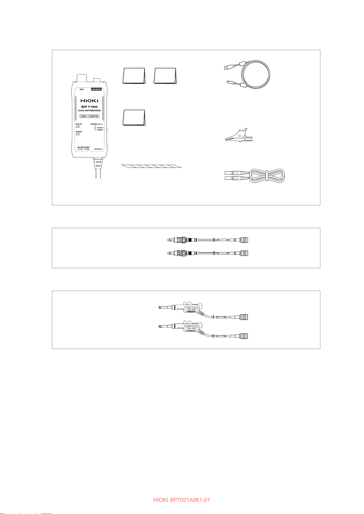
Verifying Package Contents............................3
Options.......................................................5
Operating Precautions .....................................7
1 Overview 9
1.1 Product Overview and Features...........9
1.2 Part Names and Functions .................10
SP7001/SP7002 Non-Contact CAN
Sensor .....................................................10
SP7100 CAN Interface..............................11
SP7150 CAN Interface..............................12
SP9200 Signal Probe................................13
SP9250 Signal Probe................................13
1.3 LED Lighting/Flashing
Specications........................................14
2 Preparing Before Use 15
2.1 Preparations..........................................15
2.2 Connecting the Signal Probes............16
2.3 Connecting the Non-Contact CAN
Sensor....................................................17
2.4 Connecting the Ground Terminal .......18
2.5 Connecting the CAN Interface............20
2.6 Supplying Power...................................21
2.7 Connecting the Signal Probes to
the CAN bus..........................................22
When using the SP9200 ...........................22
When using the SP9250 ...........................24
2.8 Inspecting the Product Before Use ....25
3 Functionality 27
3.1 Switching the Non-Contact CAN
Sensor’s Signal Detection
Sensitivity...............................................27
3.2 Probe Setting Function
(Automatic Polarity Selection) ............28
3.3 Output Bus Error Detection
Function .................................................29
SP7001A961-01
HIOKI SP7001A961-01

Contents
ii
HIOKI SP7001A961-01

1
Introduction
Introduction
Thank you for choosing the Hioki SP7001/SP7002 Non-Contact CAN Sensor, SP7100/SP1750
CAN Interface, and SP9200/SP9250 Signal Probe. Keep this manual accessible so that you can
take full advantage of the product’s functionality throughout its service life.
Be sure to review the following documentation before using the product:
Document Content Paper edition Electronic
edition
Instruction Manual
(this manual)
The Instruction Manual contains detailed
instructions about how to use the
product.
The most recent version can be
downloaded from Hioki’s website.
–
Quick Start Manual The Quick Start Manual provides a brief
overview of how to use the product. –
Operating Precautions
(0990A905)
“Operating Precautions” contains
important information about how to use
the product safely.
–
Familize yourself with the separate document entitled Operating Precautions and Quick Start
Manual before using the product.
Communications standards
The Non-Contact CAN Sensor supports the following communications standards:
Model Communications standards
SP7001
SP7002 –
Target audience
This Instruction Manual has been written for users of the product and individuals who will instruct
others on how to use the product.
It assumes that the reader has basic knowledge about electricity (at the level one would obtain from
completing an electrical program at a technical high school).
Use of the product
Before using the product, review proper handling of the product, bus systems, and related systems.
Only individuals who understand both safe product use and the potential impacts arising from
using the product should use the product. Use of the product by others may cause bodily injury or
damage to the product or other devices.
HIOKI SP7001A961-01

2
About the Notations Used in This Manual
Safety notations
This manual classies seriousness of risks and hazard levels as described below.
WARNING Indicates the possibility of serious injury or death.
CAUTION Indicates the likelihood of minor injury or equipment damage or failure.
IMPORTANT Indicates information or content that is particularly important from the standpoint
of operating or maintaining the product.
Indicates useful advice concerning product performance and operation.
Indicates an action that must not be performed.
Indicates an action that must be performed.
Symbols on equipment
Indicates the need for caution or the presence of a hazard. For more information
about locations where this symbol appears on product components, see “Operating
Precautions” (p.7), warning messages listed at the beginning of operating
instructions, and the document entitled “Operating Precautions” that comes with the
product.
Symbols related to standards
Indicates compliance with the Waste Electrical & Electronic Equipment (WEEE)
Directive in EU member countries.
Indicates compliance with EU directives.
Other symbols
*Instructs the reader to see below for more information.
(p. ) Indicates the page number to reference.
Bold Operation keys are printed in bold.
HIOKI SP7001A961-01

3
Verifying Package Contents
Before using the product, inspect it for any damage that may have occurred during shipment.
Exercise particular care with regard to accessories, panel switches, and terminals. Contact your
authorized Hioki distributor or reseller if you nd any damage or if the product fails to operate to its
specications.
SP7001/SP7002 Non-Contact CAN Sensor
SP7001 ×1 SP7002 ×1
or
Quick Start Manual
Japanese and English ×1 each
Operating Precautions (0990A905) ×1
SP7100 CAN Interface
SP7100 ×1
L9500 Power Cable ×1
(For connecting an external battery;
terminates in wires; approx. 2 m long)
Refer to p.21.
Spiral tube ×1
(For securing the power cable in place)
Refer to p.21.
Alligator clip ×1
Refer to p.18.
Ground connection cable (1.5 m) ×1
Refer to p.18.
Quick Start Manual
Japanese and English ×1 each
Operating Precautions (0990A905) ×1
HIOKI SP7001A961-01

4
Verifying Package Contents
SP7150 CAN Interface
SP7150 ×1
Quick Start Manual
Japanese and English ×1 each
Operating Precautions (0990A905) ×1
L9510 USB Cable ×1
(Type-A Type-C; for power supply;
1 m long)
Refer to p.21.
Spiral tube ×1
(For securing the power cable in place)
Refer to p.21. Ground connection cable (1.5 m) ×1
Refer to p.18.
Alligator clip ×1
Refer to p.18.
SP9200 Signal Probe
Signal Probe ×2
SP9250 Signal Probe
Signal Probe ×2
HIOKI SP7001A961-01

5
Verifying Package Contents
Options
The following options are available for the product. To purchase an option, please contact your
Hioki’s distributor or reseller.
Options are subject to change. Please check Hioki’s website for the latest information.
SP7001 Non-Contact CAN Sensor
Refer to p.17.
SP7002 Non-Contact CAN Sensor
Refer to p.17.
SP7100 CAN Interface
Refer to p.20.
SP7150 CAN Interface
Refer to p.20.
SP9200 Signal Probe
Refer to p.16.
SP9250 Signal Probe
Refer to p.16.
HIOKI SP7001A961-01

6
Verifying Package Contents
Z1008 AC Adapter (for SP7100 only)
Refer to p.21.
Z1013 AC Adapter (for SP7150 only)
Refer to p.21.
L9500 Power Cable (for SP7100 only)
(For connecting an external battery; terminates in wires;
approx. 2 m long)
Refer to p.21.
L9510 USB Cable (for SP7150 only)
(Type-A Type-C; for power supply; 1 m long)
Refer to p.21.
SP9900 Split Cable (for SP7100 only)
Refer to p.20.
C1013 Carrying Case
Options can be purchased via authorized Hioki distributor or reseller.
HIOKI SP7001A961-01

7
Operating Precautions
Be sure to observe the following precautionary information to ensure that the product can be used
safely and in a manner that allows it to perform as described in its specications. Use of the product
should conform not only to its specications, but also to the specications of all accessories,
options, and other equipment in use.
Handling of the product
WARNING
Do not use the product in locations such as those listed below. Doing so may
result in product damage or cause an accident.
•Locations where the product would be subject to direct sunlight or high
temperatures
•Locations where corrosive or explosive gases are present
•Locations where there is powerful electromagnetic radiation or that are close to
electrically charged objects
•Close to inductive heating equipment (high-frequency inductive heating
equipment, IH cooktops, etc.)
•Locations with an excessive amount of mechanical vibration
•Locations where the product would be exposed to water, oil, chemicals,
solvents, or other liquids
•Locations with excessive humidity or condensation
•Locations with excessive dust
CAUTION
• Do not drop the product or subject it to mechanical shock.
Doing so may damage the product and adversely affecting its detection performance.
• Do not handle the product’s connectors with your bare hands or manipulate them with
tools.
Subjecting connectors to excessive force may damage them.
• Do not connect the product to cables (CAN bus lines) other than those described in
the specications.
Doing so may damage the cable under test.
• The product complies with EN 61326 Class A. Use in residential settings such as neighborhoods
may cause radio or television interference. If you encounter such interference, take appropriate
steps to prevent it.
• When transporting the product, take care to avoid subjecting it to vibration or mechanical shock.
HIOKI SP7001A961-01

8
Operating Precautions
Cables
CAUTION
• To avoid damaging their insulation, do not step on or pinch the product’s cables.
• Do not place foreign objects in the guard hook (p.13).
Doing so may cause issues with signal detection or opening/closing operation of the
product.
• Cables harden in freezing temperatures. Exercise care as bending or pulling on
cables under such conditions can damage insulation and cause wiring breaks.
• Attach the signal probe to the cable under test after checking the cable for
deteriorated or damaged insulation.
The product detects CAN signals such as those used to communicate with ECUs in a
contactless manner from outside the cable insulation. Any electrical short between the
signal probe and cable wires could interfere with CAN communications.
• To prevent damage to the product’s special vibration-resistant connectors, always
disengage the lock and grip the connector itself (not the cable) when disconnecting
them.
Refer to “2.2 Connecting the Signal Probes” (p.16).
Z1008/Z1013 AC Adapter
WARNING
• The Z1008/Z1013 AC Adapter has a rated supply voltage of 100 V to 240 V and a
rated frequency of 50 Hz or 60 Hz. To prevent damage to the product or an electric
accident, never use the adapter with any other voltage.
• To prevent electric shock and ensure safety, connect the included power cord to a
grounded two-prong outlet.
HIOKI SP7001A961-01

9
1Overview
1.1 Product Overview and Features
The SP7001/SP7002 Non-Contact CAN Sensor can detect CAN communications signals, which
are used in control communications in automobiles and in a variety of devices, from outside cables’
insulation.
Captured CAN signals can be connected to analyzers, loggers, and other measuring instruments
with a CAN interface.
Engine BatteryMotor
Radar Airbag Brake
ECU ECU
ECU ECU ECU
ECU ECUECU
ECU ECU
Electrical
System
Instrument
Panel
Contactless sensing that doesn’t affect the system under test
The Non-Contact CAN Sensor uses proprietary technology to detect CAN communications signals from
outside cables’ insulation. As a result, there is no need to attach connectors or to connect or fabricate wire
harnesses (cable harnesses) in order to acquire signals.
Since the Non-Contact CAN Sensor is electrically isolated from the CAN bus whose signals are being
detected, use of the product has no effect on the electrical characteristics of the system under test. Products
can be tested in their nished or mass-produced state.
Reliable detection
Detection defects have been minimized to avoid errors caused by the Non-contact CAN Sensor and detected
by devices such analyzers, facilitating accurate* automobile development and evaluating testing. Additionally,
infrequent events can be reliably detected.
CAN and CAN FD support
The Non-Contact CAN Sensor supports high-speed CAN communications at speeds ranging from 125 kbit/s
to 1 Mbit/s. Additionally, the product can detect CAN FD communications at up to 3 Mbit/s.
Support for a variety of CAN input devices
The Non-Contact CAN Sensor uses standard D-sub 9-pin terminals for its output connectors. As a result, you
can connect analyzers, loggers, instruments, and other devices with a CAN interface.
*: The Non-Contact Sensor is capable of extremely stable CAN frame acquisition. However, the product
is not guaranteed to achieve an error rate of 0% under all conditions. Errors may be caused by factors
including the condition of the vehicle being tested and the quality of the power supply being used. Please
verify that the product functions properly with the vehicle to be tested prior to use.
1 Overview
HIOKI SP7001A961-01

10
Part Names and Functions
1.2 Part Names and Functions
SP7001/SP7002 Non-Contact CAN Sensor
77
66
44
22
Front Rear
33
: SP7002
: SP7001
11
55(Pictured: SP7001)
No. Name Function See
1HIGH Signal Probe
connector
Connect a Signal Probe.
Connect the other end of Signal Probe to the CAN bus’s CAN_H line.
p.16
p.22
2LOW Signal Probe
connector
Connect a Signal Probe.
Connect the other end of Signal Probe to the CAN bus’s CAN_L line.
p.16
p.22
3STATUS LED Indicates the status of the Non-contact CAN Sensor. p.14
4SENSITIVITY
selector
Sets the Non-Contact CAN Sensor’s sensitivity to either DEFAULT
(normal mode) or HIGH (high-sensitivity mode).
Ordinarily, the product should be used with the DEFAULT setting.
p.27
5 Output connector Connect to the CAN Interface’s Non-Contact CAN Sensor connector. p.17
6 Ground terminal
If connecting the CAN interface’s ground terminal to the ground
cannot reduce the noise, connect this terminal to the CAN signal
source’s ground or to the automobile’s body (ground or body ground
connected to the vehicle battery’s negative terminal). To prevent
a short-circuit, the connector is AC-coupled to the CAN interface
ground.
p.18
7 Serial number
The 9-digit serial number indicates the year of manufacture (rst two
digits) and the month of manufacture (second two digits).
Do not remove this sticker as the number is important.
–
HIOKI SP7001A961-01

11
Part Names and Functions
SP7100 CAN Interface
44
11
77
22
55
33
Front Rear Right side
66
55
88
No. Name Function See
1 Ground terminal
Connect to the CAN signal source ground or to the automobile’s body
(ground or body ground connected to the vehicle battery’s negative
terminal).
p.18
2Non-Contact CAN
Sensor connector
Connect the SP7001/SP7002 Non-Contact CAN Sensor’s output
connector. p.17
3CAN SENSOR LED
CH1, CH2
Indicates the status of the Non-Contact CAN Sensors by mirroring
the state of the STATUS LEDs on the Non-Contact CAN Sensors
connected to CH1 and CH2.
p.14
4 Serial number
The 9-digit serial number indicates the year of manufacture (rst two
digits) and the month of manufacture (second two digits).
Do not remove this sticker as the number is important.
–
5 Probe setting selector
Sets the Non-Contact CAN Sensor’s probe setting function to either
AUTO or FIXED. Be sure to understand the functionality of AUTO
mode before using the sensor in that mode.
p.28
6CAN signal output
connector
This D-sub 9-pin female connector outputs the CAN signals from CH1
and CH2. p.20
7 Power jack Connect the L9500 Power Cable or Z1008 AC Adapter. p.21
8POWER LED Lights up when the product is on. p.14
HIOKI SP7001A961-01

12
Part Names and Functions
SP7150 CAN Interface
44
11
77
22
55
Front Rear Right side
66
55
88
33
No. Name Function See
1 Ground terminal
Connect to the CAN signal source ground or to the automobile’s body
(ground or body ground connected to the vehicle battery’s negative
terminal).
p.18
2Non-Contact CAN
Sensor connector
Connect the SP7001/SP7002 Non-Contact CAN Sensor’s output
connector. p.17
3STATUS LED Indicates the status of the Non-Contact CAN Sensor. p.14
4 Serial number
The 9-digit serial number indicates the year of manufacture (rst two
digits) and the month of manufacture (second two digits).
Do not remove this sticker as the number is important.
–
5 Probe setting selector
Sets the Non-Contact CAN Sensor’s probe setting function to either
AUTO or FIXED. Be sure to understand the functionality of AUTO
mode before using the sensor in that mode.
p.28
6CAN signal output
connector This D-sub 9-pin female connector outputs the CAN signal. p.20
7 Power jack Connect the L9510 USB Cable. p.21
8POWER LED Lights up when the product is on. p.14
HIOKI SP7001A961-01

13
Part Names and Functions
SP9200 Signal Probe
11
44
2233
No. Name Function See
1 Detection electrode Detects CAN signals from outside the cable’s insulation. p.22
2 Grip Rotate the grip to open and close the guard hook. p.22
3 Connector with lock Connect to the Non-Contact CAN Sensor. Be sure to verify that
the lock is engaged when connecting to the sensor. p.16
4 Guard hook Place the cable under test into the slit in the guard hook and
clamp it in place with the detection electrode. p.22
SP9250 Signal Probe
33
11
44
22
No. Name Function See
1 Detection electrode Detects CAN signals from outside the cable’s insulation. p.22
2 Open/close lever Push to open the guard hook. p.22
3 Connector with lock Connect to the Non-Contact CAN Sensor. Be sure to verify that
the lock is engaged when connecting to the sensor. p.16
4 Guard hook Place the cable under test into the slit in the guard hook and
clamp it in place with the detection electrode. p.22
HIOKI SP7001A961-01

14
LED Lighting/Flashing Specications
1.3 LED Lighting/Flashing Specications
SP7001/SP7002 Non-Contact CAN Sensor
Product status STATUS LED
Self-test error (failure) Steady red
Signal not detected Steady green
Signal detected Flashing green
Probe high/low reverse connection
warning Flashing red
SP7100/SP7150 CAN Interface
Product status POWER LED SP7100 SP7150
CH1, CH2 LED STATUS LED
Self-test error (failure) Flashing green Steady red
CAN sensor not connected Steady green Unlit
CAN sensor connected Steady green Reects CAN Sensor’s STATUS LED.
Output bus error detection Steady green Quickly alternating red/green
HIOKI SP7001A961-01

15
2Preparing Before Use
2.1 Preparations
IMPORTANT
Only remove the Signal Probe from the Non-Contact CAN Sensor when it needs to be replaced
due to wear. Leave the Signal Probe connected to prevent deterioration of the connector’s
contacts and to keep out dirt.
• For the SP7100
If pins for two channels have been allocated to the D-sub 9-pin connector you plan to use,
there is no need to use the SP9900 Split Cable. Check the pin assignments for the connector
you plan to use.
1
2
3
4
5
6
“2.2 Connecting the Signal
Probes” (p.16)
(Do not remove the Signal
Probe once it has been
connected.)
“2.6 Supplying Power”
(p.21)
“2.4 Connecting the
Ground Terminal”
(p.18)
“2.5 Connecting the CAN Interface” (p.20)
“2.7 Connecting the
Signal Probes to the CAN
bus” (p.22)
“2.3 Connecting the Non-
Contact CAN Sensor”
(p.17)
3
“2.4 Connecting the Ground
Terminal” (p.18)
Connection example:
Connect the SP7100 CAN Interface’s CAN signal output connector to the CAN interface-equipped
analyzer, logger, instrument, or other device with which you wish to use it.
2 Preparing Before Use
HIOKI SP7001A961-01

16
Connecting the Signal Probes
2.2 Connecting the Signal Probes
Connect to the Non-Contact CAN Sensor.
Connect the SP9200/SP9250 to the SP7001/SP7002 Non-Contact CAN Sensor’s signal probe
connector.
IMPORTANT
• Leave the Signal Probe connected to prevent deterioration of the Signal Probe and Non-
Contact CAN Sensor's connector’s contacts and to keep out dirt.
• The Signal Probe’s connector incorporates a locking mechanism. Always use the probe with
the connector in the locked state to ensure signals can be properly detected and to prevent
damage to the connector.
• Do not connect both the SP9200 and SP9250 to the same Non-Contact CAN Sensor. Doing
so may increase susceptibility to the effects of noise.
SP7001/SP7002
Non-Contact CAN Sensor
Example: SP9200 Signal Probe
SP7001 or SP7002
Signal Probe connector
SP9200 connector with lock
OK
NO
OK
NO
SP9200
SP9250
SP7001/SP7002
Non-Contact CAN Sensor
Insert until you hear a clicking
sound to lock the connector.
HIOKI SP7001A961-01
This manual suits for next models
5
Table of contents
Other Hioki Accessories manuals
Popular Accessories manuals by other brands

NETGEAR
NETGEAR AXM761 - ProSafe 10 Gigabit installation guide

Olympus
Olympus AS4000 - AS Transcription Kit instructions

netvox
netvox R718LB2 user manual

Disney
Disney DISNEY-BABY brochure

Freescale Semiconductor
Freescale Semiconductor KITMPR03xEVM quick start guide

Rittal
Rittal CMC III leak sensor Installation guide and short user's guide