3
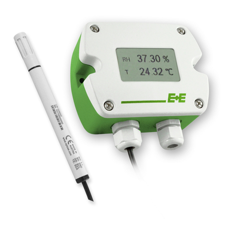
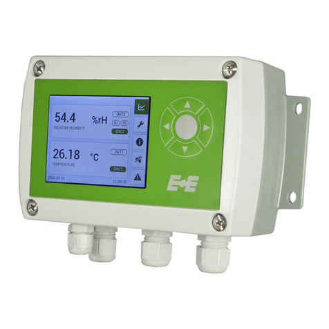
Operating inructions for EE310 Humidity / Temperature Transmitter
CONTENT
1 General .................................................................................................................................................4
1.1 Explanation of symbols .................................................................................................................................4
1.2 Safety inructions .........................................................................................................................................4
1.2.1 General safety inructions................................................................................................................................... 4
1.2.2 Alarm module with voltages >50 V (option AM2) ................................................................................................. 4
1.2.3 Integrated power supply 100...240 V AC (option AM3) ........................................................................................4
1.2.4 Mounting, art-up and operation .........................................................................................................................4
1.2.5 Intended Use........................................................................................................................................................5
1.2.6 Disclaimer ............................................................................................................................................................5
1.3 Environmental aspects ..................................................................................................................................5
1.4 ESD Protection..............................................................................................................................................5
2 Scope of supply...................................................................................................................................6
3 Product design ....................................................................................................................................6
3.1 Dimensions ...................................................................................................................................................7
3.1.1 Enclosure .............................................................................................................................................................7
3.1.2 Probes..................................................................................................................................................................7
4 Inallation............................................................................................................................................8
4.1 Mechanical inallation ..................................................................................................................................8
4.1.1 Mounting of the polycarbonate enclosure ............................................................................................................8
4.1.2 DIN rail mounting of the polycarbonate enclosure ...............................................................................................8
4.2 Electrical connection .....................................................................................................................................9
4.2.1 Electrical connection and wiring.........................................................................................................................10
4.3 Probe mounting (wall / duct version) ...........................................................................................................13
4.4 Mounting remote sensing probe of EE310-T5.............................................................................................13
4.5 Mounting pressure tight probe of EE310-T10 .............................................................................................14
4.5.1 Inallation of the probe directly in the process (see Fig. 10).........................................................14
4.5.2 Inallation of the probe with ball valve set......................................................................................................... 14
5 Optional modules ..............................................................................................................................16
5.1 Alarm module (option AM2).........................................................................................................................16
5.2 Integrated power supply 100...240 V AC (option AM3) ...............................................................................17
5.3 RS485 Module - Modbus RTU (option J3) ..................................................................................................18
5.4 Ethernet Module - Modbus TCP (option J4)................................................................................................18
5.4.1 Available TCP and UDP ports............................................................................................................................18
5.4.2 IPv4-Settings......................................................................................................................................................19
5.4.3 Retrot with Ethernet Module.............................................................................................................................20
5.5 Modbus Map................................................................................................................................................20
5.6 Pluggable probe (option PC4) .....................................................................................................................21
6 Operation ...........................................................................................................................................22
6.1 Conguration interface ................................................................................................................................22
6.2 3.5” TFT Colour Display ..............................................................................................................................23
6.3 Chart + Data logger ....................................................................................................................................23
6.4 Conguration Menu ...................................................................................................................................24
6.5 Status information ......................................................................................................................................25
6.6 Buzzer ON / OFF .......................................................................................................................................25
6.7 Error indication ...........................................................................................................................................25
7 Maintenance.......................................................................................................................................26
7.1 Self diagnosis and error messages .............................................................................................................26
7.1.1 Error messages via display................................................................................................................................26
7.1.2 Error messages via LEDs .................................................................................................................................. 26
7.1.3 Solving typical problems .................................................................................................................................... 27
7.2 Cleaning the sensing head / lter replacement ...........................................................................................27
7.3 RH / T adjument and calibration ...............................................................................................................27
8 Replacement parts / Accessories ....................................................................................................28
9 Technical data....................................................................................................................................29
10 Appendix ...........................................................................................................................................30
10.1 Overview .....................................................................................................................................................30
10.2 Detailed information ....................................................................................................................................30
10.3 Optional menu ............................................................................................................................................33


