3
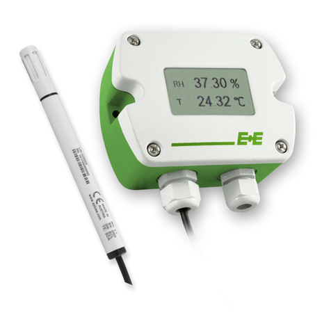
Operating instructions for EE360 Moisture in Oil Transmitter
CONTENT
1 General .................................................................................................................................................4
1.1 Explanation of symbols .................................................................................................................................4
1.2 Safety instructions .........................................................................................................................................4
1.3 Environmental aspects ..................................................................................................................................4
2 Product Description ............................................................................................................................5
2.1 Product design ..............................................................................................................................................5
2.2 Probes ...........................................................................................................................................................6
2.3 Water activity vs. water content.....................................................................................................................6
2.4 Indoor and Outdoor use ................................................................................................................................6
3 Installation ...........................................................................................................................................7
3.1 Mechanical installation ..................................................................................................................................7
3.1.1 Mounting of the polycarbonate enclosure ............................................................................................................7
3.1.2 DIN rail mounting of the polycarbonate enclosure ...............................................................................................7
3.2 Electrical connection .....................................................................................................................................8
3.2.1 Connection diagram M16.....................................................................................................................................8
3.2.2 Connection diagram Option E4 ......................................................................................................................... 10
3.2.3 Connection diagram Option E5..........................................................................................................................10
3.2.4 Connection diagram Options E6 and E12.......................................................................................................... 11
3.2.5 Connection diagram Conduit option...................................................................................................................12
3.2.6 Connection diagram for integrated power supply module AM3 ......................................................................... 14
3.2.7 Connection digram for integrated power supply module AM5 ........................................................................... 15
3.2.8 Connection diagram for alarm outputs AM2.......................................................................................................16
3.2.9 Connection diagram for alarm outputs AM6.......................................................................................................18
3.3 Probe mounting ...........................................................................................................................................19
3.3.1 Installation depth sliding fitting ........................................................................................................................... 19
3.3.2 Installation of the probe directly in the process with sliding fitting up to 20 bar .................................................20
3.3.3 Installation of the probe (sliding fitting up to 20 bar) with ball valve set ............................................................. 20
3.3.4 Installation of the probe with cut-in fitting up to 100 bar (1450 psi) ........................................................................ 22
4 Optional modules ..............................................................................................................................23
4.1 Alarm module (option AM2, AM6)................................................................................................................23
4.2 Integrated power supply 100...240 V AC (option AM3, AM5) ......................................................................25
4.3 RS485 Module - Modbus RTU (option J3) ..................................................................................................25
4.4 Modbus Map................................................................................................................................................26
5 Operation ...........................................................................................................................................27
5.1 Configuration interface ................................................................................................................................27
5.2 3.5” TFT Colour Display (optional) ..............................................................................................................28
5.3 Chart + Data logger ....................................................................................................................................28
5.4 Configuration Menu ...................................................................................................................................30
5.5 Status information ......................................................................................................................................30
5.6 Buzzer ON / OFF .......................................................................................................................................30
5.7 Error indication ...........................................................................................................................................30
6 Maintenance.......................................................................................................................................31
6.1 Self diagnosis and error messages .............................................................................................................31
6.1.1 Error messages via display................................................................................................................................31
6.1.2 Error messages via LEDs ..................................................................................................................................31
6.1.3 Solving typical problems ....................................................................................................................................32
6.2 Sensor replacement ....................................................................................................................................32
6.3 Cleaning the sensing head / filter replacement ...........................................................................................32
6.4 RH / T adjustment and calibration ...............................................................................................................33
7 Replacement Parts / Accessories....................................................................................................34
8 Scope of Supply ................................................................................................................................34
9 Technical Data ...................................................................................................................................35
10 Appendix ...........................................................................................................................................36
10.1 Appendix A ..................................................................................................................................................36
11 Ordering Guide ..................................................................................................................................41
11.1 Measurand Code.........................................................................................................................................41


