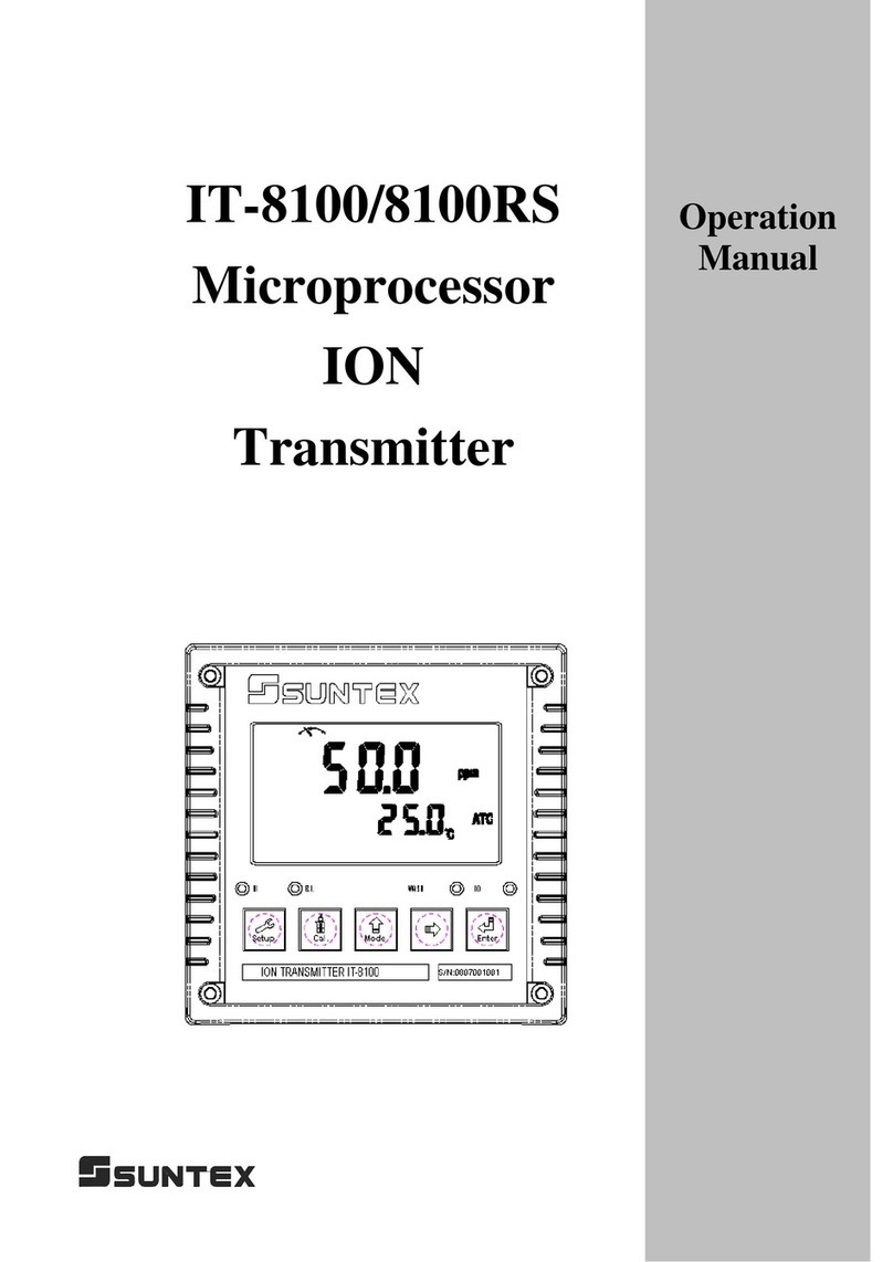
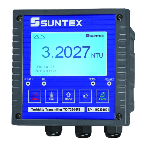
Suntex TC-7100 User manual

EnterMode
Cal.Setup
HI B.L. WASH LO
S/N:0811001001
Turbidity TRANSMITTER TC-7100
Operation
Manual
TC-7100
Microprocessor
Turbidity/S.S.
Transmitter

Brief Instruction 1
1. Specifications 6
2. Precautions for installation 7
3. Assembly and installation
3.1 Controller installation 7
3.2 Illustration of panel mounting 7
3.3 Illustration of Wall mounting and pipe mounting 8
4. Overview of Turbidity/Suspended Solids Transmitter TC-7100
4.1 Illustration of rear panel 9
4.2 Illustration of terminal function 9
4.3 Description of terminal function 10
4.4 Cable connection 10
4.5 Electrical connection diagram 11
5. Configuration
5.1 Illustration of front panel 12
5.2 Keypad 12
5.3 LED indicators 13
5.4 Display 13
6. Operation
6.1 Measurement mode 14
6.2 Set-up mode 14
6.3 Calibration mode 14
6.4 Reset 14
6.4.1 Master reset 14
6.4.2 Calibration reset 14
6.5 Time and date mode 14
7. Settings
Block diagram of settings 15
7.1 Entry of set-up mode 16
7.2 Security code of settings 16
7.3 Sensor model set-up 17
7.4 Measurement unit set-up 17
7.5 Hi point Setting 18
7.6 Lo point Setting 19
7.7 Automatic sensor scrub time interval set-up 20
7.8 Wash time 21
7.9 Analog output set-up 22
CONTENTS

7.10 Average signal transmission time set-up 23
7.11 Date/time set-up 23
7.12 RS-485 set-up 24
7.13 Backlight LCD 25
8. Calibration
Block diagram of Calibration 26
8.1 Security code of calibration 27
8.1.1 Authority of Security Code 27
8.1.2 Security Code Settings 27
8.2 Standard solution calibration—CT 28
8.3 Offset calibration—CA 30
9. RS-485
9.1 RS-485 wiring diagram 31
10. Error messages (Error code) 32
11. Maintenance 32

Brief Instruction
If you like to use security code of settings, the original code is 1111.
Settings of measurement parameters (see chapter 7)
In measurement mode, pressing “Setup"and “Mode"simultaneously
allows you to access Set-up mode.
Settings of Calibration (see chapter 8)
In measurement mode, pressing “Cal."and “Mode"simultaneously
allows you to access Calibration mode.
In the Code function, entering original code or user’s designated code allows you to
reset the code or shut down this function.
If you like to use security code of calibration, the original code is 1111.
In the Type function, please select a model type of sensor.
In the Code function, entering original code or user’s designated code allows you
to reset the code or shut down this function.
In the Configuration function, there is no function.
In the Relay 1 function, please select or to activate it or not.
In the Relay 2 function, please select or to activate it or not.
In the Clean function, please set wash time and stop duration.
In the Out function, please set analog output with or
In the Scrub function, please set sensor lens scrub time interval.
In the Unit function, please select correlated measurement unit.
In the Second function, please set average measurement reading time.
In the Serl function, please set MODBUS’s encoding, check bit, ID code and baud speed.
(
TC-7100RS onl
y)
In the Back light function, please set brightness of display and sensitivity of
light-source sensor.
In the Real time clock function, please set year, date, and time. (TC-7100RS only)
1

Note: “Ct 1” must be 0 NTU standard solution calibration.
Recommendation: Do not calibrate the value over 80% of measurement full scale.
進入模擬訊號顯示,等待數值顯示穩定後按 鍵,
開始校正。
4. The display shows Ct2 for entering the second point calibration.
Clean the sensor before immersing it into well-prepared standard
solution. Constantly stir the solution. Press to confirm it.
Enter turbidity range selection.
1. Enter CT1 Calbration mode. After cleaning up the sensor,
inmmerse the sensor into 0.00 NTU standard solutioin. Press
to confirm it. The display shows “0.00NTU”. Continually
press to send the calibration signal to sensor.
5. Enter turbidity range selection, press or to select
suitable range. Press and the value starts to twinkle. Press
or to adjust value until it is the same with the standard
solution’s value. Press to display the analog signal of the
sensor.
Two or up to five points calibration, and in which “Ct 1” must be 0 NTU calibration.
Offset calibration.
Turbidity standard solution 2 to 5 point calibration
2. At the time, the sensor responses 2 mA analog signal to indicate
that the sensor is in the process of inner calibration.
3. After inner calibration of the sensor, it responses 4 mA analog
signal to transmitter. Press to calibrate the sensor with the
0.00 NTU standard solution.
2

1. 螢幕顯示 CT4進入第四點校正,步驟同 4~6。
注:於顯示 CT4介面時按 鍵可以完成 3點
校正。直接跳至步
2. 螢幕顯示 CT5進入第五點校正,步驟同 4~6。
注:於顯示 CT5介面時按 鍵可以完成 4點
校正。直接跳至步驟 10。
7. The display shows Ct3 for entering the third point calibration. The
procedure is the same as step 4~6.
Note: To finish the calibration procedure as a two point
calibration, when the display shows Ct3 please press and
skip to step 10.
6. Enter analog signal display. Wait until the signal becomes stable,
then you may start the calibration.
8. The display shows Ct4 for entering the forth point calibration. The
procedure is the same as step 4~6.
Note: To finish the calibration procedure as a three point
calibration, when the display shows Ct4 please press and
skip to step 10.
3

3. 校正成功時,螢幕出現 CAL PASS 字樣,校正失
敗時,出現 CAL Err 訊息。(請參閱第十章錯誤訊
息,尋求原因及處理方法)
9. The display shows Ct5 for entering the fifth point calibration. The
procedure is the same as step 4~6.
Note: To finish the calibration procedure as a four point
calibration, when the display shows Ct5 please press and
skip to step 10.
10. When the calibration is successful, the display screen shows the
word “CAL PASS”; when the calibration is unsuccessful, the
display screen shows the word “CAL Err”. (Please refer to chapter
10 for error message, causes and treatment seeking.)
4

OffsetCalibration
註:執行偏移值校正前必須作過ㄧ次標準液校正後方可
執行偏移值校正。
Reset
Note: Before the implementation of offset calibration,
it is necessary to make a 2 to 5 points standard
solution calibration in advance.
4. When the calibration is successful, the display screen shows the
word “CAL PASS”; when the calibration is unsuccessful, the
display screen shows the word “CAL Err”. (Please refer to
1. After entering into display CA, put the sensor which has been
cleaned into turbidity standard solution, and constantly stir the
solution. Press to confirm and enter into turbidity range
selection.
2. Enter turbidity range selection and press or to
select suitable range. Press . At the time, the display value
starts to twinkle, then press to enter analog signal display.
3. Enter analog signal display. Wait until the display value
becomes stable. Press to starts calibration.
Press for 5 seconds, then press . The display will show to indicate
that the “Master Reset” has been done.
Press for 5 seconds, then press . The display will show to indicate
that the “Calibration Reset” has been done.
+
+
5

1.Specifications
Model TC-7100 TC-7100RS
Measuring mode Turbidity / Suspended Solids
Measuring unit TURB: NTU, FTU, FNU
SS: ppm, mg/l
Measuring range Depend on which sensor as below
Resolution AUTO( 0.001 / 0.01 / 0.1 / 1)
Signal average
time 0∼60 sec. selectable/default 30 sec.
Ambient
temperature 0∼50°C
Display CD display with sensitization sensor for auto/manual illumination function
Analog output Isolated DC 0/4~20mA corresponding to Turb/SS, max. load 500Ω
Serial interface - RS485(MODBUS RTU or MODBUS
ASCII)
Contact Relay ON/OFF, 240VAC, 0.5A Max.
Setting Active Hi/Lo two limited programmable
Contact 240VAC, 0.5A Max.
Wash Active ON: 0~9999 sec. / OFF: 0.0~999.9 hours
Voltage output DC±12V
Power supply 100V∼240VAC±10%,50/60Hz
Installation Wall or Pipe or Panel mounting
Dimensions 144 mm ×144 mm ×115 mm (H×W×D)
Cut off dimensions 138 mm ×138 mm (H×W)
Weight 0.82Kg
Certification IP 65 (NEMA 4)
Sensor Model No. TC-100 TC-500 TC-3000 TCS-1000
Measuring range 0.00-20.00NTU or
20.1-100.0NTU
0.0-200.0NTU or
201-500 NTU 0-3000NTU 0-1000ppm
Cleaning system Auto scrub cleaning upon power on
Time interval for
cleaning
1~9 min, user
selectable / Default
30 min.
1~9 min, user selectable / Default 10 min
Ambient
temperature 0-40°C
Wet part SUS 316L,Sapphire glass, Fluorocarbon rubber, EPDM,POM
Dimensions Φ32×163mm
Weight Approx. 930g
Protection degree IP68
Cable length 10m
Accuracy ±3% of full scale
Repeatability ±2% of full scale
Installation Immersion in open tank
6

Wrong wiring will lead to breakdown or electrical shock of the instrument, please read this
operation manual clearly before installation.
zMake sure to remove AC power from the controller before wiring input, output connections,
and remove it before opening the controller housing.
zThe installation site of the controller should be good in ventilation and avoid direct sunshine.
zThe material of signal cable should be special coaxial cable. Strongly recommend using our
coaxial cable. Do not use normal wires instead.
zAvoid electrical surge when using power. Especially when using three-phase power, use
ground wire correctly.
3.Assemblyandinstallation
3.1 Controller installation: This controller can be installed through panel mounting, wall
mounting and pipe mounting.
Installation of panel mounting: First,prepare a square hole of 138 x 138mm on the panel box,
and then insert the controller directly into the panel box. Insert the accessorial mounting
bracket from the rear, and make it be fixed in to pickup groove.
3.2 Illustration of panel mounting:
2. Precautions for installation
138mm
138m
m
Hole size
42mm
+
+
+
+
42mm
Hole distances on the
p
anel box
Mounting bracket
Illustration of panel mounting,
fixed with Mounting bracket
7

3.3 Illustration of Wall mounting and pipe mounting
Installation of pipe mounting
Fixed with U-shaped pipe clip
Order No.: 8-34
Installation of wall mounting
Fixed with 4 x M5 screws
Sun Shield (Pipe mounting)
Order No.: 8-35 and 8-35-1 Sun Shield (Wall mounting)
Order No.: 8-35 and 8-35-2
8

4. Overview of Turbidity/SS transmitter TC-7100
4.1 Illustration of rear panel:
4.2 Illustration of terminal function:
POWER
LOHI WASH
RS-485
4/20mA
±12V
AC
INPUT POWER
D+(B)
G
D- ( A)
+
-
+
-
Turbidity
Whi t e
Red
Bl ack
Bl ue
Gr een
Br own
Shi el d
PO
W
E
R
Input
Po
w
e
r
HI Lo WASH
A
C
White
Red
Black
Blue
Green
Brown
Shield
9

4.3 Description of terminal function:
+Analog signal Input(White) :Connect to analog signal (+) of the sensor
Calibration signal Output(red) :Connect to self calibration output of the sensor
-Analog signal Input(Black) :Connect to analog signal (-) of the sensor
SG(Blue):Connect to power supply (-) of the sensor
Self checking Input(Green) :Connect to self check input of the sensor
+12V Power Supply(Brown) :Connect to power supply of the sensor and output contact of DC+12V
Shield :Connect to shield wire
4~20mA(+) :Master measurement current output terminal +, for external recorder or
PLCcontrol
4~20mA (-) :Master measurement current output terminal -, for external recorder or
PLCcontrol
NC / D+(B):NC or D+(B) of RS-485 output (TC-7100RS only)
NC / G :NC or RS-485 output GND (TC-7100RS only)
NC / D-(A):NC or RS-485 output D-(A) (TC-7100RS only)
REL1 :HI, External relay terminal High Point control
REL2 :Lo, External relay terminal Low Point control
WASH :External wash relay terminal
100~240AC :Power supply terminal
4.4 Cable connection:
Turbidity
Anal og si gnal I nput ( Whi t e)
Cal i br at i on si ngnal Out put (Red)
Anal og si gnal Input(Bl ack)
SG (Blue)
Sel f checki ng Input (Green)
+12V Power Suppl y(Brown)
Shield
10

4.5 Electrical connection diagram
110V to 240VAC
Surge absorber
Surge absorber
Surge absorber
M
M
M
Clean device
Dosage adding machine
Wash
Lo
Hi
Surge absorber
Surge absorber
Surge absorber
External
Relay
External
Relay
External
Relay
11

5. Configuration:
5.1 Illustration of front panel:
5.2 Keypad:
In order to prevent inappropriate operation by others, before the parameter setting and
calibration, the operation applies multi-keys, and coding protection if necessary.
Description of the key functions is in the following:
In the parameter set-up mode, pressing this key allows you exit parameter set-up
mode and back to Measurement mode.
In the Calibration mode, pressing this key allows you exit Calibration mode and
back to Measurement mode.
In the parameter set-up mode and Calibration mode, pressing this key to
increase the value or to scroll to other function.
In the parameter set-up mode and Calibration mode, pressing this key to
decrease the value or to scroll to other function.
:Key for confirmation; pressing this key is essential when modifying data value
or selecting the parameter setting items in the window.
: In the Measurement mode, pressing these two keys simultaneously
allows you enter Calibration mode.
: In the Measurement mode, pressing these two keys simultaneously
allows you enter parameter set-up mode.
EnterMode
Cal.Setup
HI B.L. WASH LO
S/N:0811001001
Turbidity TRANSMITTER TC-7100
+
+
12

In the Measurement mode, press the two keys simultaneously for
five seconds, and then press until you see a clock signal appearing on the display;
then loose all keys to restore factory default settings.
In the Measurement mode, press the two keys simultaneously for
five seconds, and then press until you see a clock signal appearing on the display;
then loose all keys to restore factory default calibrations.
5.3 LED indicators:
WASH: Washing device operation indicator lamp; when the washing device is started up,
the Alarm indicator will light.
HI : Controlling operation indicator lamp; when the high setting point is reached, the
REL1 indicator will light.
LO : Controlling operation indicator lamp; when the low setting point is started up, the
REL2 indicator will light.
B.L. :Light sensor; in the automatic display backlit mode, the lamp will light or go out
as the change of environmental brightness.
5.4 Display:
(Master Reset)Restore factory default parameter’s settings
+
+
(Calibration Reset)Restore factory default calibration’s settings
Calibration
mode
Controlling
function
locked
Set-up
mode
Measurement
mode
Relay 1
alarm
activated
Relay 2
alarm
ac
t
ivated
Clean device
activated
Output
current
Over ran
g
e
Measurement
uni
t
Recovery
indicator
mA
mA : Measurement is over-range than the setting which is corresponding to output 20mA
: Measurement is over-range than the setting which is corresponding to output 0/4mA
13

6.Operation
6.1 Measurement mode:
After all electrical connections are finished and tested, connect the instrument to the power supply
and turn it on. The transmitter will automatically entering measurement mode with the factory
default settings or the last settings from user.
6.2 Set-up mode:
Please refer to the set-up instructions in Chapter 7, and press to back to measurement
mode.
6.3 Calibration mode:
Please refer to the calibration instruction in chapter 8, and press to back to measurement
mode.
6.4 Reset:
6.4.1 Master reset:
In the measurement mode, press two keys simultaneously for five seconds,
and then press until you see a clock signal appearing on the display; then loose all keys to
restore factory defaults.
Factory defaults:
Measurement mode: Cond
Temperature compensation: NTC
High point alarm: AUTO,SP1= 100.0 ms/cm,db1= 01.00 ms/cm
Low point alarm: AUTO,SP2= 00.10 us/cm, db2= 00.10 us/cm
Wash time: ON =0 s.,OFF =0.0 H,db= 0 s
Cond current output: 4~20 mA,0.000us/cm~199.9ms/cm
TP current output: 4~20 mA,000.0~100.0 ℃ (for EC-4300 only)
Display backlit: AUTO,b.L.= 0,SEnS =0
Code set-up: off
6.4.2 Calibration reset:
In the Measurement mode, press the two keys simultaneously for five
seconds, and then press until you see a clock signal appearing on the display; then loose
all keys to restore factory default calibrations.
Factory default:
Calibration mode: Standard solution calibration Ct1
6.5 Time and date mode (TC-7100RS only)
In the measurement mode, press the key to check the year, date, and time. You can shift
among them sequentially by pressing the key or enter the next page by waiting for 5 seconds.
After the checkup, it will back to measurement mode automatically.
Sensor Model:100NTU
Measurement unit:NTU
High point alarm:AUTO,SP1= 80 NTU,db1= 0.50 NTU
Low point alarm:AUTO,SP2 =20 NTU,db2= 0.50 NTU
Built-in scrub:AUTO
Wash time:ON =0000 s.,OFF =000.0 H,db= 0000 s.
Current output:4~20 mA,0.00~100NTU
Signal average time:30sec
Display backlit:AUTO,b.L.= 0,SEnS =0
Code set-up:off
(TC-7100RS only)
:
Date/Time:2000/1/1, 0 hr/0 min./0 sec.
MODBUS set-up:RTU,non-parity, ID= 31, baud speed= 9600
+
+
14

7.Settings
Block diagram of settings:
TC7100RS only
Set
brightness
value
Default
(Code set-up)
1111
OFF
code ON
code
(Activate)
Input CLn
closing
duration
CLn
Set
(Cleaning)
Manual
mode
b.L.
Set
(Backlit setting)
Set
brightness
value
Auto-
matic
mode
Conf
Set
(
(Mode set-up)
Relay1
test
Yes
No
Start up
REL2 or not
Yes
No
OUT
Set
(Output set-up)
Set the
date
RTC
Set
(Time setting)
SERL
Set
(Transmission
setting)
Set the
time
Input REL2
hysteresis
value
Relay2
test
Set
brightness
sensitivity
Input 0 or
4mA relative
testing value
Input 20mA
relative
testing value
Enter
set-up
mode
Password is
required
No
code
Input the
current and
relay output
hysteresis
l
0 or 4/20mA
output current
test
Scrub
Set
(Scrub set-up)
SEC
Set
(
Avg. signal time
Reading
update
time setup
時間設定
Type
Set
(Sensor set-up)
A
UTO
1-9mins
interval
selection
Sensor
type
selection
Set
ID No.
Relay2
Set
(low point)
Modif
y
Code
Set the
year
Input REL2
setting
value
Input REL1
hysteresis
value
Input REL1
setting
value
Off
mode
Set the
transmission
rate
Set
transmission
mode
Select
parity or
no parity
Input
the
code
Input CLn
Starting
duration
Select 0 or
4mA
output
mode
Unit
Set
(Unit set-up)
Relay1
Set
(high point )
Unit
selection
Code
Set
CLn
Contact
test
Start up
REL1 or not
15

7.1 Entry of set-up mode
In the measurement mode, pressing the two keys simultaneously
allows you enter the parameter set-up mode. You can back to the measurement
mode at any time by pressing the key . The original code is 1111.
7.2 Security code of settings:
In the set-up mode, you can set up the code by pressing the key , and confirm
by pressing the key .
+
Press for confirmation
Enter sensor type set-up
Press or
Press for confirmation
Press forconfirmation
Press
When the first “0” of the digits
0000 sparkles, press upward key
or rightward key to input the code,
and press ENTER for
confirmation. Then, continue
inputting the second digit, and by
analogy.
(If security code is
cancelled, you can
enter the set-up mode
directly without
inputting the
password any more.
You can reset the
security code by
pressing “Mode” key
by double pressing.)
Modif
y
the code=
If you input the
wrong code, the
CODE will sparkle
4 times, and then
the display will
back for another
input.
16

7.3 Sensor model set-up
Enter the sensor model set-up
Press to confirm it
Enter measurement unit set-up
Press or
7.4 Measurement unit set-up
Enter measurement unit set-up
Enter High point alarm set-up
For turbidity sensor For suspended solids sensor
Press to confirm it
Press or
Press or
Press to confirm it
Press or to
select measuring unit
Press or to
select measuring unit
17
Table of contents
Other Suntex Transmitter manuals

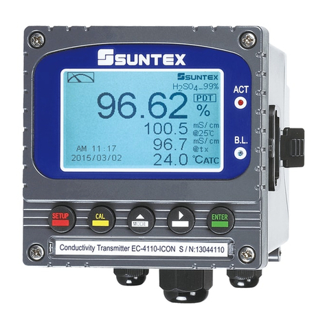
Suntex
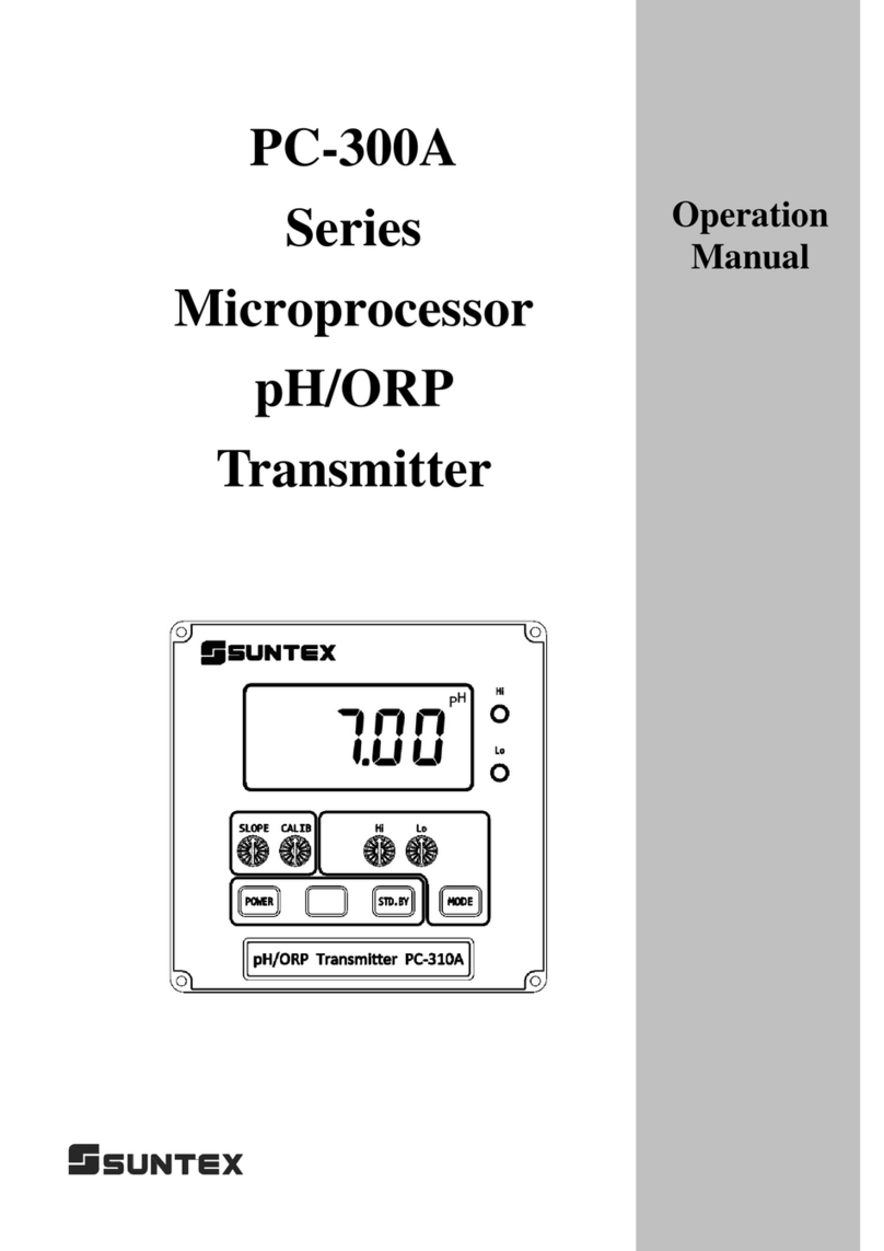
Suntex CT-6110-POL User manual

Suntex
Suntex PC-3110-RS User manual

Suntex
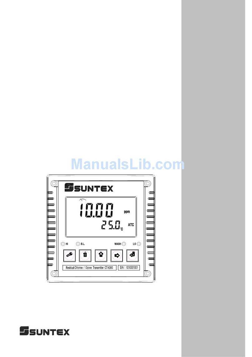
Suntex CT-6300 User manual

Suntex
Suntex EC-4110-I User manual

Suntex
Suntex PC-300A Series User manual

Suntex
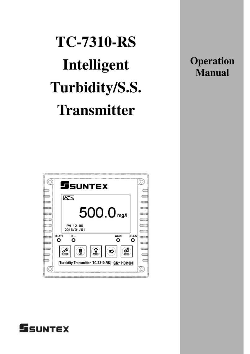
Suntex TC-7310-RS-M User manual

Suntex
Suntex IT-8100 User manual

Suntex
Suntex PC-3310-RS User manual

Suntex
Suntex PC-3110-P User manual
Suntex
Suntex CT-6300RS User manual
Popular Transmitter manuals by other brands

DMP Electronics
DMP Electronics 1101 installation guide

IFM
IFM TAD 81 Series operating instructions

Linear
Linear 1050 installation instructions

DMP Electronics
DMP Electronics 1141 installation guide

K-Mate
K-Mate AT1900-1A-MFI user manual

Camille Bauer
Camille Bauer KINAX N702-INOX HART operating instructions