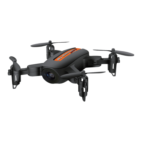
epoc Stryder MK I User manual

Stryder MK I, III & V
User Manual
V3.1 2020-03-15
General information
READ THIS USER MANUAL CAREFULLY BEFORE USING ANY EPOC HARDWARE
Applicable Regulations
Unmanned Aircraft are subject to regulations enforced by civil aviation authorities. Regulations
may vary depending on the country where you intend to operate your product. ANY USE OF
EPOC UNMANNED INC. PRODUCTS IN BREACH OF THE LAW OF THE COUNTRY WHERE
YOU OPERATE THE PRODUCT IS UNDER YOUR SOLE RESPONSIBILITY. INFORM
YOURSELF BEFORE USING THE PRODUCT. CANADA HAS LAWS THAT LIMIT THE USE
OF UNMANNED AIRCRAFT TO LINE-OF-SIGHT OPERATIONS AND/OR PROHIBIT THE
USE OF UNMANNED AIRCRAFT AT ALL OR IN SPECIFIC AREAS/AIRSPACE.
Limitation of Liability
EPOC UNMANNED INC. SHALL NOT BE LIABLE FOR SPECIAL, INDIRECT, INCIDENTAL
OR CONSEQUENTIAL DAMAGES, LOSS OF PROFITS OR PRODUCTION OR
COMMERCIAL LOSS IN ANY WAY, REGARDLESS OF WHETHER SUCH CLAIM IS BASED
IN CONTRACT, WARRANTY, TORT, NEGLIGENCE, STRICT LIABILITY OR ANY OTHER
THEORY OF LIABILITY, EVEN IF EPOC UNMANNED INC. HAS BEEN ADVISED OF SUCH
DAMAGES. Further, in no event shall the liability of EPOC UNMANNED INC. exceed the
individual price of the Product on which liability is asserted. As EPOC UNMANNED INC. has no
control over use, setup, nal assembly, modication or misuse, no liability shall be assumed nor
accepted for any resulting damage or injury. By the act of use, setup or assembly, the user
accepts all resulting liability. If you as the purchaser or the User are not prepared to accept the
liability associated with the use of the product, purchaser is advised to return the product
immediately in new and unused condition to the place of purchase.
Limited Warranty and Service Agreement
1

Epoc MK III has a limited warranty for the first 50 hours of service. After this period the drone is
to be returned for regular service every 50 hours. After the first 50 hours all component and
labour cost of repair or maintenance is at the expense of the purchaser.
EPOC UNMANNED INC. reserves the right to make changes to specifications and product
descriptions contained in this document at any time without notice. Please visit EPOCUAV.COM
or contact [email protected] for the latest revision. Copyright © 2020 EPOC
UNMANNED INC.
Technical Support
If you have questions regarding Epoc hardware or software please use the troubleshooting
section of this document and then contact [email protected] if a resolution is not
found.
Table of Contents
General information 2
Using this manual 6
Product Profile 6
Introduction / general 6
Warnings 8
Package contents 8
Aircraft diagrams 8
Remote controller diagram 11
Modes 11
Charging the transmitter 12
Control sticks 12
Calibrating the transmitter 14
Base station (optional) 20
Setup 20
Operation 20
Manual log download 20
Maintenance 20
Flight 20
Pre-flight 20
Checklist 20
2

Mission planning 23
Flight modes 24
Data links 24
Failsafes 24
Warnings 25
In-flight 25
Normal flight conditions and instrument gauges 25
Emergency procedures 25
Landing procedure 25
Battery depleted in flight 25
Post-flight 26
Checklist 26
Payloads 26
Direct Geo-referencing payload 26
Operation 26
Camera settings 27
Post Processing 27
Software use 27
Step 1: Geotag flight photos using GeoTagr 27
Step 2: Photogrammetric processing (Agisoft Metashape) 28
Step 3: Data reprojection, height adjustment, accuracy validation (Bluemarble
Globalmapper w/ LIDAR module): 39
Battery management 57
Battery lights and indications / maintenance 57
Stryder MK I Battery buttons / LED 58
Power button / LED 58
Stryder MK III Battery buttons / LED 58
Power button / LED 58
Self balancing 59
Warnings and info 61
Maintenance (MK I and MK III airframes) 61
General info 61
Hour meter schedule 62
Troubleshooting 62
Aircraft flight 62
Drone will not arm 62
Drone drifting in Position hold 62
3

Drone takes off again after landing 62
Drone is not taking photos in flight 63
Drone seems to be taking off to an unknown location. 63
Drone circling in position hold 63
Downloading logs 63
Telemetry logs (off laptop) 63
Aircraft logs (off aircraft) 64
Performance and system specifications (MK I and MK III) 65
General 65
Propulsion 65
Performance 66
Takeoff and landing 66
Electrical 66
Environmental 67
Firmware 67
Glossary 67
4

Using this manual
Product Profile
Introduction / general
Stryder drones are professionally designed and built to perform in a demanding and ever
changing industrial market.
For flight controls see “Manual control of drone with transmitter” in this manual.
The Stryder MK III airframe is a quad rotor (4 rotor drone). The Stryder drone is not permitted to
fly any other payloads than the supplied and approved payloads.
Maximum speed ascending and descending rates are pre-programmed and limited by software
on the Stryder drone. Modification of these and any other parameters is strictly prohibited.
Inside all Stryder drones is an industrial flight controller as well as a communication system. All
broadcasting components fall under CSA standards for broadcasting.
Stryder is powered by intelligent flight batteries, these batteries give warning for overheating,
over cooling, over charging and battery levels. The smart batteries also self-discharge when left
too long.
The Stryder MK III airframe is a folding design with fixed landing gear. Ensure care is taken
when folding the arms that no wires are pinched. The cables are protected with mesh such that
they should easily move within the arm when folded.
There is an hour meter installed on all Stryder drones. The customer must return the drone for
regular maintenance performed by a certified technician at a regular 50 hour intervals.
Do not exceed maximum payload capacity. Only use the supplied payloads with recommended
batteries.
Do not go near, or touch, the propellers or motors while they are spinning as this will cause
serious injuries.
Disconnect the battery during transport and at any time when the drone is not in use for safety.
Do not transport the drone with a battery mounted in the tray this includes inside a
vehicle or on foot.
5

The drone should be moved by hand without the battery installed by standing at the rear of the
drone and grasping the rear left boom and front right boom on the MK III or grasping the front
and rear of the MK I drone.
Only use Epoc Unmanned Inc. manufactured or recommended parts.
If you have any questions or concerns do not hesitate to contact your reseller or Epoc
Unmanned inc. directly.
6

Warnings
Never fly over people. Drones are complex mechanical pieces of equipment that can fail. Never
fly or plan a flight directly over people. Never stand directly under a drone while it is flying in any
state including take-off, landing or horizontal flight.
Rotating propellers can cause serious injury and damage. Fly with caution at all times. Respect
specified setbacks during take off and landings of 30 feet at all times.
Safety gloves and CSA approved safety glasses to be worn at all times.
Package contents
The Stryder MK I and MK III drones are supplied with the following as standard
● Drone c/w custom case and foam insert
● CGS case c/w laptop, transmitter, mast, tool set
The Stryder drones come completely assembled and tested. There is no need for any
assembly. Adjusting or tightening propellers / bolts / nuts may cause malfunction in flight. If paint
mark indicates that movement or loosening has occurred contact the reseller immediately.
Inspect the drone for damages during shipping by doing the following:
● Grab each motor assembly and twist from left to right. It should not move.
● Inspect the propellers for cracks, chips, warpage or signs of wear.
● Inspect the propeller hubs (hinge point near the center of the motor) to see if the bolt has
turned. There are paint marks to indicate any movement.
● Inspect the drone for evidence of damage during transport.
7

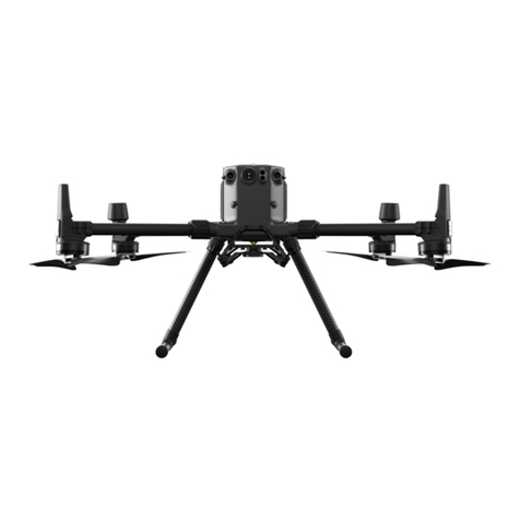
Aircraft diagrams
Stryder MK I
8

Stryder MK III
9

Remote controller diagram
Modes
The Stryder drone transmitter has three modes for flight by default. The modes are controlled by
SF and SC switches as shown above.
GPS = Position hold mode. In this mode the drone will hold its current GPS position and
elevation when the user gives no input to the transmitter sticks. This mode is used to fly
manually. This is done with the SF switch pushed away from the pilot. Confirmation of this can
be seen on the GCS heads up display.
Auto = Autonomous mode. In this mode the drone will perform automated tasks given to it by
apps from the smart device. This is controlled by the SF switch in the position toward the pilot.
This mode should only be selected after a hover test showing that the drone is holding
position correctly and the drone is above 30m.
RTL = Return to Launch. When toggled in the “down position” the drone will return to it’s launch
position and land. This is done with the SC switch. Manual corrections can be made with the
transmitter to adjust where the drone will land.
Timer = The timer automatically starts when the drone is put into Auto mode. This can be reset
by the SH switch.
10

Charging the transmitter
The transmitter is charged via the USB plug in the back of the transmitter or the barrel jack plug
on the bottom depending on model. When the light under the power button on the front of the
transmitter turns off then the transmitter is charged.
Control sticks
Manual control over the drone is carried out with the following inputs to the transmitter. Note that
even in the “Auto” mode inputs to the control sticks will have an effect on the flight of the drone.
Therefore the transmitter should be placed on the hanger while in auto mode such that the
sticks will not be bumped.
It is highly recommended that the transmitter be calibrated on a regular basis in order to correct
for temperature drift in the electronic components. See transmitter calibration section in this
document.
See the following diagrams to explain what happens to the aircraft when the corresponding stick
input is given when in any mode.
Moving the left stick up / down will increase or decrease elevation of Stryder.
11

Moving the left stick to the left / right will rotate the Stryder about its center axis.
Moving the right stick up / down will move the Stryder forward or backward in the direction the
drone is facing.
Moving the right stick left / right will move the Stryder to the left or right of its direction of travel.
12

In order to arm and disarm the drone only the left stick is used.
To arm the drone hold the left stick down and to the right..
To disarm the drone hold the left stick down and to the left until the motors and propellers
stop turning completely.
Calibrating the transmitter
If the drone is “drifting” in Position hold mode then the transmitter may need to be calibrated.
First review the troubleshooting section at the end of this manual to see if transmitter calibration
is needed.
NOTE: Calibration of the transmitter is an advanced operation and done at the user's own
risk. If you do not accept this risk then return the drone to Epoc for calibration.
If transmitter calibration is required follow the following procedure.
There are two calibrations possible and they must be done in this order
1) Horus X10 calibration (you must do with the drone disconnected)
2) Pixhawk (flight control) transmitter calibration
Horus x10 calibration is as follows.
SAFETY WARNING do not power the drone. This procedure is strictly to calibrate the
transmitter within itself.
1. Turn on the transmitter
2. Ensure all trims are centered on the transmitter. Do this by bumping them one way or
another then bumping them back. When centered the radio should speak "trim centre”
13

3. Press and hold the SYS button to get the system menu up
4. Press the Page up/Dn button five times until you see the calibration option
5. Now press the grey button on the right (OK button)
14

6. Press grey button again to start calibration
7. Leave sticks centred
8. Press enter to continue the calibration
9. Move all sticks, sliders, switches to their extreme positions
10. Push OK and you are done.
11. THE TRANSMITTER MUST BE REBOOTED
Pixhawk transmitter calibration is as follows AFTER the transmitter has been calibrated
as per above.
The following are instructions on how to re-calibrate the transmitter on an EPOC drone using a
Horus X10 transmitter
SAFETY WARNING this procedure must be done outside in a clear area because the pilot
may inadvertently arm the drone. This is very unlikely however it is safest to be in a clear space
with the arms unfolded and locked. If the drone arms during this procedure simply move
the stick to the disarm position.
15

1. Plug in the drone battery and turn on the transmitter
2. Ensure all trims are centered on the transmitter. Do this by bumping them one way or
another then bumping them back. When centered the radio should speak "trim centre”
3. Power on the laptop and start up Mission Planner
4. Connect to the drone via mavlink as per usual
5. Click on the "Initial Setup" tab across the top
6. Click on “Manditory Hardware”
7. Click on "Radio Calibration" along the left
16

8. Click on "Calibrate Radio" and say OK (you are outside if the motors arm just disarm
them)
9. It will then ask you to click OK and move all sticks and switches to their extremes. Go
ahead and click OK.
10. Now move the sticks around in a "Circle" but really you are just hitting the four corners of
the stick limits.
11. BE CAREFUL do not hold the left stick in the arming too long or it will arm the
drone. If this happens just give the disarm command and it will shut off.
12. Next move all switches to their full extent.
13. Ensure not to forget the switches on the top of the transmitter.
14. Then click on "Click when done"
15. Centre your sticks and click OK as instructed.
16. WAIT 20 seconds a screen will pop up. Take a photo of this screen and text it to 403
973 0448
17. Numbers should look similar to the ones below. Note that all used channels are from the
high 900's to the low 2000's some vary slightly and that is OK
18. After verifying the numbers click OK
17

19. Go back to the "Flight data" tab on the top
20. Note what mode the drone is in. Cycle through PosHold and Auto modes on the
transmitter. Monitor that each mode shows up correctly.
21. Now flip the RTL switch. No matter what mode you are in RTL will override it and should
say RTL on the screen.
22. When all modes are verified, unplug the drone, turn off the transmitter.
23. Plug in the drone, turn on the transmitter, connect to the PC with the data modem.
24. Verify that all modes are working correctly as per #23 above
18

Base station (optional)
Setup
Operation
Manual log download
Maintenance
All stryder drones have a built in hour meter and must be returned to a qualified service provider
for maintenance every 50 hours. It is the responsibility of the owner to ensure this is completed.
Flight
Pre-flight
Checklist
The following is an example checklist.
The most up to date checklist version can be found on the Epoc website under downloads.
19
Stryder MK III Operations Checklist
RTL Voltage
44.00 V
Flight Date
Pilot
Visual Observer
Client
Site
Airspace Class
VRF/Aircraft Freq.
Aerodrome/Tower Ph.
Nav Canada Emerg Ph.
Loadout
Item
Charged
Packed
Item
Packed
RC
transmitter
SD card
Base Station
USB thumb
drive

20
Camera
batteries
USB cable
Laptop
UAV boom
pliers
Aircraft Radio
UAV
Anemometer
Cellular
phone
UAV
batteries
Phone
charger
Preflight
Start time
Place base station and power on (minimum run time 30 min or 1 hr per km
baseline)
Survey base station location (dimple top center of lid)
Survey minimum 4 check shots (min 24" flat area around check shot)
Place landing mat on level ground
Secure 30m/100' area around landing mat
Place UAV on landing mat and remove foam rotor stays
Unfold UAV booms and hand tighten boom hinges
Tighten boom hinges using boom pliers
Unfold rotors, confirm rotors bolts tight and rotors not damaged
Confirm folding prop adapter paint mark on bolt head unchanged
Confirm motors rotate smoothly and silently
Install USB thumb drive in UAV payload pod
Install SD card in camera
Install battery in camera and power camera on
Format SD card
This manual suits for next models
2
Table of contents
