SAB Heli Division Goblin 700 User manual

REV. 01 Copyright@2011 – SAB Teli division – All rights reserved
Man al Goblin 700
Goblin 700
Goblin 700 Goblin 700
Goblin 700 Manual
ManualManual
Manual

Goblin 700 Manual
Release 1.2 - Febr ary 2012
SAB HELI DIVISION S.R.L.
Via San Crispino, 47
47030 San Ma ro Pascoli (FC) - ITALY

Chapter 1, Introd ction
Copyright@2012 – SAB Heli Division – All rights reserved
Page 1
The Goblin is a high performance radio controlled helicopter.
The design is original, moving away from traditional schemes, searching rationality for simplicity.
O r goal was to create a simple, high performance helicopter, with a minim m of mechanical components, and simple
maintenance.
Please read this ser man al caref lly, it contains instr ctions for the correct assembly of the model.
Please refer to the web site www.goblin-helicopter.com for updates and other important information.
Thank yo for yo r p rchase, and have a great time with yo r Goblin!
SAB Heli Division, 1st Febr ary 2012.
SPEC F CAT ONS
Main rotor diameter: 1568mm (with 690mm blades)
Main blade length: 690 to 710mm
Tail rotor diameter: 296mm
Tail blade length: 115mm
Main shaft diameter: 12mm
Tail shaft diameter: 6mm
Spindle diameter: 10mm
Weight incl ding standard electronics 3290g (excl ding batteries).
Maxim m motor size: 64mm diameter, maxim m height 64mm
Battery compartment: 60x58x350mm (adaptable to 64x58x350mm)
NDEX
1 – Introd ction
2 – mportant notes
3 – Components and Box
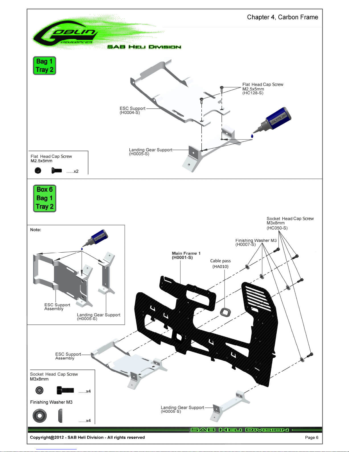
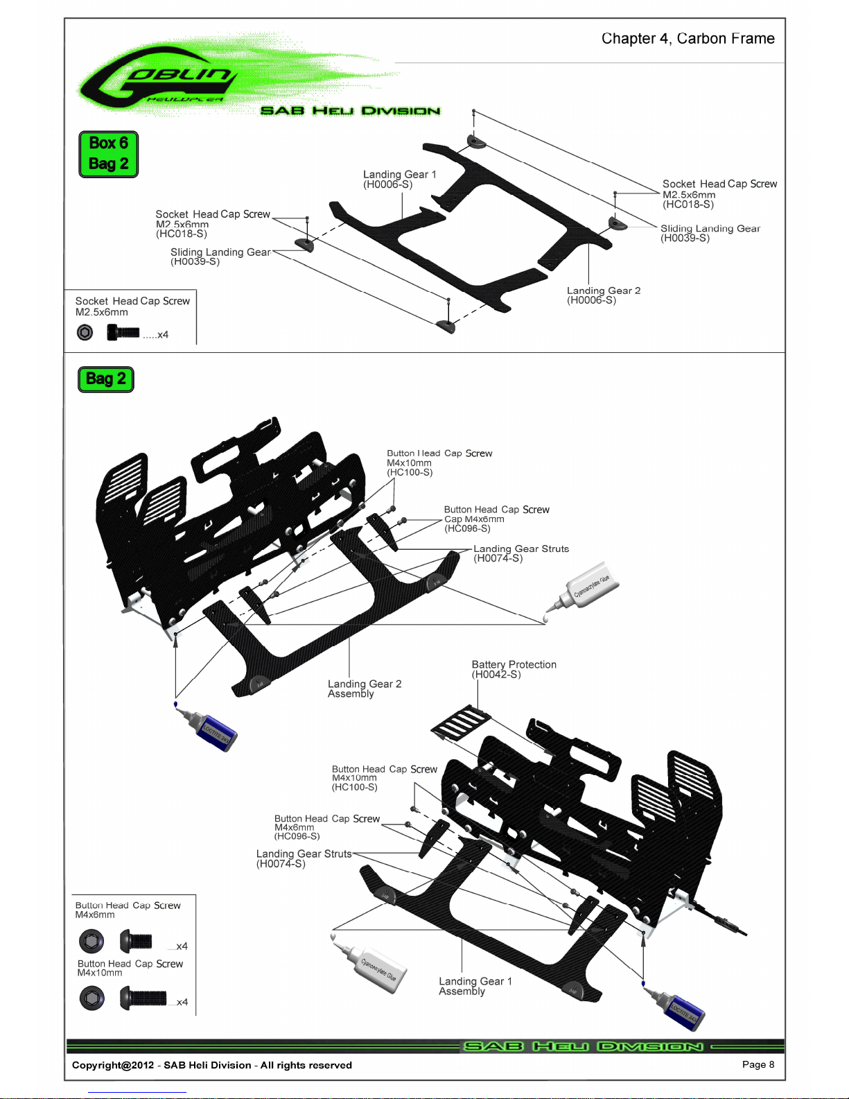
4 – Carbon frame assembly
5 – Trasmission mod le
6 – Main rotor
7 – Tail assembly
8 – Assembling the mod les
9 – Installation of swashplate servos
10 – Installation of the ESC
11 – Installation of Flybarless nit and RX
12 – Installation of the motor
13 – Installation of the boom
14 – Battery and Canopy
15 – n flight
16 – Maintenance
17 – Exploded views
18 – Spare parts
Chapter 2, Important notes
Copyright@2012 – SAB Heli Division – All rights reserved
Page 2
MPORTANT NOTES
•This radio controlled helicopter is not a toy.
•This radio controlled helicopter can be very dangero s.
•This radio controlled helicopter is a technically complex device which has to be b ilt and handled very caref lly.
•This radio controlled helicopter m st be b ilt following these instr ctions. This man al provides the necessary information to
correctly assemble the model. It is necessary to caref lly follow all the instr ctions.
•Inexperienced pilots m st be monitored by expert pilots.
•All operators m st wear safety glasses and take appropriate safety preca tions.
•A radio controlled helicopter m st only be sed in open spaces witho t obstacles, and far eno gh from people to minimize the
possibility of accidents or of inj ry to property or persons.
•A radio controlled helicopter can behave in an nexpected manner, ca sing loss of control of the model, making it very
dangero s.
•Lack of care with assembly or maintenance can res lt in an nreliable and dangero s model.
•Neither SAB Heli Division nor its agents have any control over the assembly, maintenance and use of this product. Therefore,
no responsibility can be traced back to the manufacturer. You hereby agree to release SAB Heli Division from any
responsibility or liability arising from the use of this product.
SAFETY GU DEL NES
•Fly only in areas dedicated to the se of model helicopters.
•Follow all control proced res for the radio freq ency system.
•It is necessary that yo know yo r radio system well. Check all f nctions of the transmitter before every flight.
•The blades of the model rotate at a very high speed; be aware of the danger they pose and the damage they may ca se.
•Never fly in the vicinity of other people.
NOTES FOR ASSEMBLY
Please refer to this man al for assembly instr ctions for this model.
Follow the order of assembly indicated. The instr ctions are divided into chapters, which are str ct red in a way that each step
is based on the work done in the previo s step. Changing the order of assembly may res lt in additional or nnecessary steps.
Use thread lockers and retaining compo nds as indicated. In general, each bolt or screw that engages with a metal part req ires
thread lock.
Factory pre-assembled components have been assembled with all the req ired thread lock and l bricants, and have passed
q ality control. It is not necessary to disassemble and re-assemble them.
It is necessary to pay attention to the symbols listed below:
mportant
Use medi m
thread lock
(eg Loctite 243)
Use retaining
compo nd
(eg Loctite 648)
Use grease
(eg Tri-Flow
Synthetic Grease)
Use CA Gl e
Box xx
Bag xx
Tray xx
Indicates that for this
assembly phase yo need
materials that are in
box xx, bag xx, tray xx.

Chapter 3, Components and Box
Copyright@2012 – SAB Heli Division – All rights reserved
Page 3
ADD T ONAL COMPONENTS REQU RED
•Electric Motor:
10S-12S – 400-600Kv
Maxim m diameter 64mm,
Maxim m height 64mm, pinion shaft diameter 6mm
•Speed controller:
minim m 120A to be safe
•Batteries: 10-12S 4000-5000mAh
•1 flybarless 3 axis control nit
•Radio power system, if not integrated with the ESC.
•3 cyclic servos
•1 tail rotor servo
•6 channel radio control system on 2.4 GHz
(See the config ration example on page 28)
TOOLS, LUBR CANTS, ADHES VES
•Generic pliers
•Hexagonal driver, size 1.5,2,2.5,3,4mm
•4mm T-Wrench
•5.5mm Socket wrench (for M3 n ts)
•8mm Hex fork wrench (for M5 n ts)
•Medi m threadlocker (eg. Loctite 243)
•Strong retaining compo nd (eg. Loctite 648)
•Spray l bricant (eg. Try-Flow Oil)
•Synthetic grease (eg. Tri-Flow Synthetic Grease)
•WD40 L bricant
•Cyanoacrylate adhesive
•Pitch Ga ge (for set- p)
•Soldering eq ipment (for motor wiring)
nside the main box there are:
The assembly process
is described in the following chapters
of this manual.
Each phase begins with a green frame which gives the
box, the bag with screws (and miscellaneous items), and
the foam tray with the components required for the
phase.
nside the main box:
Box 2: Canopy, Blade Holder.
Box 3: Boom, Blades, Tail blades, Carbon rod.
Box 4: Mechanical parts in 4 trays:
Tray 1: Main rotor
Tray 2: Carbon frame and tail rotor
Tray 3: Transmission
Tray 4: Main str ct re
Box 5: Bags
Box 6: Carbon parts
Box 7: Combo Kit (optional)

The man fact ring process of the
carbon parts often leaves micro-b rrs.
We recommend de-b rring the edges
to minimize the risk of electrical wire
c ts, etc
.


Bottom holes: 64mm max height batteries
Top holes: 60mm max height batteries
Other manuals for Goblin 700
1
Table of contents


 user manual")


