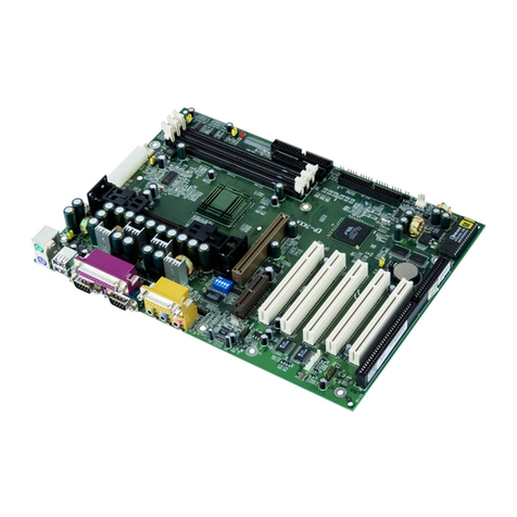
EPOX EP-4PEA User manual

TRADEMARK
All products and company names are trademarks or registered
trademarks of their respective holders.
These specifications are subject to change without notice.
Manual Revision 1.0
September 25, 2002
User’User’
User’User’
User’ss
ss
s
ManualManual
ManualManual
Manual
An Intel SocAn Intel Soc
An Intel Sockk
kk
ket 478 Pret 478 Pr
et 478 Pret 478 Pr
et 478 Processor Basedocessor Based
ocessor Basedocessor Based
ocessor Based
Mainboard (400/533MHz)Mainboard (400/533MHz)
Mainboard (400/533MHz)
SupporSuppor
SupporSuppor
Supportsts
tsts
ts PC1600/PC1600/
PC1600/PC1600/
PC1600/21002100
21002100
2100/2700/2700
/2700/2700
/2700 MemorMemor
MemorMemor
Memory Modulesy Modules
y Modulesy Modules
y Modules
(DDR Memor(DDR Memor
(DDR Memory)y)
y)y)
y)
$ "28

Frequently Asked Questions For POST Port Only
Below is a list of some basic POST Codes possible problems and solutions. For
more detailed information about POST Codes refer to Appendix E in this manual.
POST CODE Probl em Sol uti on
FFh or CFh 1.BIOS chip inserted
incorrectly
2. Incorrect BIOS update
version
3. Mainboard problem
4. dd-on card inserted
incorrectly.
1. Reinsert the BIOS
chip
2. Download the correct
BIOS version update
from the manufacturer's
Web site.
3. Replace mainboard
4. Remove and replace the
add-on card
C1h - C5h 1. Memory module
inserted incorrectly
2. Memory compatibility
problem
3. Memory module
damaged
1. Reinsert memory
module
2. Replace memory
with correct type
3. Replace memory
module
2Dh 1. Error occured in VG
BIOS
2. VG card inserted
incorrectly
1. Replace VG card
2. Reinsert the VG
card
26h Overclock error Clear CMOS or press the insert
key to power on the system
07h - 12h 1. Init keyboard
controller error
2. RTC error
1. Ensure that the keyboard and
mouse are connected
correctly.
2. Replace the RTC battery.

Table of Contents
Section 1 Introduction
Components Checklist.............................................. 1-1
Overview
System Overview ....................................................... 1-2
Chipset Components ................................................. 1-3
Intel Pentium 4 Processors ...................................... 1-4
Accelerated Graphics Port ....................................... 1-6
Utlra ATA66/100 ....................................................... 1-6
Hardware Monitoring................................................ 1-6
IEEE 1394 (Optional) ............................................... 1-7
Serial ATA (Optional)................................................ 1-7
Bandiwdth Overview .................................................. 1-8
Mainboard Form-Factor............................................ 1-9
I/O Shield Connector ................................................ 1-10
Power-On/Off (Remote) .......................................... 1-10
System Block Diagram ............................................. 1-11
Section 2 Features
Mainboard Features ................................................... 2-1
Section 3 Installation
Mainboard Detailed Layout ...................................... 3-2
Easy Installation Procedure
CPU Installation ........................................................ 3-3
Jumper Settings ......................................................... 3-5
System Memory Configuration ................................ 3-6
Device Connectors.................................................... 3-8
External Modem Ring-in Power ON and
Keyboard Power ON Function (KBPO)................... 3-14
Page

STR (Suspend To RAM) Function .......................... 3-15
AGP Card 1.5V protection ....................................... 3-16
Section 4 Award BIOS Setup
Main Menu ................................................................ 4-1
Standard CMOS Setup ............................................... 4-2
Advanced BIOS Features........................................... 4-3
Advanced Chipset Features ....................................... 4- 8
Integrated Peripherals ............................................... 4-11
Power Management Setup ........................................ 4-17
PNP/PCI Configuration Setup .................................. 4-22
PC Health Status........................................................ 4-25
Frequency/Voltage Control ....................................... 4-27
Defaults Menu ........................................................... 4-30
Supervisor/User Password Setting ........................... 4-31
Exit Selecting ............................................................ 4-32
Section 5 Driver Installation
Easy Driver Installation............................................. 5-1
ALC650 Configuration Setup (6 Channel)............... 5-2
Appendi Appendi B
Avance Media Player Users Guide .......................... A-1
Appendi B
Update Your System BIOS ........................................ B-1
Appendi C
EEPROM BOIS Remover ......................................... C-1
Appendi D
GHOST 7 Quick Users Guide (Optional) ............... D-1
Appendi E
POST Codes .............................................................. E-1

Introduction
Page 1-1
Section 1
INTRODUCTION
Package Contents
A
B
USERS
MANUAL
F
H
G
Contents
A. (1) Mainboard
B. (1) Users manual
C. (1) Floppy cable or Floppy round
cable
D. (1) Hard drive cable or Hard drive
round cable
E. (1) Driver and u ili y
Optional Item
F. (1) USB2.0 Cable
G. (1) Game por cable
H. (1) I/O Shield
I. (1) IEEE 1394 2 por cable
J. (1) Blue oo h Module
K. (1) SPD650 card
L. (1) Serial ATA cable
K
J
I
L
CD
or or
E
or

Introduction
Page 1-2
System Overview
This board is designed wi h In el® 845PE chipse . The In el® 845PE chipse
includes MCH(FW82845PE), ICH4(FW82801DB) and FWH hree chips. The
In el® 845PE chipse is designed for In els FC-PGA2 socke 478 package
archi ec ure and suppor he 4X capabili y of he AGP 2.0 In erface Specifica ion.
A new chipse componen in erconnec , he hub in erface, is designed in o he
In el® 845PE chipse o provide more efficien communica ion be ween chipse
componen s.
Suppor of AGP 4X, 266/333MHz DDR SDRAM and he hub in erface provides a
balanced sys em archi ec ure for he Pen ium® 4 in he Socke 478 archi ec ure
processor minimizing bo lenecks and increasing sys em performance. By
increasing memory bandwid h o 2.128GB/s hrough he use of AGP 4X, he
In el® 845PE chipse will deliver he da a hroughpu necessary o ake advan age
of he high performance provided by he powerful Pen ium® 4 in he Socke 478
archi ec ure processor.
The In el® 845PE chipse archi ec ure removes he requiremen for he ISA
expansion bus ha was radi ionally in egra ed in o he I/O subsys em of In el
chipse s. This removes many of he conflic s experienced when ins alling
hardware and drivers in o legacy ISA sys ems. The elimina ion of ISA will provide
rue plug-and play for he In el® 845PE pla form.
In el® 845PE chipse con ains hree core componen s: he Memory Con roller
Hub (MCH), he I/O Con roller Hub (ICH4) and he Firmware Hub (FWH). The
MCH in egra es he da a ransfer ra e of 400/533MHz, Pen ium® 4 processor bus
con roller, AGP 2.0 con roller, 266/333MHz DDR SDRAM con roller and a high-
speed hub in erface for communica ion wi h he ICH4. The ICH4 in egra es an
Ul raATA/66/100 con roller, USB hos con roller, LPC in erface con roller, FWH
in erface con roller, PCI in erface con roller, and a hub in erface for communica-
ion wi h he MCH. The In el® 845PE chipse will provide he da a buffering and
in erface arbi ra ion required o ensure ha sys em in erfaces opera e efficien ly
and provide he sys em bandwid h necessary o ob ain peak performance he
Pen ium® 4 in he Socke 478 archi ec ure.

Introduction
Page 1-3
Chipset Components
The In el® 845PE chipse consis s of he Memory Con roller Hub (MCH), he I/O
Con roller Hub (ICH4) and he Firmware Hub (FWH).
!!
!!
!Memory Controller Hub (MCH)
The MCH provides he in erconnec be ween he DDR SDRAM and he sys em
logic. I in egra es:
- Suppor for single processor wi h a da a ransfer ra e of 400/533MHz.
- 200/266/333MHz DDR SDRAM in erface suppor ing 2GB of DDR SDRAM.
- 4X 1.5V AGP in erface (Only suppor 1.5V on AGP in erface).
- Downs ream hub link for access o he ICH4.
!!
!!
!I/O Controller Hub (ICH4)
The I/O con roller Hub provides he I/O subsys em wi h access o he res of
he sys em. Addi ionally, i in egra es may I/O func ions. The ICH4
in egra es:
- Ups ream hub link for access o he MCH
- 2 Channel Ul ra ATA/33/66/100 Bus Mas er IDE con roller
- USB con roller
- SMBus con roller
- FWH in erface
- LPC in erface
- PCI 2.2 in erface
- In egra ed Sys em Managemen Con roller
- In egra ed LAN Con roller
!!
!!
!Firmware Hub (FWH)
The FWH componen is a key elemen o enabling a new securi y and manage-
abili y infras ruc ure for he PC pla form. The device opera es under he FWH
in erface and pro ocol. The hardware fea ures of his device include a unique a
Random Number Genera or (RNG), regis er-based locking, and hardware-
based locking.

Introduction
Page 1-4
Intel Pentium 4 processors
Formally known as he Willame e, he Pen iumTM 4 is he nex genera ion IA-32
processor from In el. This nex genera ion design is based upon a new micro-
archi ec ure ha brings higher clock speeds and performance han previous
processors could deliver. Among o her advanced fea ures he Pen ium 4 offers
S reaming SIMD ex ensions 2, Advanced Dynamic Execu ion, Hyper Pipelined
Technology, and a da a ransfer ra e of 400/533MHz sys em bus.
Streaming SIMD Extensions
Building upon he founda ions of core fea ures of heir previous line of proces-
sors he Pen ium 4, his new version in roduces S reaming SIMD Ex ensions 2
echnology commonly referred o as SSE2. Bu wha does his mean? SIMD s ands
for Single Ins ruc ion Mul iple Da a. Usually, processors process one da a
elemen in one ins ruc ion, called Single Ins ruc ion Single Da a, or SISD. In
con ras , wi h Single Ins ruc ion Single Da a (SISD), SIMD has he abili y o
process more han one piece of da a elemen during one ins ruc ion.
This echnology is useful for 3D graphics applica ions ha handle considerable
amoun s of floa ing-poin numbers. Wi h SIMD applica ions such as 3D graphics
will be able o processor more da a per ins ruc ion when equa es o be er
performance. This echnology adds 144 new ins ruc ions o he CPU core ha can
be used in a wide varie y of applica ions. Sof ware programmers can for example,
ake advan age of hese new ins ruc ions and wri e more op imized code ha ake
advan age of newer SIMD double-precision floa ing-poin , in eger, and cache
abili y ins ruc ions. In heory his will enable be er nex genera ion services such
as In erac ive Digi al TV o be produced.
Advanced Dynamic Execution
Advanced Dynamic Execu ion describes he improved implemen a ion and
abili ies over he older P6 processor lines ou -of-order decoupled super scalar
execu ion. Dynamic execu ion allows ins ruc ions o he processor o be execu ed
wi hou he need o do so in order. The abili y o do his can add a significan
performance increase versus ordered execu ion.
Introduction
Page 1-5
Hyper Pipelined Technology & 400/533MHz System Bus
Hyper Pipelined Technology doubles he pipeline dep h he Pen ium 4 delivers o
20 s ages. This significan ly increases he performance and frequency capabili ies.
Pen ium 4 also in roduces a 400/533MHz sys em bus as opposed o he 100 and
133MHz bus seen in previous Pen ium III processors. This allows 3.2Gby es per
second of hroughpu while he Pen ium III had a limi ed 1.06Gby e/s hroughpu .
Willame e will repor edly be in roduced in he 0.18-micron using aluminum.
Hyper-Threading Technology
Hyper-Threading Technology is a new fea ures in he IA-32 In el Archi ec ure ha
provides a performance boos for fu ure In el-32 processors based on he In el
Ne Burs TM micro archi ec ure. This echnology enables a single processor o run
wo separa e hreads simul aneously, his arrangemen looks like wo processors.
Hyper-Threading Technology makes a single physical processor appear as mul iple
logical processors, here is one copy of he archi ec ure s a e for each logical
processor, and he logical processor share a single se of physical execu ion
resources. From a sof ware or archi ec ure perspec ive, his means opera ing
sys ems and user programs can schedule processors or hreads o logical proces-
sors as hey would on conven ional physical processors in a mul i-processor
sys em. From a micro archi ec ure perspec ive , his means ha ins ruc ions form
logical processors will persis and execu e simul aneously on shared execu ion
resources.
For more information about all the new features the Pentium 4 delivers check
out the Intel website at http://www.intel.com

Introduction
Page 1-6
Accelerated Graphics Port (AGP or A.G.P.)
Typically, 3D graphics rendering requires a remendous amoun of memory, and
demands ever increasing hroughpu speed as well. As 3D produc s for he
personal compu er become more and more popular, hese demands will only
increase. This will cause a rise in cos s for bo h end users and manufac urers.
Lowering hese cos s as well as improving performance is he primary mo iva ion
behind AGP. By providing a massive increase in he bandwid h available be ween
he video card and he processor, i will assis in relieving some of hese pressures
for qui e some ime.
The board provides he AGP 2.0 in erface. The AGP In erface Specifica ion
revision 2.0 enhances he func ionali y of he original AGP In erface Specifica-
ion (revision 1.0) by allowing 4X da a ransfers (4 da a samples per clock) and
1.5 vol (power supply) opera ion. The AGP 2.0 in erface, along wi h SDRAM
memory echnology, allows graphics con rollers o access main memory a over
1GB/s. In order o ma ch he 4X AGP Card. The board used he Universal AGP
connec or. (1.5 vol AGP Card suppor s only).
Ultra ATA/66/100
The ICH4 provides wo channel Ul ra ATA/66/100 Bus Mas er IDE con rollers, ha
suppor Ul ra ATA/66/100 pro ocols, perfec for such demanding applica ions as
real- ime video, mul imedia, and high performance opera ing sys em. A new IDE
cable is required for Ul ra ATA/66/100. This cable is an 80 conduc or cable;
however he connec ors are, of course, backwards compa ible wi h ATA/33.
Hardware Monitoring
Hardware moni oring allows you o moni or various aspec s of your sys ems
opera ions and s a us. The fea ures include CPU empera ure, vol age and RPM of
fan.

Introduction
Page 1-7
IEEE1394 (Optional)
IEEE 1394 is a high-speed serial bus developed by Apple and Texas Ins rumen s
ha allows users o connec up o 63 devices o he serial bus on a PC. IEEE is
some imes called he IEEE 1394 s andard, he i.Link connec or, FireWire, and he
High Performance Serial Bus (HPSB).
IEEE 1394 provides ransfer ra es up o 400Mbi s/sec. IEEE 1394b provides up o
3200Mbi s/sec ransfer speeds. IEEE 1394 provides enhanced PC connec ivi y
for consumer elec ronics audio/video (A/V) appliances, s orage peripherals,
por able devices such as digi al cameras, and in er-PC communica ions.
IEEE 1394 suppor s ho swapping, mul iple speeds on he same bus, and isochro-
nous da a ransfer providing much needed bandwid h for mul imedia opera ions.
Serial ATA (Optional)
The evolu ionary serial ATA in erface replaces he s andard parallel ATA physical
s orage in erface. The serial ATA specifica ion provides scalabili y and allows
fu ure enhancemen s o he compu ing pla form. Serial echnology overcomes
performance limi s of parallel in erface archi ec ure, mee ing he escala ing need
for fas er da a hroughpu in servers and s orage devices.
Serial ATA is backward compa ible wi h curren sof ware and runs on exis ing
archi ec ure wi hou modifica ion. The serial ATA in erface cable requires lower
vol ages and uses smaller cable connec ors, providing ease of ins alla ion. You can
easily upgrade s orage devices ha are compa ible wi h he serial ATA in erface
specifica ion. Serial ATA suppor s all ATA and ATAPI devices, including high
capaci y removable devices, op ical devices, ape s orage devices, and zip drives.
Serial ATA is comple ely sof ware compa ible wi h parallel ATA, requiring no
modifica ion o your opera ing sys em.

Introduction
Page 1-8
Bandwidth Overview
Table 1 provides a summary of he bandwid h requiremen s for he In el® 845PE
chipse .
Table 1: Intel® 845PE platform Bandwidth Summary
ecafretnI deepSkcolC
)zHM(
rePselpmaS
kcolC
etaRataD
)s/selpmas-ageM(
htdiWataD
)setB(
htdiwdnaB
)s/BM(
suBUPC 331/0014 335/0048 4624/0023
RDD
MARDS 661/331/0012 333/662/0028 4662/8212/0061
0.2PGA 6.664 6624 6601
kniLbuH 6.664 6621662
2.2ICP 3.3313.334 331

Introduction
Page 1-9
Mainboard Form-Factor
The board is designed wi h ATX form fac or - he la es indus ry s andard of
chassis. The ATX form fac or is essen ially a Baby-AT baseboard ro a ed 90
degrees wi hin he chassis enclosure and a new moun ing configura ion for he
power supply. Wi h hese changes he processor is reloca ed away from he
expansion slo s, allowing hem all o hold full leng h add-in cards. ATX defines
a double heigh aper ure o he rear of he chassis which can be used o hos a
wide range of onboard I/O. Only he size and posi ion of his aper ure is
defined, allowing PC manufac urers o add new I/O fea ures (e.g.; TV inpu , TV
ou pu , joys ick, modem, LAN, audio, e c.) o sys ems. This will help sys ems
in egra ors differen ia e heir produc s in he marke place, and be er mee your
needs.
By in egra ing more I/O down on o he board and be er posi ioning he
hard drive and floppy connec ors ma erial cos of cables and add-in cards is
reduced.
By reducing he number of cables and componen s in he sys em, manufac-
uring ime and inven ory holding cos s are reduced and reliabili y will
increase.
By using an op imized power supply, i 's possible o reduce cooling cos s
and lower acous ical noise. An ATX power supply, which has a side-
moun ed fan, allows direc cooling of he processor and add-in cards making
a secondary fan or ac ive hea sink unnecessary in mos sys em applica ions.
Expandable I/O
Figure : Summary of ATX chassis features
CPU
Single chassis fan
for system
Floppy / IDE
connectors
5 /4"
Bay
3 /2"
Bay
AT X
Power
Supply
ATX 2V power
connector
PCI slots
AGP slot
ATX power
connector

Introduction
Page 1-10
I/O Shield Connector
The board is equipped wi h an I/O back panel. Please use he appropria e I/O shield
(figure 3).
Power-On/Off (Remote)
The board has a single 20-pin and 4-pin connec or for ATX or ATX12V power
supplies (Figure 4). For ATX or ATX12V power supplies ha suppor he Remote
On/Off fea ure, his should be connec ed o he mainboard fron panel PW_ON
connec or for he compu er power On/Off bu on.
The board has been designed wi h Sof Off" func ion. You can urn off he sys em
wo ways: pressing he fron panel power On/Off bu on, using he "Sof Off"
func ion (incorpora ed in he mainboards onboard circui con roller) ha can be
con rolled by an opera ing sys em such as Windows®ME/2000/98/95.
Note: For maintaining the DDR SDRAM power during STR (ACPI S3) fun tion, it is
strongly re ommend to use ATX or ATX12V power supplies that have a +5VSB
urrent of (>=) 1A (1000mA). Please he k the 5VSBs spe ifi ation that has been
printed on the ATX or ATX12V power supplys outer ase.
Note: The board requires a minimum of 250 Watt ATX or ATX 12V power supply to
operate. Your system onfiguration (amount of memory, add-in ards, peripherals,
et .) may ex eed the minimum power requirement but to ensure that adequate
power is provided, use a 300 Watt (or greater) ATX or ATX 12V power supply.
J 3
Case (chassis) Power ON/OFF button (J 3)
Figure 4: Simple ATX power ON/OFF controller
12V 4-pin
20-pin
Figure 3: I/O back panel layout
Mic-in
Line-out
Line-in
PS/2 Mouse
PS/2 Keyboard
COM1
Parallel Port RJ-45 LA
(Optional)
USB2.0 ports USB2.0 ports

Introduction
Page 1-11
Figure 5: System Block Diagram
System Block Diagram
MCH
82845PE
(Memory
Controller
Hub)
133/100MHz
66MHz
AGP Bus
4X (1.5V only)
Pentium 4
Processor
478 pin Package
ICH4
(I/O
Controller
Hub)
AC'97
Audio
USB 0,1
AGP Slot
Graphic
Video
Serial Port 1
Serial Port 2
LPT Port
DD
Game
IR
PS/2 Mouse
PS/2 Keyboard
USB 4,5USB 2,3
HDD
(ATA-66/100)
80 Port
PCI Slots
1,-
1,-
LAN
IEEE 1394
(Optional)
Serial ATA
(Optional)
DDR SDRAM
200/266/333MHz
LPC
W83627HF-AW
FWH
(
Firm Ware Hub
)
Flash Memory
(Optional)

Introduction
Page 1-12
Page Left Blank

.A=JKHAI
Page 2-1
Section 2
FEATURES
Mainboard Features
!!
!!
!PROCESSOR
- Socket 478 Intel® Pentium® 4 processor from 1.4 to 2.8GHz
- Supports Hyper-Thre ding Technology
En bling the function lity of Hyper-Thre ding Technology for your
computer system requires ALL of the following pl tform Components:
"CPU: An Intel® Pentium® 4 Processor with HT Technology.
"Chipset: An Intel® Chipset th t supports HT Technology.
"BIOS: A BIOS th t supports HT Technology nd h s it en bled.
"OS: An oper ting system th t supports HT Technology.
!!
!!
!CHIPSET
- Intel 82845PE Chipset (82845PE + ICH4)
!!
!!
!FRONT SIDE BUS
- 400/533MHz
!!
!!
!DRAM MODULE
- 184-pin DDR DIMM x 3 for PC2100/2700 (DIMM2 nd DIMM3 sh red
t the s me b nk)
- DRAM Size: 64MB to 2GB
!!
!!
!EXPANSION SLOT
- 32-bit PCI x 5
-4: AGP x 1 (1.5V only)

.A=JKHAI
Page 2-2
!!
!!
!ONBOARD I/O
- Winbond W83627HF LPC I/O integr ted with keybo rd nd mouse, FDD,
f st IR, power on function, nd p r llel, seri l, nd g me ports
!!
!!
!ONBOARD PCI / IDE
Intel 82801DB/ICH4 controller
- PCI Rev. 2.2 compli nt
- ACPI-compli nt power m n gement
- PCI Bus IDE Port with PIO/Ultr DMA-66/100 x 2 (up to 4 devices)
- Extr IDE Port by HPT372 with Ultr DMA-66/100/133 nd IDE RAID x
2 (up to 4 devices) (Optional)
!!
!!
!Onboard LAN Optional)
- Integr te 10/100Mb f st Ethernet controller in Re ltek RTL8100B L n
chipset by RJ-45 connector
!!
!!
!I/O CONNECTOR
- PS/2 mouse nd keybo rd
- COM1, LPT (printer)
- Line-in/out, MIC
- COM2 nd G me port by extr c ble
- USB connector x 6 (two option l vi m inbo rd front p nel USB
connector). USB supports USB 2.0 specific tion. The USB3 c n support
bluetooth module.
- RJ-45 j ck
!!
!!
!IEEE 1394 Optional)
- Integr ted OHCI 1.1 1394 controller
- Supports two 400Mbps 1394 ports
!!
!!
!Serial ATA Optional)
- Repl ces the p r llel ATA interf ce, providing gre ter throughput.
- Supports current oper ting systems nd softw re.

.A=JKHAI
Page 2-3
- Supports ll ATA nd ATAPI devices, including high c p city remov ble
devices, optic l devices, t pe stor ge devices, nd zip drives.
!!
!!
!BIOS
- Aw rd Plug & Pl y BIOS
!!
!!
!Built-in AC 97 Digital Audio by Realtek ALC650 6 channel)
- Compli nt with AC97 2.2 specific tion
- Six-ch nnel, slot select ble DAC (Digit l An log Converter) output for
multi-ch nnel pplic tions
- Supports digit l SPDIF function
- Supports g me nd MIDI port
!!
!!
!EXTENDED FUNCTION
- Supports H rdw re Monitoring function by W83627HF-AW
- Supports exclusive KBPO (Keybo rd Power On) function
- Supports W ke-On-LAN function
- Supports STR (Suspend To RAM) power s ving function
- Supports CPU clock nd r tio settings vi BIOS
- Supports CPU Vcore, memory nd AGP volt ge settings vi BIOS
- Supports M gic He lth nd E sy Boot Function
- Supports Asynchronous Tr nsfer Mode between PCI & FSB
- Supports Progr mm ble AGP/PCI clock output frequency with 1MHz
increment
- Supports AGP 1.5V Protection
- 80 Port onbo rd design with 7-segment LED displ y (Option l)
!!
!!
!FORM FACTOR
- 305 mm x 245 mm ATX size

.A=JKHAI
Page 2-4
Page Left Blank
Table of contents
Other EPOX Motherboard manuals
Popular Motherboard manuals by other brands

Gigabyte
Gigabyte B365M GAMING HD user manual

AOpen
AOpen MK7A Easy installation guide

Teknor Industrial Computers
Teknor Industrial Computers VIPer807 Technical reference manual

IEI Technology
IEI Technology IMBA-G410 Quick installation guide

EVGA
EVGA 132-LF-E655-KR Visual guide

Foxconn
Foxconn P45A Series user manual