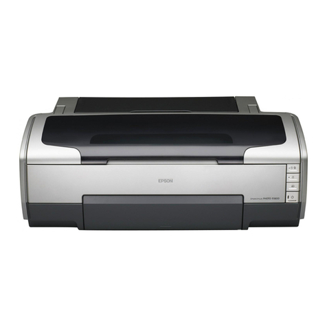
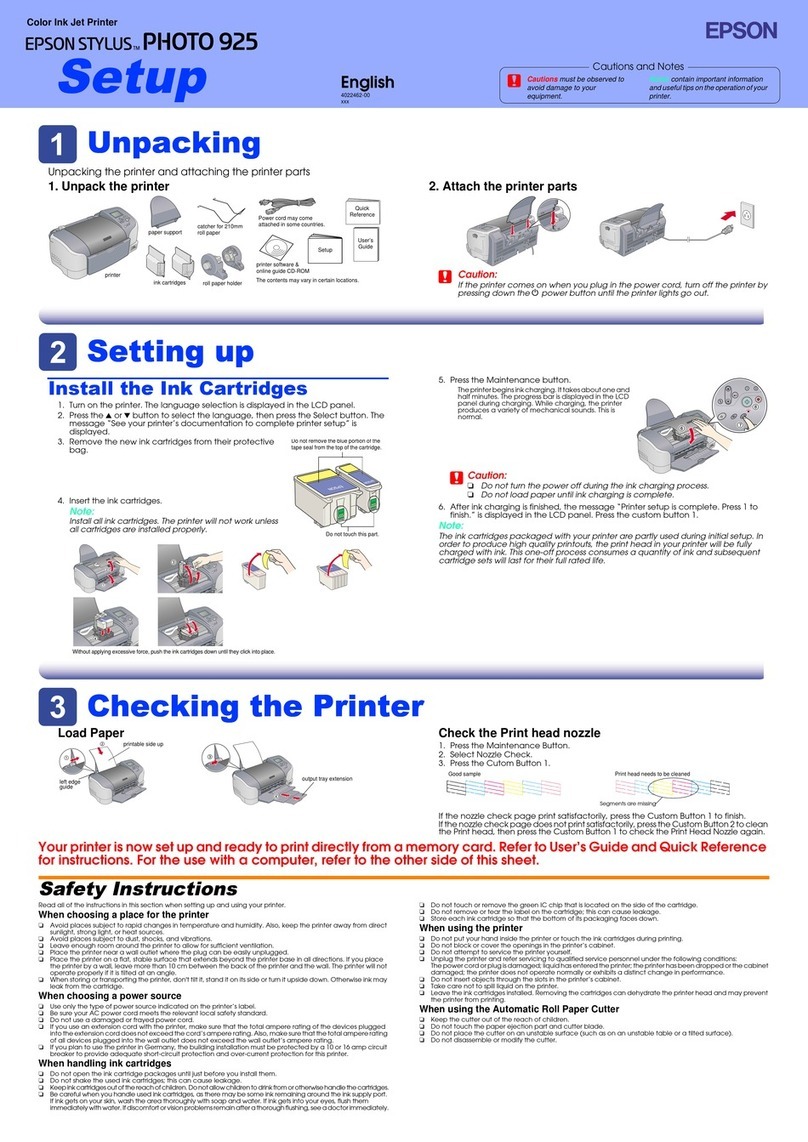
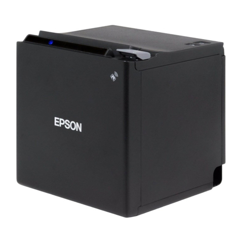
1.1 FEATURES
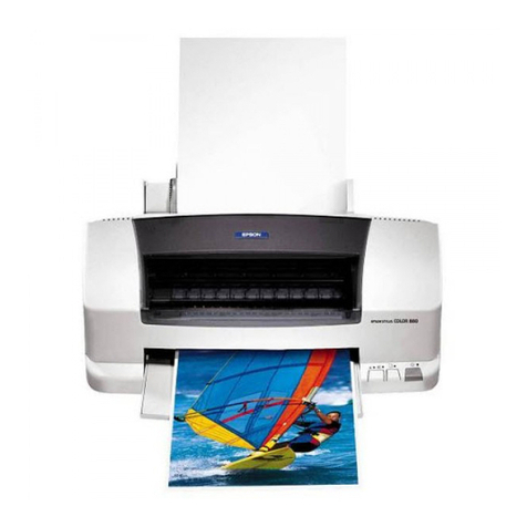
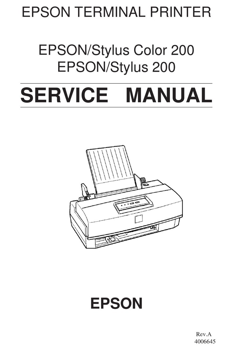
EPSON Stylus Color 660/660
are designed for PC users at home
and low price for hat high performance. Also, Stylus Color 440 printer
has the same high color print quality (720 X 720dpi) as Stylus ProXL,
and
Stylus Color 640,740,660
have the same high color print
quality (1440 X 720) as Stylus Color 600 and Stylus Pro 5000. The
major printer features are;
o
High color print quality
n
720 (H) x 720 (V) dpi printing (for Stylus Color 440)
n
1440 (H) X 720 (V) dpi printing (for Stylus Color 640, 660, 740)
n
4 color printing (YMCK)
n
Traditional and New Microwave
n
Black 64 nozzles, CMY 21 nozzles (for Stylus Color 440)
n
Black 64 nozzles, CMY 32/color nozzles (for Stylus Color 640,
660)
n
Black 144 nozzles, CMY 48/color nozzles (for Stylus Color 740)
o
Built-in auto sheet feeder
n
Holds 100 cut-sheets (64g/m2)
n
Holds 10 envelopes
n
Holds 30 transparency films
n
Holds 65 special papers
o
High-speed print
n
200 cps (for Stylus Color 440, 740)
n
Normal 200 cps, Draft 400 cps (only for Stylus Color 640, 660)
n
By using head drive frequency 14.4KHz, printing speed is twice
faster than Stylus Color.
o
Compact size
n
429mm (W) x 231mm (D) x 155mm (H) (for Stylus Color 440)
n
429mm (W) x 231mm (D) x 157mm (H) (for Stylus Color 640,
660)
n
429mm (W) x 261mm (D) x 157mm (H) (for Stylus Color 740)
n
Weight: 5.2Kg (for 3 models)
o
Acoustic noise
n
Approximately 45 dB (for Stylus Color 440)
n
Approximately 47 dB (for Stylus Color 640, 660, 740)
o
Interface
n
Bi-directional parallel I/F IEEE-1284 level 1 device (for 3
models)
n
Mac serial I/F up to approx. 1800 kbps (only for Stylus Color
740)
n
USB (only for Stylus Color 740)
o
One unit combined black and CMY head
o
Windows exclusive (for Stylus Color 440, 640, 660)
o
Standard, NLSP, 5 Scaleable fonts (only for Stylus Color 740)
o
Stylus Color 660 is the reflesh version based on Stylus
Color 640. The differen e points are as follows;
n
Following EEPROM Datas
Address Data
*02H: 03H
*72H: 36H
*73H: 36H
*74H: 30H
