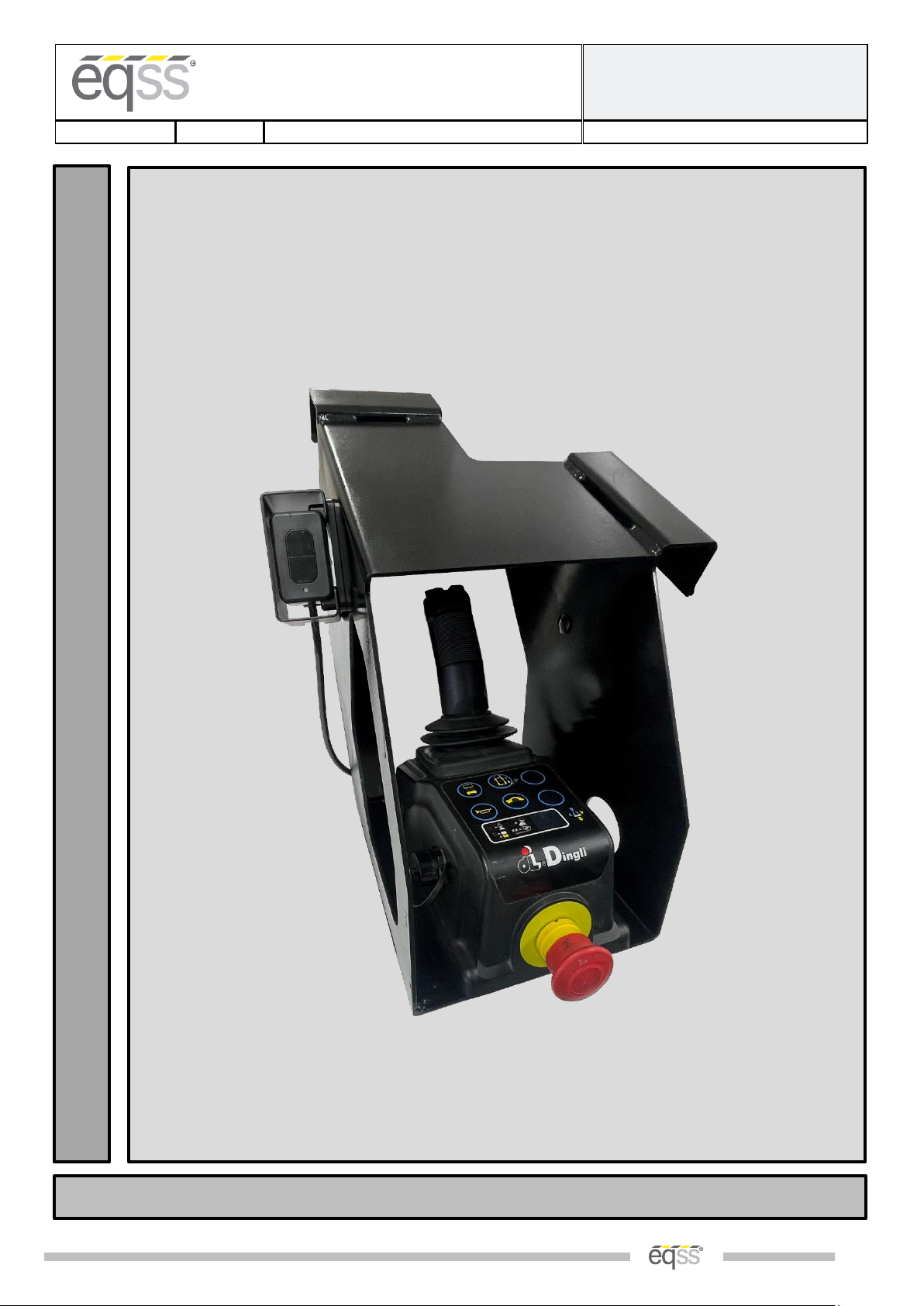
eqss OverWatch Dingli ACE Series User manual

EQUIPMENT SAFETY SYSTEMS
75 Naxos Way, Keysborough 3173 Victoria Australia
P: +61 3 8770 6555 E: support@eqss.com.au
Dingli ACE Series
Installation Manual
REV 1.1
14/09/2022
Model6253 OverWatch™Installation Manual
Document # DO001488
EQSS Model6253 –OverWatch™
Dingli ACE Series
I
N
S
T
A
L
L
M
A
N
U
A
L
** Failure to follow this installation manual will void warranty **

EQUIPMENT SAFETY SYSTEMS
75 Naxos Way, Keysborough 3173 Victoria Australia
P: +61 3 8770 6555 E: support@eqss.com.au
Dingli ACE Series
Installation Manual
REV1.1
14/09/2022
Model6253 OverWatch™Installation Manual
Document # DO001488
|2 of 21|
AUTHORS:
Kieren Grogan
AUTHORISED BY:
Kieren Grogan
CHECKED BY:
Kieren Grogan
DOCUMENT ABSTRACT:
This Installation Manual details the manufacturer’s installation instructions for installing the Model6253 OverWatch™ on a
Dingli ACE series scissor lift.
PRODUCT NAME:
Model6253 OverWatch™ Operator Detection System
REFERENCE DOCUMENTS:
DO0001195 Model6253 OverWatch™ User Manual
CURRENT DOCUMENT REVISION:
1.1
REVISION INFORMATION:
•1.0 Initial Document Creation for installation on a Dingli ACE series machine
•1.1 Updated images and wire harness schematics

EQUIPMENT SAFETY SYSTEMS
75 Naxos Way, Keysborough 3173 Victoria Australia
P: +61 3 8770 6555 E: support@eqss.com.au
Dingli ACE Series
Installation Manual
REV1.1
14/09/2022
Model6253 OverWatch™Installation Manual
Document # DO001488
|3 of 21|
Important Information
Information contained in this publication regarding this device’s applications and the like, is provided only for your
convenience and may be superseded by updates. It is your responsibility to ensure that the application or our
equipment meets with your specifications.
EQUIPMENT SAFETY SYSTEMS MAKE NO REPRESENTATIONS OR WARRANTIES OF ANY KIND, WHETHER EXPRESSED OR
IMPLIED, WRITTEN OR ORAL, STATUTORY OR OTHERWISE, RELATED TO THE INFORMATION, INCLUDING, BUT NOT
LIMITED TO, IT’S CONDITION, QUALITY, PERFORMANCE, MERCHANTABILITY OR FITNESS FOR PURPOSE.
Equipment Safety Systems disclaims all liability arising from this information and its use. Use of Equipment Safety
Systems’ products as critical components in life support systems is not authorised except with express written
approval by Equipment Safety Systems. No licenses are conveyed, implicitly or otherwise, under any Equipment Safety
Systems intellectual property rights.
This is a class A product certified to AS/NZS CISPR 22:2006. In a domestic environment this product may
cause radio interference in which case the user may be required to take adequate measures.

EQUIPMENT SAFETY SYSTEMS
75 Naxos Way, Keysborough 3173 Victoria Australia
P: +61 3 8770 6555 E: support@eqss.com.au
Dingli ACE Series
Installation Manual
REV1.1
14/09/2022
Model6253 OverWatch™Installation Manual
Document # DO001488
|4 of 21|
Table of Contents
Preparation.........................................................................................................................................................................5
Required Tools ...............................................................................................................................................................5
Installation Time ............................................................................................................................................................ 5
Installation Instructions......................................................................................................................................................6
Operator Sensor.............................................................................................................................................................6
Control Module..............................................................................................................................................................8
Post Installation Configuration .........................................................................................................................................13
Overview...................................................................................................................................................................... 13
Minimum system requirements ..................................................................................................................................13
Wi-Fi Connection & Web Page Access .........................................................................................................................13
Machine Model Selection ............................................................................................................................................14
Installation Test............................................................................................................................................................ 15
Change Model Configuration.......................................................................................................................................16
Set Date and Time........................................................................................................................................................ 17
System Settings.................................................................................................................................................................18
Polarity and Input Style................................................................................................................................................ 20
AS002208 Plug and Play Harness Drawing .......................................................................................................................21

EQUIPMENT SAFETY SYSTEMS
75 Naxos Way, Keysborough 3173 Victoria Australia
P: +61 3 8770 6555 E: support@eqss.com.au
Dingli ACE Series
Installation Manual
REV1.1
14/09/2022
Model6253 OverWatch™Installation Manual
Document # DO001488
|5 of 21|
Preparation
Required Tools
The OverWatch™ has been designed to be fitted using basic workshop tools. Shown below is a list of tools required
to complete the installation
Item
Tool / Description
1
Electric Drill
2
Centre punch
3
Hammer
4
Side Cutters
5
Drill 3.2mm
6
Drill 5.0mm
7
Step Drill –up to 20mm
8
Metric sockets or spanners
9
Needle nose pliers
10
Screw drivers
Installation Time
The suggested time required to install the OverWatch™ is as detailed below
Task
Estimated Time (Minutes)
Drilling of all mounting holes for the various components
10
Mechanical assembly
10
Electrical assembly
15
Post installation system tests
10
Total
45

EQUIPMENT SAFETY SYSTEMS
75 Naxos Way, Keysborough 3173 Victoria Australia
P: +61 3 8770 6555 E: support@eqss.com.au
Dingli ACE Series
Installation Manual
REV1.1
14/09/2022
Model6253 OverWatch™Installation Manual
Document # DO001488
|6 of 21|
Installation Instructions
Operator Sensor
Step
Description
Diagram
1.
Remove the Joystick
controller from the metal
housing.
2.
Drill the holes to mount the
operator sensor on the
outside of the metal housing
The position of the operator
sensor is critical, the angle of
the sensor must be at an
angle of 45 degrees, and it
must be mounted exactly as
per the corresponding
drawing.

EQUIPMENT SAFETY SYSTEMS
75 Naxos Way, Keysborough 3173 Victoria Australia
P: +61 3 8770 6555 E: support@eqss.com.au
Dingli ACE Series
Installation Manual
REV1.1
14/09/2022
Model6253 OverWatch™Installation Manual
Document # DO001488
|7 of 21|
3.
Mount the operator sensor in
the position using the
supplied positioning wedges,
sensor guard, M4 washers,
nuts and bolts.
The orientation of the wedge
blocks is critical for the
correct positioning of the
operator sensor, make sure
that the sensor is angled,
such that it is twisted
outwards from the joystick
controller.
4.
Route the operator sensor
cable as shown in the
diagram. Using the supplied
P-Clip to secure the cable to
the metal box.

EQUIPMENT SAFETY SYSTEMS
75 Naxos Way, Keysborough 3173 Victoria Australia
P: +61 3 8770 6555 E: support@eqss.com.au
Dingli ACE Series
Installation Manual
REV1.1
14/09/2022
Model6253 OverWatch™Installation Manual
Document # DO001488
|8 of 21|
Control Module
Step
Description
Diagram
1.
Remove the bottom
plastic cover from the
Joystick to expose the
inside wiring and
electronics.
2.
Remove the Buzzer, E-
Stop, and the controller
circuit board from the
plastic enclosure.
3.
Drill a 20mm hole to run
the operator sensor M20
Gland into the plastic
joystick enclosure. The
position of the hole is
detailed as in the image. It
is recommended to use a
step drill for this hole, as it
is running through plastic
material.

EQUIPMENT SAFETY SYSTEMS
75 Naxos Way, Keysborough 3173 Victoria Australia
P: +61 3 8770 6555 E: support@eqss.com.au
Dingli ACE Series
Installation Manual
REV1.1
14/09/2022
Model6253 OverWatch™Installation Manual
Document # DO001488
|9 of 21|
4.
Use a fine metal pick to
clean the area shown in
the red circles on the
adjacent image to allow
access to the pins. This
process removes the
conformal coating on the
PCB and allows electrical
access to the drive,
elevate and horn
connections on the circuit
board.
5.
Use a fine pair of side
cutters to trim down the
signal pins. These
connections must be
trimmed to be as flat as
possible so that the spring
pin from the plug and play
board can make suitable
contact with the terminal
6.
Trim down the Elevate
signal pin. This pin is
located as displayed in the
image. Using a fine pair of
side cutters make sure
that the pin is trimmed
flat.

EQUIPMENT SAFETY SYSTEMS
75 Naxos Way, Keysborough 3173 Victoria Australia
P: +61 3 8770 6555 E: support@eqss.com.au
Dingli ACE Series
Installation Manual
REV1.1
14/09/2022
Model6253 OverWatch™Installation Manual
Document # DO001488
|10 of 21|
7.0
Trim down the Drive
signal pin. This pin is
located as displayed in the
adjacent image. Using a
fine pair of side cutters
make sure that the pin is
trimmed flat.
8.0
Trim down the two Horn
signal pins. These pins are
located as displayed in the
adjacent image. Using a
fine pair of side cutters
make sure that the pins
are trimmed flat.
9.0
Locate the AS002208 Plug
and play loom from the
OverWatch Kit. This
assembly consists of a
wire harness and a small
circuit board with gold
plated spring pins. The
circuit board sits on top,
of the joystick circuit
board and the signal
connections are made by
the spring-loaded gold
pins.

EQUIPMENT SAFETY SYSTEMS
75 Naxos Way, Keysborough 3173 Victoria Australia
P: +61 3 8770 6555 E: support@eqss.com.au
Dingli ACE Series
Installation Manual
REV1.1
14/09/2022
Model6253 OverWatch™Installation Manual
Document # DO001488
|11 of 21|
10
Mount the Overwatch
circuit board on top of
joystick circuit board.
Using the provided screws
and spacers in the kit.
Make sure that the board
is sitting in the correct
position and the spring
pins are contacting the
joystick circuit board
signal pins.
11
Install the Overwatch
joystick connectors in
between the joystick and
the control box circuit
board.
Visually check that all pins
from the original joystick
connector have a
corresponding cable on
the Overwatch harness.
Reconnect the other
connectors, which were
disconnected in step 1 to
the control box circuit
board.
12.
At the back of the Estop,
install the OverWatch Red
Power cable to terminal 1
of the E-Stop.
Note: this cable might
need to be changed to
terminal 2 if the
Overwatch is powered
with the E-stop pushed in.

EQUIPMENT SAFETY SYSTEMS
75 Naxos Way, Keysborough 3173 Victoria Australia
P: +61 3 8770 6555 E: support@eqss.com.au
Dingli ACE Series
Installation Manual
REV1.1
14/09/2022
Model6253 OverWatch™Installation Manual
Document # DO001488
|12 of 21|
13
Mount the OverWatch
ECU inside the joystick
control box, the ECU is
mounted to the metal
joystick gimble using the
adhesive Velcro tape.
Run the operator sensor
cable through the
predrilled 20mm hole and
secure the cable gland.
Connect the 8-pin
connector from the
operator sensor and the
12-pin connector from the
overwatch loom to the
ECU.
14.
Re-assemble the joystick
control box and mount to
the metal shroud.
Make sure the operator
sensor cable runs clear to
the joystick enclosure and
tighten the M20 gland to
seal the cable entry point.

EQUIPMENT SAFETY SYSTEMS
75 Naxos Way, Keysborough 3173 Victoria Australia
P: +61 3 8770 6555 E: support@eqss.com.au
Dingli ACE Series
Installation Manual
REV1.1
14/09/2022
Model6253 OverWatch™Installation Manual
Document # DO001488
|13 of 21|
Post Installation Configuration
Overview
After the OverWatch™ has been installed it must be configured with the parameters to suit the machine. Follow
the instructions below to configure the OverWatch™.
Minimum system requirements
Any smart phone, tablet or laptop that meets the following requirements:
•The device can connect to a Wi-Fi access point
•The device has an up to date web browser installed (2019 onwards). Firefox or Chrome are
recommended.
Wi-Fi Connection & Web Page Access
To enable the Wi-Fi connection on the OverWatch™ to complete the configuration follow the steps below.
1. Power down the platform control box with the ESTOP
2. Wait 10 seconds
3. Power up the platform control box with the ESTOP
4. While standing in the operator position, switch on the OverWatch™
5. As the welcome chime starts to play, cover the sensor. The LED will flash white then black to acknowledge.
6. Remove your hand from the sensor. The LED will flash white then black to acknowledge.
7. After covering then uncovering the sensor this way 2 more times, "Wi-Fi On" will be announced.
8. On your Wi-Fi enabled device (laptop, tablet, smartphone, etc), show the available wireless networks
9. Select the wireless network (starts with “overwatch”) to connect to the OverWatch™
10. When prompted, enter the password “12345678”
11. Open your preferred web browser (Chrome, Firefox, Safari, Edge)
12. Enter the following into the address bar http://192.168.4.1 to open the OverWatch™main page

EQUIPMENT SAFETY SYSTEMS
75 Naxos Way, Keysborough 3173 Victoria Australia
P: +61 3 8770 6555 E: support@eqss.com.au
Dingli ACE Series
Installation Manual
REV1.1
14/09/2022
Model6253 OverWatch™Installation Manual
Document # DO001488
|14 of 21|
Machine Model Selection
Follow the instructions below to configure the OverWatch™.
1. Select the Setup option
2. If there is a password field at the bottom of the page, follow the instructions in Change Model Configuration
to obtain the password and enter the password field
3. Select the EWP Model from the drop-down list and click Set
4. Click on Proceed to Test to begin the installation test

EQUIPMENT SAFETY SYSTEMS
75 Naxos Way, Keysborough 3173 Victoria Australia
P: +61 3 8770 6555 E: support@eqss.com.au
Dingli ACE Series
Installation Manual
REV1.1
14/09/2022
Model6253 OverWatch™Installation Manual
Document # DO001488
|15 of 21|
Installation Test
After the model configuration has been set or updated an Installation Test must be performed. This will ensure the
installation has been correctly performed and the OverWatch™is functioning correctly.
Follow the instructions on the web page to complete the Installation Test.

EQUIPMENT SAFETY SYSTEMS
75 Naxos Way, Keysborough 3173 Victoria Australia
P: +61 3 8770 6555 E: support@eqss.com.au
Dingli ACE Series
Installation Manual
REV1.1
14/09/2022
Model6253 OverWatch™Installation Manual
Document # DO001488
|16 of 21|
Change Model Configuration
To reconfigure the OverWatch™for a different model requires an authorisation password to be supplied by a
service manager. The authorisation password is generated from the EQSS website. The EQSS website requires a
login username and password. If you are a service manager and don’t have a username and password, contact
EQSS to register. Follow the instructions below to obtain an authorisation password.
1. Open your preferred web and enter the following into the address bar http://www.eqss.com.au/overwatch
to open the Login page
2. Select Customer
3. Enter your username and password
4. Ask the service technician for the serial number shown on the Setup page or on the ECU module along with
the owner details of the EWP and complete the details form then click Generate Hash
5. Provide the 5-digit hash password to the service technician

EQUIPMENT SAFETY SYSTEMS
75 Naxos Way, Keysborough 3173 Victoria Australia
P: +61 3 8770 6555 E: support@eqss.com.au
Dingli ACE Series
Installation Manual
REV1.1
14/09/2022
Model6253 OverWatch™Installation Manual
Document # DO001488
|17 of 21|
Set Date and Time
Date and time should be set accordingly. The date and time can be set on the log page. This page allows
adjustment of the system’s real time clock and calendar if required. Please note, any time or date change is logged
and recorded.

EQUIPMENT SAFETY SYSTEMS
75 Naxos Way, Keysborough 3173 Victoria Australia
P: +61 3 8770 6555 E: support@eqss.com.au
Dingli ACE Series
Installation Manual
REV1.1
14/09/2022
Model6253 OverWatch™Installation Manual
Document # DO001488
|18 of 21|
System Settings
See the sections below for details on each of the Dingli ACE Series OverWatch™system default settings.
Setting Name
Description
Value
deltaseek
This specifies which of the previous lidar reading to
compare against the current one to calculate the
speed.
20
max_safe_velocity
This is the velocity threshold for the cutout in cm/s.
for drive mode.
95
max_safe_displacement
This is the maximum permitted distance in cm the
operator may be away from the calibration position in
drive mode.
50
max_safe_velocity_elevate
This is the velocity threshold for the cutout in cm/s. in
elevate mode.
75
max_safe_displacement_elevate
This is the maximum permitted distance in cm the
operator may be away from the calibration position in
elevate mode.
50
max_safe_velocity_neutral
This is the velocity threshold for the cutout in cm/s. in
neutral mode.
60
max_safe_displacement_neutral
This is the maximum permitted distance in cm the
operator may be away from the calibration position in
neutral mode.
40
fwddispadj
The coefficient to apply to the displacement when the
displacement is toward the sensor.
-0.8
fwdveloadj
The coefficient to apply to the velocity when the
displacement is toward the sensor.
-1
zone_obstruction
The lidar is considered obstructed if the lidar sensor
reading is below this.
5
zone_minimum
Any lidar reading below this will trigger a cutout with
the message: “Operator Zone”
15
zone_maximum
Any lidar reading above this will trigger a cutout with
the message: “Operator Zone”
120
horn_count_max
The number of times the horn will sound when
alerting the operator if the trigger remains pressed
during the cutout.
2
horn_time_ms
The amount of time in milliseconds each individual
horn should play.
200
adc_elevate_threshold
For the elevate ADC input, a reading below this
indicates the EWP is in elevate mode.
500
adc_drive_threshold
For the drive ADC input, a reading below this indicates
the EWP is in drive mode.
500
adc_trigger_threshold
For the trigger ADC input, a reading below this
indicates the trigger is pressed.
100

EQUIPMENT SAFETY SYSTEMS
75 Naxos Way, Keysborough 3173 Victoria Australia
P: +61 3 8770 6555 E: support@eqss.com.au
Dingli ACE Series
Installation Manual
REV1.1
14/09/2022
Model6253 OverWatch™Installation Manual
Document # DO001488
|19 of 21|
Setting Name
Description
Value
adc_joystick_fwd_threshold
For the joystick ADC input, a reading below this
indicates the joystick has been pushed forward.
900
adc_joystick_bwd_threshold
For the joystick ADC input, a reading above this
indicates the joystick has been pulled backward.
1100
override_cooldown
The amount of time in milliseconds the system will
wait before accepting another override request.
20000
override_time
The amount of time in milliseconds the override will
last before it expires, and normal operation is
resumed.
15000
override_listening_time
The amount of time in milliseconds the system will
wait while the deadman is held down before
considering it not to be part of the triple click override
request.
300
override_reset_time
The amount of time in milliseconds the override
system will wait before resuming listening after the
deadman has been released at the end of an override
period.
500
override_triple_click_time
The amount of time in milliseconds 3 clicks of the
deadman need to occur to trigger the override.
2000
lidar_fault_timeout
The amount of time in milliseconds of silence from the
sensor module before a fault condition is triggered.
1000
cutout_fault_timeout
The amount of time in milliseconds a discrepancy
between the cutout and the cutout sensor is
permitted before a fault condition is triggered.
3000
throttle_time
Period after the trigger is pressed, the system does
not track velocity.
2000
time_before_welcome
Time after power on before welcome audio is played
250
stuck_displacement
While the operator is within this distance in cm of the
position they were in when the cutout occurred, the
operator is considered trapped.
20
stuck_time
The period in milliseconds the operator needs to
remain still after a cutout to be considered trapped.
5000
stuck_time_long
After the stuck time this is the interval between horn
alerts.
10000
wifi_on_click_count
The number of times the trigger needs to be pressed
after start-up to enter Wi-Fi mode.
10
wifi_on_click_time
The timeout after start-up before OverWatch stops
listening to the trigger click method of turning on the
Wi-Fi
10000
wifi_on_gesture_count
The number of times to cover and uncover the sensor
to enter Wi-Fi mode.
3
wifi_on_gesture_time
The timeout before OverWatch stops waiting for the
next part of the gesture in milliseconds
3000

EQUIPMENT SAFETY SYSTEMS
75 Naxos Way, Keysborough 3173 Victoria Australia
P: +61 3 8770 6555 E: support@eqss.com.au
Dingli ACE Series
Installation Manual
REV1.1
14/09/2022
Model6253 OverWatch™Installation Manual
Document # DO001488
|20 of 21|
Setting Name
Description
Value
wifi_on_gesture_initial_time
The timeout after start-up before OverWatch stops
waiting for start of the gesture in milliseconds
10000
driving_state_timeout
Mode selection switch timeout
7000
Polarity and Input Style
The table below describes each setting
Setting Name
Description
Default
joystick_drive_forward
Direction of joystick to move EWP forward
forward
joystick_elevate_upward
Direction of joystick to move EWP upward
forward
joystick_neutral_move
Direction of joystick that requires monitoring when in
neutral
forward
elevate_polarity
Direction of signal logic
low
drive_polarity
Direction of signal logic
low
trigger_polarity
Direction of signal logic
low
joystick_polarity
Direction of signal logic
low
neutral_safe
Monitor when no drive mode set
yes
driving_state_input
Direct, timer based or separate joysticks
direct
This manual suits for next models
1
Table of contents
Other eqss Control System manuals

eqss
eqss OverWatch 6253 User manual

eqss
eqss Gen-3 LMS User manual

eqss
eqss Gen-3 LMS User manual

eqss
eqss OverWatch 6253 User manual

eqss
eqss OverWatch Sinoboom RD-RT Series User manual

eqss
eqss OverWatch Skyjack SJ12 User manual

eqss
eqss OverWatch 6253 User manual

eqss
eqss Genie GEN-5 Series User manual

eqss
eqss OverWatch Dingli S03-ACE Series User manual

eqss
eqss OverWatch 6253 User manual