eqss OverWatch 6253 User manual

EQUIPMENT SAFETY SYSTEMS
75 Naxos Way, Keysborough 3173 Victoria Australia
P: +61 3 8770 6555 E: support@eqss.com.au
Genie Smartlink
Installation Manual
REV 2.4
28/11/2023
Model6253 OverWatch™Installation Manual
Document # DO001205
EQSS Model6253 –OverWatch™
Genie Smartlink Series
I
N
S
T
A
L
L
M
A
N
U
A
L
** Failure to follow this installation manual will void warranty **

EQUIPMENT SAFETY SYSTEMS
75 Naxos Way, Keysborough 3173 Victoria Australia
P: +61 3 8770 6555 E: support@eqss.com.au
Genie Smartlink
Installation Manual
REV 2.4
28/11/2023
Model6253 OverWatch™Installation Manual
Document # DO001205
|2 of 24|
AUTHORS:
Kieren Grogan, Bhavani Kacharapu
AUTHORISED BY:
Kieren Grogan
CHECKED BY:
Andrew Donegan
DOCUMENT ABSTRACT:
This Installation Manual details the manufacturer’s installation instructions for installing the Model6253 OverWatch on a Genie
scissor lift equipped with a Smartlink operator control box
PRODUCT NAME:
Model6253 OverWatch Operator Detection System
REFERENCE DOCUMENTS:
DO001195 Model6253 OverWatch User Manual
CURRENT DOCUMENT REVISION:
2.4
REVISION INFORMATION:
•1.1 Initial Document Creation for system installation on the Genie SmartLink series machines
•1.2 Update of instructions of soldering connections to PCB and securing connections via P-clip
•2.0 Update of instructions to work with Plug and Play Loom AS001928
•2.1 Modified ø3.2mm through holes to ø4.0mm
•2.2 Update on PCB installation images and inclusion of harness schematics
•2.3 Update on Plug and play board and new sensor bracket
•2.4 Update to model configuration instructions

EQUIPMENT SAFETY SYSTEMS
75 Naxos Way, Keysborough 3173 Victoria Australia
P: +61 3 8770 6555 E: support@eqss.com.au
Genie Smartlink
Installation Manual
REV 2.4
28/11/2023
Model6253 OverWatch™Installation Manual
Document # DO001205
|3 of 24|
Important Information
Information contained in this publication regarding this device’s applications and the like, is provided only for your
convenience and may be superseded by updates. It is your responsibility to ensure that the application or our
equipment meets with your specifications.
EQUIPMENT SAFETY SYSTEMS MAKE NO REPRESENTATIONS OR WARRANTIES OF ANY KIND, WHETHER EXPRESSED OR
IMPLIED, WRITTEN OR ORAL, STATUTORY OR OTHERWISE, RELATED TO THE INFORMATION, INCLUDING, BUT NOT
LIMITED TO, IT’S CONDITION, QUALITY, PERFORMANCE, MERCHANTABILITY OR FITNESS FOR PURPOSE.
Equipment Safety Systems disclaims all liability arising from this information and its use. Use of Equipment Safety
Systems’ products as critical components in life support systems is not authorised except with express written
approval by Equipment Safety Systems. No licenses are conveyed, implicitly or otherwise, under any Equipment Safety
Systems intellectual property rights.
This is a class A product certified to AS/NZS CISPR 22:2006. In a domestic environment this product may
cause radio interference in which case the user may be required to take adequate measures.

EQUIPMENT SAFETY SYSTEMS
75 Naxos Way, Keysborough 3173 Victoria Australia
P: +61 3 8770 6555 E: support@eqss.com.au
Genie Smartlink
Installation Manual
REV 2.4
28/11/2023
Model6253 OverWatch™Installation Manual
Document # DO001205
|4 of 24|
Table of Contents
Preparation.........................................................................................................................................................................5
Required Tools ...............................................................................................................................................................5
Installation Time ............................................................................................................................................................ 5
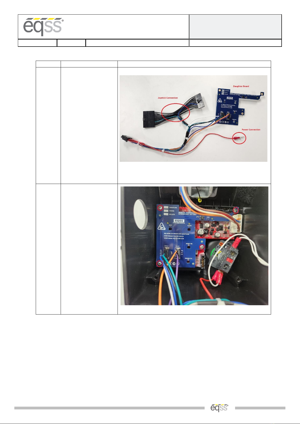
Installation Instructions......................................................................................................................................................6
Operator Sensor............................................................................................................................................................. 6
Control Module............................................................................................................................................................10
Post Installation Configuration .........................................................................................................................................17
Overview...................................................................................................................................................................... 17
Minimum system requirements .................................................................................................................................. 17
Wi-Fi Connection & Web Page Access .........................................................................................................................17
Machine Model Selection ............................................................................................................................................18
Installation Test............................................................................................................................................................ 19
Change Model Configuration.......................................................................................................................................20
System Settings.................................................................................................................................................................21
Default Parameters...................................................................................................................................................... 21
Polarity and Input Style................................................................................................................................................ 22
Harness Drawing AS001928..............................................................................................................................................23
Replacement Parts............................................................................................................................................................ 24

EQUIPMENT SAFETY SYSTEMS
75 Naxos Way, Keysborough 3173 Victoria Australia
P: +61 3 8770 6555 E: support@eqss.com.au
Genie Smartlink
Installation Manual
REV 2.4
28/11/2023
Model6253 OverWatch™Installation Manual
Document # DO001205
|5 of 24|
Preparation
Required Tools
The OverWatch has been designed to be fitted using basic workshop tools. Shown below is a list of tools required
to complete the installation.
Item
Tool / Description
1
Electric Drill
2
Centre Punch
3
Hammer
4
Side Cutters
5
Drill 5.0mm
6
Drill 6.0mm
7
Sockets & Spanners
8
Needle Nose Pliers
9
Screwdrivers
10
Hot glue and hot glue gun
Installation Time
The suggested time required to install the OverWatch is detailed below.
Task
Estimated Time (Minutes)
Open the operator control box
5
Drilling of all mounting holes for the various components
10
Mechanical assembly
10
Electrical assembly
30
Post installation system tests
10
Close the operator control box
5
Total
70

EQUIPMENT SAFETY SYSTEMS
75 Naxos Way, Keysborough 3173 Victoria Australia
P: +61 3 8770 6555 E: support@eqss.com.au
Genie Smartlink
Installation Manual
REV 2.4
28/11/2023
Model6253 OverWatch™Installation Manual
Document # DO001205
|6 of 24|
Installation Instructions
Operator Sensor
Step
Description
Diagram
1.
Remove the Joystick
controller from the
metal housing.
2.
Drill two 6mm holes to
mount the operator
sensor in the position
shown in the diagram.
Hole #1: 25mm from the
top horizontal edge and
34mm from the left
vertical edge.
Hole #2: 42mm vertically
down from the centre of
the hole 1and 45mm
horizontal. The distance
between the two holes is
61mm.
Note: The sensor should
be mounted at an angle
of 40 degrees from the
vertical.

EQUIPMENT SAFETY SYSTEMS
75 Naxos Way, Keysborough 3173 Victoria Australia
P: +61 3 8770 6555 E: support@eqss.com.au
Genie Smartlink
Installation Manual
REV 2.4
28/11/2023
Model6253 OverWatch™Installation Manual
Document # DO001205
|7 of 24|
Step
Description
Diagram
3.
Drill two 5.0mm holes
for the P-clips at the rear
and side as shown in the
image.

EQUIPMENT SAFETY SYSTEMS
75 Naxos Way, Keysborough 3173 Victoria Australia
P: +61 3 8770 6555 E: support@eqss.com.au
Genie Smartlink
Installation Manual
REV 2.4
28/11/2023
Model6253 OverWatch™Installation Manual
Document # DO001205
|8 of 24|
Step
Description
Diagram
4.
Sensor Mounting Guard
V1 (ME001794)
Mount the operator
sensor in the 40-degree
position by using the
wedges, sensor guard,
bolts, and washers.
The orientation of the
wedge blocks is critical
for the correct
positioning of the
operator sensor. Make
sure that the sensor is
angled, such that it is
twisted outwards from
the joystick controller.
5.
Sensor Mounting Guard
V2 (AS002326)
This bracket (AS002326)
supersedes the original
V1 design. Attach the
bracket in position using
the M5 nuts and
washers. Make sure that
the sensor is on the 7.5-
degree angle, such that
it is twisted outwards
from the joystick
controller.
The 7.5-degree twist is
achieved by rotating the
sensor inside the
assembly and using the
bolt hole as show in the
image.

EQUIPMENT SAFETY SYSTEMS
75 Naxos Way, Keysborough 3173 Victoria Australia
P: +61 3 8770 6555 E: support@eqss.com.au
Genie Smartlink
Installation Manual
REV 2.4
28/11/2023
Model6253 OverWatch™Installation Manual
Document # DO001205
|9 of 24|
Step
Description
Diagram
6.
Route the operator
sensor cable as shown in
the diagram. Use P-Clips
to secure the cable to
the metal enclosure.

EQUIPMENT SAFETY SYSTEMS
75 Naxos Way, Keysborough 3173 Victoria Australia
P: +61 3 8770 6555 E: support@eqss.com.au
Genie Smartlink
Installation Manual
REV 2.4
28/11/2023
Model6253 OverWatch™Installation Manual
Document # DO001205
|10 of 24|
Control Module
Step
Description
Diagram
1.
Remove the bottom
plastic cover from the
joystick to expose the
inside wiring and
electronics.
2.
Remove the buzzer, E-
Stop, and the Genie
circuit board.

EQUIPMENT SAFETY SYSTEMS
75 Naxos Way, Keysborough 3173 Victoria Australia
P: +61 3 8770 6555 E: support@eqss.com.au
Genie Smartlink
Installation Manual
REV 2.4
28/11/2023
Model6253 OverWatch™Installation Manual
Document # DO001205
|11 of 24|
Step
Description
Diagram
3.
Drill 20mm hole to run
the operator sensor
gland into the plastic
joystick enclosure. The
position of the hole is
detailed as in the image.
It is recommended to
use a step drill for this
hole.
4.
Use a fine metal pick to
clean the area shown in
the yellow circles, on the
adjacent image, to allow
access to the pins and
mounting holes.
This process removes
the conformal coating on
the PCB and allows
electrical access to the
drive, elevate, and horn
connections on the
circuit board.

EQUIPMENT SAFETY SYSTEMS
75 Naxos Way, Keysborough 3173 Victoria Australia
P: +61 3 8770 6555 E: support@eqss.com.au
Genie Smartlink
Installation Manual
REV 2.4
28/11/2023
Model6253 OverWatch™Installation Manual
Document # DO001205
|12 of 24|
Step
Description
Diagram
5.
Use a fine pair of side
cutters to trim down the
signal pins. These
connections must be
trimmed to be as flat as
possible so that the
spring pins from the
OverWatch daughter
board can make suitable
contact.
6.
Trim down the Elevate
signal pin. This pin is
located as displayed in
the image. Using a fine
pair of side cutters make
sure that the pin is
trimmed flat.

EQUIPMENT SAFETY SYSTEMS
75 Naxos Way, Keysborough 3173 Victoria Australia
P: +61 3 8770 6555 E: support@eqss.com.au
Genie Smartlink
Installation Manual
REV 2.4
28/11/2023
Model6253 OverWatch™Installation Manual
Document # DO001205
|13 of 24|
Step
Description
Diagram
7.
Trim down the Drive
signal pin. This pin is
located as displayed in
the adjacent image.
Using a fine pair of side
cutters make sure that
the pin is trimmed flat.
8.
Trim down the two Horn
signal pins. These pins
are located as displayed
in the adjacent image.
Using a fine pair of side
cutters make sure that
the pins are trimmed
flat.

EQUIPMENT SAFETY SYSTEMS
75 Naxos Way, Keysborough 3173 Victoria Australia
P: +61 3 8770 6555 E: support@eqss.com.au
Genie Smartlink
Installation Manual
REV 2.4
28/11/2023
Model6253 OverWatch™Installation Manual
Document # DO001205
|14 of 24|
Step
Description
Diagram
9.
Wiring connections are
made with the
OverWatch harness
AS001928.
Supplied with the
harness is the following
hardware:
4 x 6.4mm spacers
4 x G4x19mm Bolts
These hardware
components are critical
and must be used to
space the daughter
board above the Genie
circuit board
10.
Mount the Overwatch
daughter board on top
of the Genie circuit
board by using the
provided screws and
spacers in the kit.
Make sure that the
board is sitting in the
correct position and the
spring pins are
contacting the Genie
circuit board signal
points.

EQUIPMENT SAFETY SYSTEMS
75 Naxos Way, Keysborough 3173 Victoria Australia
P: +61 3 8770 6555 E: support@eqss.com.au
Genie Smartlink
Installation Manual
REV 2.4
28/11/2023
Model6253 OverWatch™Installation Manual
Document # DO001205
|15 of 24|
Step
Description
Diagram
11.
Joystick connection:
Install the Overwatch
connectors in between
the joystick and the
Genie circuit board
connector.
Visually check that all
pins from original
joystick connector have
a corresponding cable on
the Overwatch harness.
Reconnect the other
connectors, which were
disconnected in step 2.
12.
Power Connection:
At the back of the E-
Stop, install the
OverWatch red power
cable to terminal 2 of
the E-Stop.
Note: This cable might
need to be changed to
terminal 1 if the
Overwatch is powered
with the E-Stop pushed
in.

EQUIPMENT SAFETY SYSTEMS
75 Naxos Way, Keysborough 3173 Victoria Australia
P: +61 3 8770 6555 E: support@eqss.com.au
Genie Smartlink
Installation Manual
REV 2.4
28/11/2023
Model6253 OverWatch™Installation Manual
Document # DO001205
|16 of 24|
Step
Description
Diagram
13.
Mount the control
module in the location
shown in the image
using the velcro tape.
Run the operator sensor
cable through the 20mm
hole and secure the
cable gland.
Connect the 8-pin
connector from the
Operator Sensor and the
12-pin connector from
the machine connection
loom to the ECU.
14.
Re-assemble the control
box and mount the
joystick controller back
onto the to the metal
shroud.
Make sure the operator
sensor cable runs clear
to the joystick and
tighten the M20 gland to
seal the cable entry
point.

EQUIPMENT SAFETY SYSTEMS
75 Naxos Way, Keysborough 3173 Victoria Australia
P: +61 3 8770 6555 E: support@eqss.com.au
Genie Smartlink
Installation Manual
REV 2.4
28/11/2023
Model6253 OverWatch™Installation Manual
Document # DO001205
|17 of 24|
Post Installation Configuration
Overview
After the system has been installed it must be configured with the parameters to suit the machine. Follow the
instructions below to configure the OverWatch.
Minimum system requirements
Any smart phone, tablet or laptop that meets the following requirements:
•The device can connect to a Wi-Fi access point
•The device has an up to date web browser installed. Firefox, Chrome or Safari are recommended.
Wi-Fi Connection & Web Page Access
To enable the Wi-Fi connection on the OverWatch to complete the configuration follow the steps below.
1. Power down the platform control box with the ESTOP
2. Wait 5 seconds
3. Power up the platform control box with the ESTOP
4. While standing in front of the operator sensor, switch on the OverWatch
5. As the welcome chime starts to play, cover the sensor. The LED will flash white then black to acknowledge.
6. Remove your hand from the sensor. The LED will flash white then black to acknowledge.
7. After covering then uncovering the sensor this way 2 more times, "Wi-Fi On" will be announced
8. On your Wi-Fi enabled device (laptop, tablet, smartphone, etc), show the available wireless networks
9. Select the wireless network (starts with “overwatch”) to connect to the OverWatch
10. When prompted, enter the password 12345678
11. Open your preferred web browser (Chrome, Firefox, Safari)
12. Enter the following into the address bar http://192.168.4.1 to open the OverWatch main page

EQUIPMENT SAFETY SYSTEMS
75 Naxos Way, Keysborough 3173 Victoria Australia
P: +61 3 8770 6555 E: support@eqss.com.au
Genie Smartlink
Installation Manual
REV 2.4
28/11/2023
Model6253 OverWatch™Installation Manual
Document # DO001205
|18 of 24|
Machine Model Selection
Follow the instructions below to configure the OverWatch.
1. Select the Setup option
2. If there is a password field at the bottom of the page, follow the instructions in Change Model Configuration
to obtain the password and enter the password field
3. Select the EWP Model from the drop-down list and click Set
4. Click on Proceed to test to begin the installation test

EQUIPMENT SAFETY SYSTEMS
75 Naxos Way, Keysborough 3173 Victoria Australia
P: +61 3 8770 6555 E: support@eqss.com.au
Genie Smartlink
Installation Manual
REV 2.4
28/11/2023
Model6253 OverWatch™Installation Manual
Document # DO001205
|19 of 24|
Installation Test
After the model configuration has been set or updated an Installation Test must be performed. This will ensure the
installation has been correctly performed and the OverWatch is functioning correctly. Follow the instructions on
the web page to complete the Installation Test.

EQUIPMENT SAFETY SYSTEMS
75 Naxos Way, Keysborough 3173 Victoria Australia
P: +61 3 8770 6555 E: support@eqss.com.au
Genie Smartlink
Installation Manual
REV 2.4
28/11/2023
Model6253 OverWatch™Installation Manual
Document # DO001205
|20 of 24|
Change Model Configuration
To reconfigure the OverWatch for a different model requires an authorisation password. The authorisation
password is generated from the EQSS website. The EQSS website requires a login username and password, contact
EQSS for these details.
Follow the instructions below to obtain an authorisation password. It is important to note that each ECU has a
unique serial number and a unique password.
1. Open your web and enter the following into the address bar http://www.eqss.com.au/overwatch to open the
Login page
2. Enter your username and password
3. Enter the EUC serial number which is shown on the setup page or on the ECU serial number sticker, also
enter the owner and model details of the EWP and then click Generate Hash
4. The generated Hash code or password can be used to change the model configuration.
Genie Smartlink
Other manuals for OverWatch 6253
11
Table of contents
Other eqss Control System manuals

eqss
eqss Gen-3 LMS User manual

eqss
eqss OverWatch 6253 User manual

eqss
eqss OverWatch 6253 User manual

eqss
eqss OverWatch Sinoboom RD-RT Series User manual

eqss
eqss OverWatch 6253 User manual

eqss
eqss Gen-3 LMS User manual

eqss
eqss OverWatch Genie GR-12 User manual

eqss
eqss Genie GEN-5 Series User manual

eqss
eqss OverWatch Dingli ACE Series User manual

eqss
eqss OverWatch Dingli S03-ACE Series User manual