eqss Gen-3 LMS User manual

EQUIPMENT SAFETY SYSTEMS PTY LTD
eqss™ Gen-3 LMS
Telehandler Load Management System
Installation Manual for MLT840
Manual Tool Re ognition
VER: 20150513
Failure To Follow Installation Manual Will Void Warranty

Do umentation Conventions
The list below highlights important do umentation onventions.
Text presented in this manner is intended to provide the user
with some general information. The user should ensure
information presented in this manner is clearly understood.
Text presented in this manner provides the user with
information to assist in completion of the current procedure
being explained.
Text presented in this manner indicates that a failure to follow
directions could result in damage to equipment, loss of
information, bodily harm, or loss of life.
VER: 20150513 2 of 47

Important Information
Information ontained in this publi ation regarding this devi e's appli ations and the like is
provided only for your onvenien e and may be superseded by updates. It is your
responsibility to ensure that the appli ation or our equipment meets with your
spe ifi ations.
EQUIPMENT SAFETY SYSTEMS MAKE NO REPRESENTATIONS OR WARRANTIES
OF ANY KIND WHETHER EXPRESS OR IMPLIED, WRITTEN OR ORAL, STATUTORY
OR OTHERWISE, RELATED TO THE INFORMATION, INCLUDING BUT NOT LIMITED
TO ITS CONDITION, QUALITY, PERFORMANCE, MERCHANTABILITY OR FITNESS
FOR PURPOSE.
Equipment Safety Systems dis laims all liability arising from this information and its use.
Use of Equipment Safety Systems’ produ ts as riti al omponents in life support systems
is not authorised ex ept with express written approval by Equipment Safety Systems. No
li enses are onveyed, impli itly or otherwise, under any Equipment Safety Systems
intelle tual property rights.
VER: 20150513 3 of 47

Table of Contents
Tools Required for Installation.....................................................................................6
Installation Index...........................................................................................................7
overs.........................................................................................................................11
able Reeler Installation.............................................................................................13
able Reeler Mounting Position.............................................................................15
Pressure Sensor Installation.......................................................................................16
Main Lift ylinder – Standard onfiguration..........................................................16
Main Lift ylinder – Boom Suspension Option.......................................................18
ompensation Pressure Sensors............................................................................20
Reverse amera..........................................................................................................21
utout able Harness.................................................................................................23
Forward amera..........................................................................................................26
Light Tower Installation..............................................................................................28
Light Tower Bracket Mounting Position................................................................29
Machine Input Harness...............................................................................................30
an Pressure Input Module ( PIM)............................................................................31
External able ompletion.........................................................................................32
Display Installation......................................................................................................34
User Input ontrol.......................................................................................................35
an abin Interface Module ( IM)...........................................................................36
Override Wiring...........................................................................................................37
abin Loom..................................................................................................................38
Finalisation..................................................................................................................41
Sensor alibration.......................................................................................................44
VER: 20150513 4 of 47


Tools Required for Installation
The tools required to perform the installation of the TSS are listed below
•Pen il or Texta
•Drill
•Drill bits
◦3.3 mm
◦4.5 mm
◦5 mm
◦6.25 mm
◦6.8 mm
◦8.5 mm
•Centre pun h
•Tap T-Handle
•Taps
◦M6
◦M7 x 0.75
◦M8
•Drill and tap oil
•Metri Allen keys
•Phillips Head s rew driver
•Spanners and so kets
◦7 mm
◦10 mm
◦13 mm
•Lo ktite thread lo ker
•Side utters
•Stanely knife
•Crimpers
•Wire strippers
VER: 20150513 6 of 47

Installation Index
The omponents and ables of the Gen-3 Telehandler Load Management System are
outline in the tables below. The following pages show where the omponents are installed
and the able routing.
See the appropriate manual se tion for a detailed installation des ription for ea h
omponent.
Refer to this section for any component placement or cable
routing issues
Item omponent Description
1 able Reeler
2 Main Lift ylinder Pressure Sensors
3 ompensation ylinder Pressure Sensors
4 an Pressure Input Module ( PIM)
5 Forward amera
6 Light Tower
7 Rear amera
8 an abin Interface Module ( IM)
9 Display Module
10 SPU Module
11 User ontrol Dial
12 Joystick onnection X67
Table 1: Component Installation Index
VER: 20150513 7 of 47

olour able Description
Yellow Boom able
Dark Green Main ylinder Pressure Sensor ables
Dark Blue ompensation ylinder Pressure Sensors ables
Light Blue Forward amera able
Violet Light Tower able
Aqua Rear amera able
Dark Yellow IM able
Light Green utout Harness
Red Display able
Orange User Input ontrol able
Brown Machine Input Harness
Table 2: Cable Installation Index
VER: 20150513 8 of 47

Illustration 1: Machine Boom
VER: 20150513 9 of 47

Illustration 2: Machine Chassis
VER: 20150513 10 of 47

Covers
Remove the following overs before starting the installation
Step Description Diagram
1. Remove the rear cover behind the
boom.
1. Remove the side panel next to the
cabin under the boom.
2. Remove the cover behind the cabin
VER: 20150513 11 of 47

Step Description Diagram
3. Inside the cabin remove the
dashboard display.
Table 3: Cover removal
VER: 20150513 12 of 47
Cable Reeler Installation
The able reeler is used to measure the boom extension to determine the maximum lifting
apa ity.
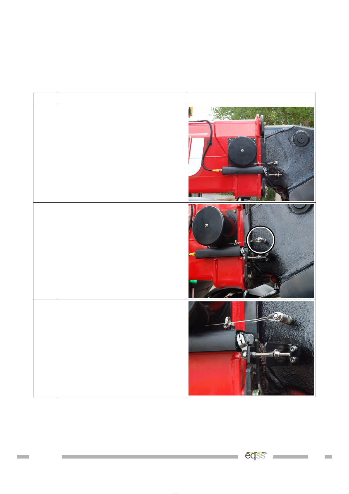
Step Description Diagram
1. Drill and tap the holes for the cable
reeler according to the mounting
diagram on page 15.
Mount using the supplied bolts and
washers.
2. Drill and tap an M8 hole for the
cable anchor. Ensure the cable
anchor is positioned so the cable
runs in line with the boom.
Mount the cable anchor and attach
the cable.
3. Drill and tap the M6 holes for the
stow switch trigger bracket.
Mount the stow switch trigger
bracket using the supplied M6 x 12
mm bolts and washers.
Adjust the length of the trigger plate
to ensure the stow switch is pressed
when the boom is retracted.
VER: 20150513 13 of 47
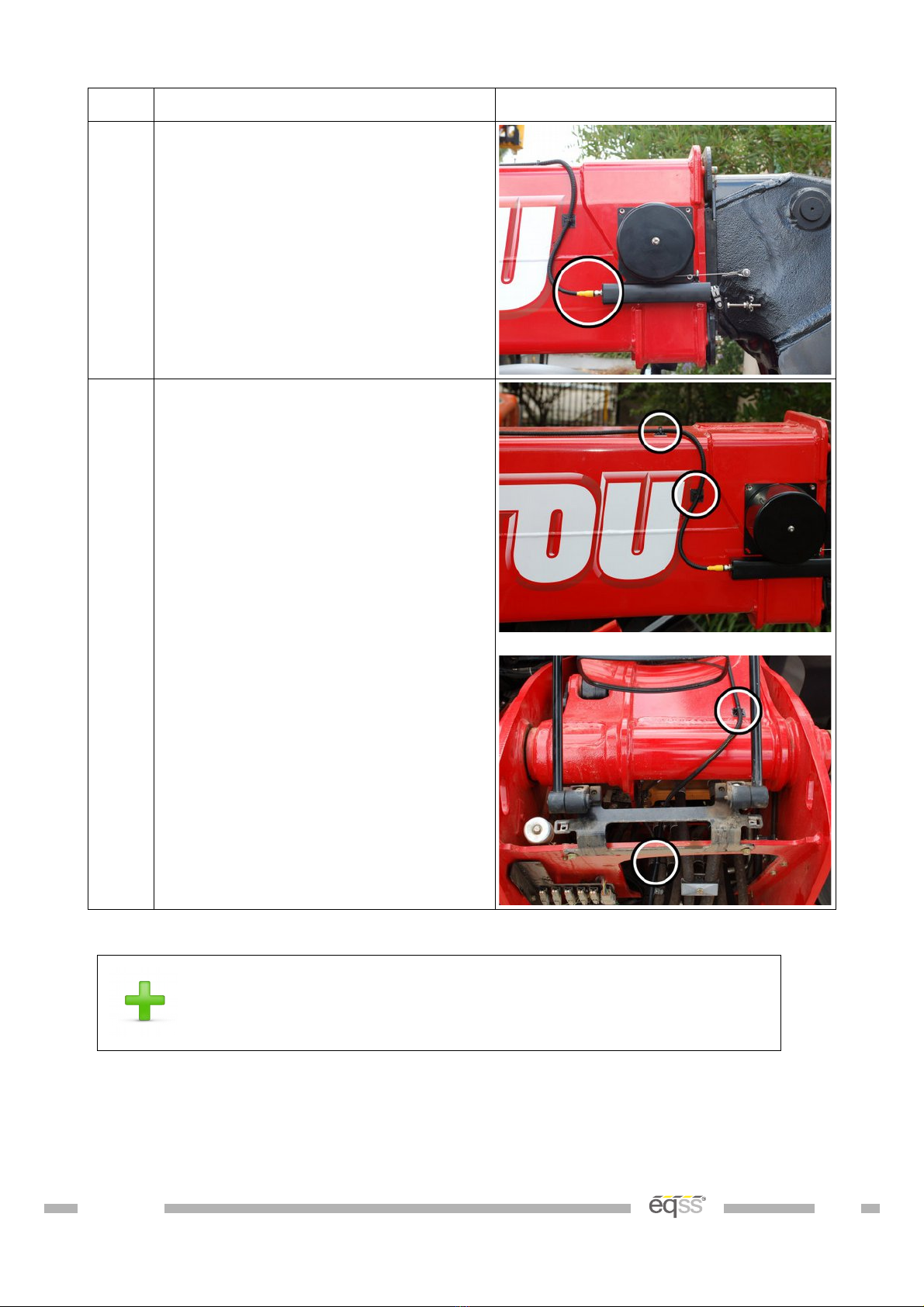
Step Description Diagram
4. onnect the supplied M12 10 metre
cable ( B001027) into the cable
reeler connection.
5. Run the cable down the top of the
boom, place cable tie points every
500 mm down the boom and secure
the cable to the cable tie points.
able tie to the flexible hydraulic
hoses down to the chassis. Make
sure the cable isn't pinched or
stretched when the boom is raised
or lowered.
Run the remainder of the cable out
the hole below the lift cylinder
towards the rear of the machine and
cable tie with the other cables
during External able ompletion on
page 32.
Table 4: Cable Reeler Installation
For further details on running the boom cable refer to the
Installation Index on page 7
VER: 20150513 14 of 47
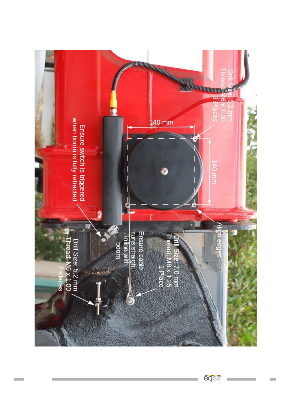
Cable Reeler Mounting Position
Illustration 3: Cable Reeler Mounting osition
VER: 20150513 15 of 47
Pressure Sensor Installation
The hydrauli pressure sensors are used to measure the lifting load of the telehandler.
Main Lift Cylinder – Standard Configuration
Failure to tighten the bolts to the correct torque on the
pressure manifold may result in a pressure failure on the
counterbalance valve causing an uncontrolled fall of the boom.
Step Description Diagram
1. Raise the boom to approximately 65
degrees, to access the bolts on the
counterbalance valve.
Support and secure the boom using
an A Frame or similar apparatus. It
must support at least 2 tons.
Apply the handbrake and insert
chock under wheels.
Remove the counterbalance valve on
the side of the hydraulic lifting ram.
Removing the counterbalance valve
will release the hydraulic pressure
which may result in a spray of oil.
Secure the pressure manifold using
the supplied 70 mm bolts and seals.
Tighten the bolts for the manifold to
25 NM using a torque wrench.
Start the machine, pressurise the
boom and check for leaks.
VER: 20150513 16 of 47
Step Description Diagram
2. onnect the supplied M12 4 metre
cables ( B001026) into each of the
pressure sensors.
able tie to the flexible hydraulic
hoses connected to the main lift
cylinder. Make sure the cable isn't
pinched or stretched when the boom
is raised or lowered.
Run the remainder of the cable out
the hole above the rear axle under
the lift cylinder towards the rear of
the machine and cable tie with the
other cables during External able
ompletion on page 32.
Table 5: Main Lift Cylinder – Standard Configuration
For further details on running the pressure sensor cables
refer to the Installation Index on page 7
VER: 20150513 17 of 47

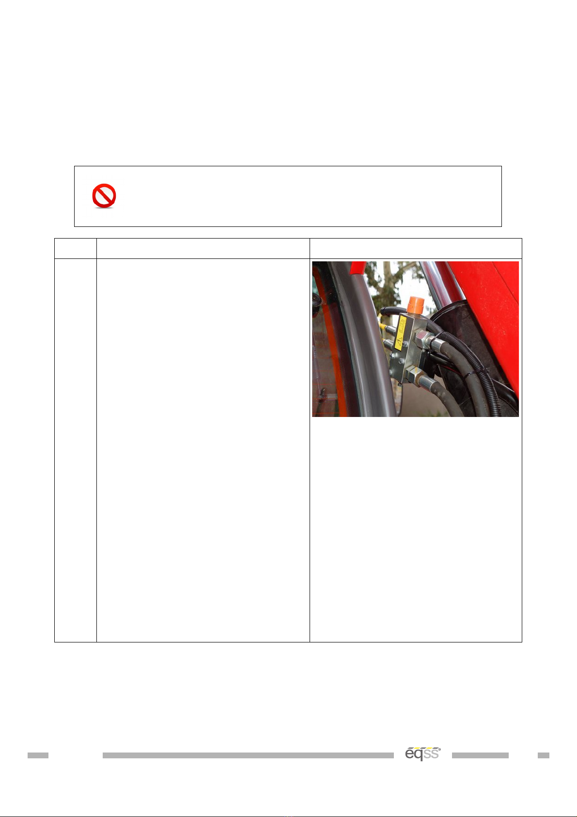
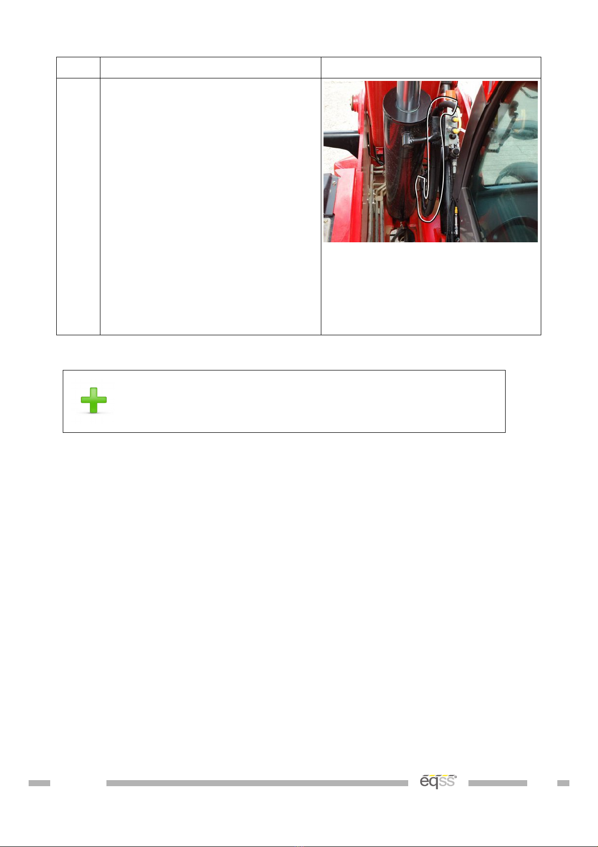
Main Lift Cylinder – Boom Suspension Option
Step Description Diagram
1. Raise the boom and support and
secure the boom using an A Frame
or similar apparatus. It must support
at least 2 tons.
Apply the handbrake and insert
chock under wheels.
Remove the pressure sensor
connected to the PX port of the main
head pressure line on the
counterbalance manifold.
Removing the pressure sensor from
the counterbalance manifold will
release the hydraulic pressure which
may result in a spray of oil.
onnect the supplied hydraulic
connections and pressure sensor
into the PX port of the
counterbalance manifold and connect
the existing pressure sensor into the
available port on the supplied
hydraulic connections, as shown in
the picture.
Ensure the hydraulic connections
are orientated as shown in the
picture, so the hydraulic connections
are not damaged when the boom is
lowered.
View from under the boom towards
the main lift cylinder
VER: 20150513 18 of 47

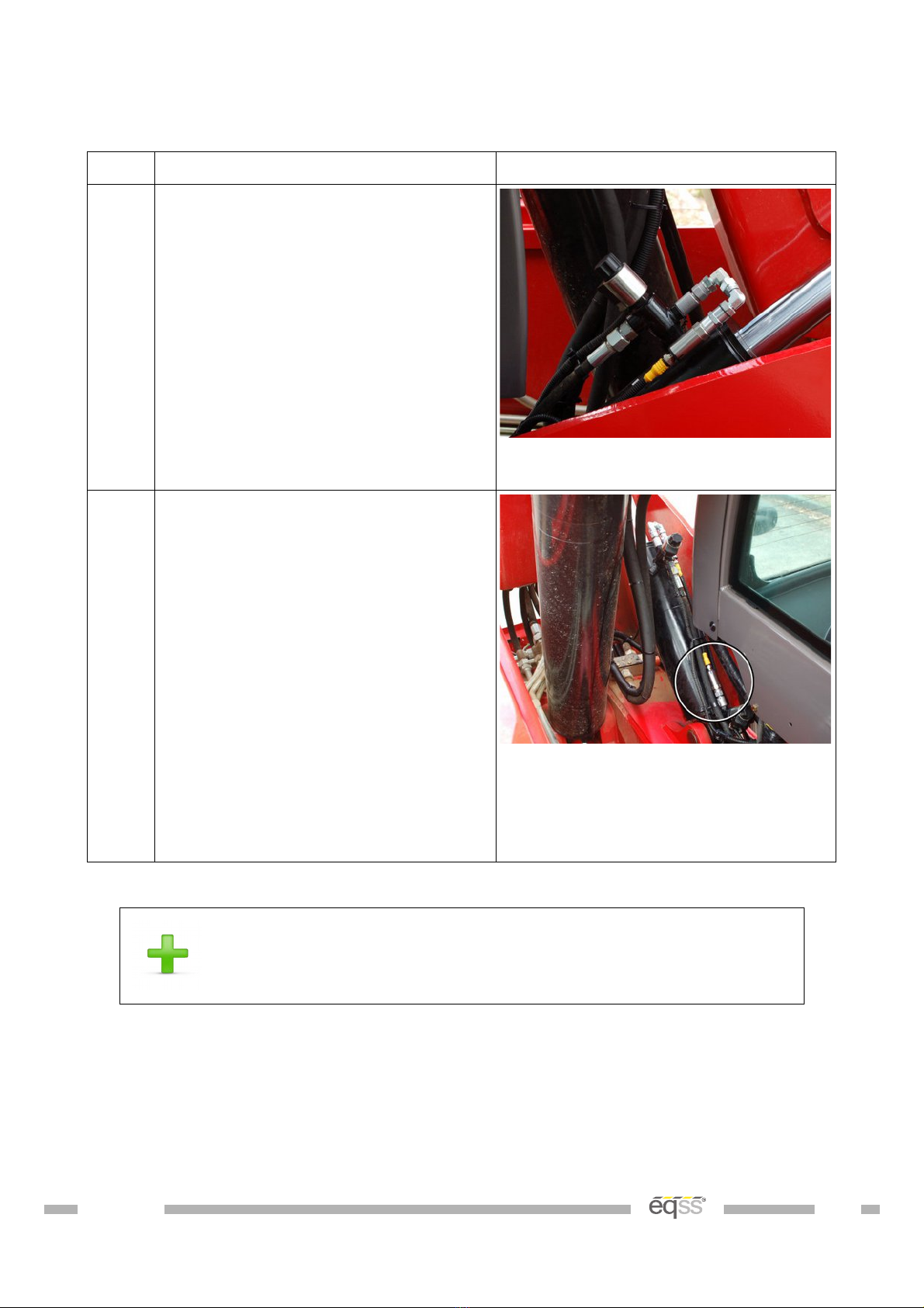
Step Description Diagram
2. Disconnect the hose coming from
the main rod pressure line into the
left side of the counterbalance
manifold mounted on the chassis.
onnect the supplied hydraulic tee
connection and pressure sensor into
the main rod pressure line.
Ensure the pressure sensor is
aligned as shown in the picture, so
the pressure sensor is not crushed
when the compensation cylinder is
moved.
Start the machine, pressurise the
boom and check for leaks.
View from under the compensation
cylinder
3. onnect the supplied M12 4 metre
cables ( B001026) into each of the
pressure sensors.
able tie the main head pressure
sensor cable to the flexible hydraulic
hoses connected to the main lift
cylinder. Make sure the cable isn't
pinched or stretched when the boom
is raised or lowered.
Run the remainder of the cable
towards the rear of the cabin and
cable tie with the other cables
during External able ompletion on
page 32.
Table 6: Main Lift Cylinder – Boom Suspension Option
For further details on running the pressure sensor cables
refer to the Installation Index on page 7
VER: 20150513 19 of 47
Compensation Pressure Sensors
Step Description Diagram
1. Install the pressure sensor with the
U shaped hydraulic connection into
the rod of the compensation cylinder
View from behind the cabin towards
the center of the machine
2. Install the head compensation
pressure sensor into the
compensation cylinder
Start the machine, pressurise the
boom and check for leaks.
onnect the supplied M12 4 metre
cables ( B001026) into each of the
pressure sensors.
Run the snake tube and cables
towards the cabin and cable tie with
the other cables during External
able ompletion on page 32.
View from under the boom towards
the rear of the machine
Table 7: Compensation ressure Sensor Installation
For further details on running the pressure sensor cables
refer to the Installation Index on page 7
VER: 20150513 20 of 47
Other manuals for Gen-3 LMS
11
Table of contents
Other eqss Control System manuals

eqss
eqss Gen-3 LMS User manual

eqss
eqss OverWatch 6253 User manual

eqss
eqss OverWatch Genie GR-12 User manual

eqss
eqss OverWatch Dingli ACE Series User manual

eqss
eqss OverWatch Dingli S03-ACE Series User manual

eqss
eqss OverWatch Sinoboom RD-RT Series User manual

eqss
eqss OverWatch 6253 User manual

eqss
eqss Overwatch JLG ES Series User manual

eqss
eqss Genie GEN-5 Series User manual

eqss
eqss OverWatch 6253 User manual


