eqss Gen-3 LMS User manual

EQUIPMENT SAFETY SYSTEMS PTY LTD
eqss™ Gen-3 LMS
Telehandler Load Management System
Installation Manual for MLT960
PL AS NOT :
VER: 1805241756
***Failure To Follow Installation Manual Will Void Warranty***
***Do Not Swap Components between Gen3-LMS kits***
When installing multiple Gen3-LMS kits, make sure the serial
number on the sticker matches the serial number on the
machine.

Documentation Conventions
The list below highlights important do umentation onventions.
Text presented in this manner is intended to provide the user
with some general information. The user should ensure
information presented in this manner is clearly understood.
Text presented in this manner provides the user with
information to assist in completion of the current procedure
being explained.
Text presented in this manner indicates that a failure to follow
directions could result in damage to equipment, loss of
information, bodily harm, or loss of life.
VER: 1805241756 2 of 53

Important Information
Information ontained in this publi ation regarding this devi e's appli ations and the like is
provided only for your onvenien e and may be superseded by updates. It is your
responsibility to ensure that the appli ation or our equipment meets with your
spe ifi ations.
EQUIPMENT SAFETY SYSTEMS MAKE NO REPRESENTATIONS OR WARRANTIES
OF ANY KIND WHETHER EXPRESS OR IMPLIED, WRITTEN OR ORAL, STATUTORY
OR OTHERWISE, RELATED TO THE INFORMATION, INCLUDING BUT NOT LIMITED
TO, IT'S CONDITION, QUALITY, PERFORMANCE, MERCHANTABILITY OR FITNESS
FOR PURPOSE.
Equipment Safety Systems dis laims all liability arising from this information and its use.
Use of Equipment Safety Systems’ produ ts as riti al omponents in life support systems
is not authorised ex ept with express written approval by Equipment Safety Systems. No
li enses are onveyed, impli itly or otherwise, under any Equipment Safety Systems
intelle tual property rights.
VER: 1805241756 3 of 53

Table of Contents
Tools Required for Installation.....................................................................................6
Installation Index...........................................................................................................7
overs.........................................................................................................................11
able Reeler Installation.............................................................................................13
able Reeler Mounting Position.............................................................................15
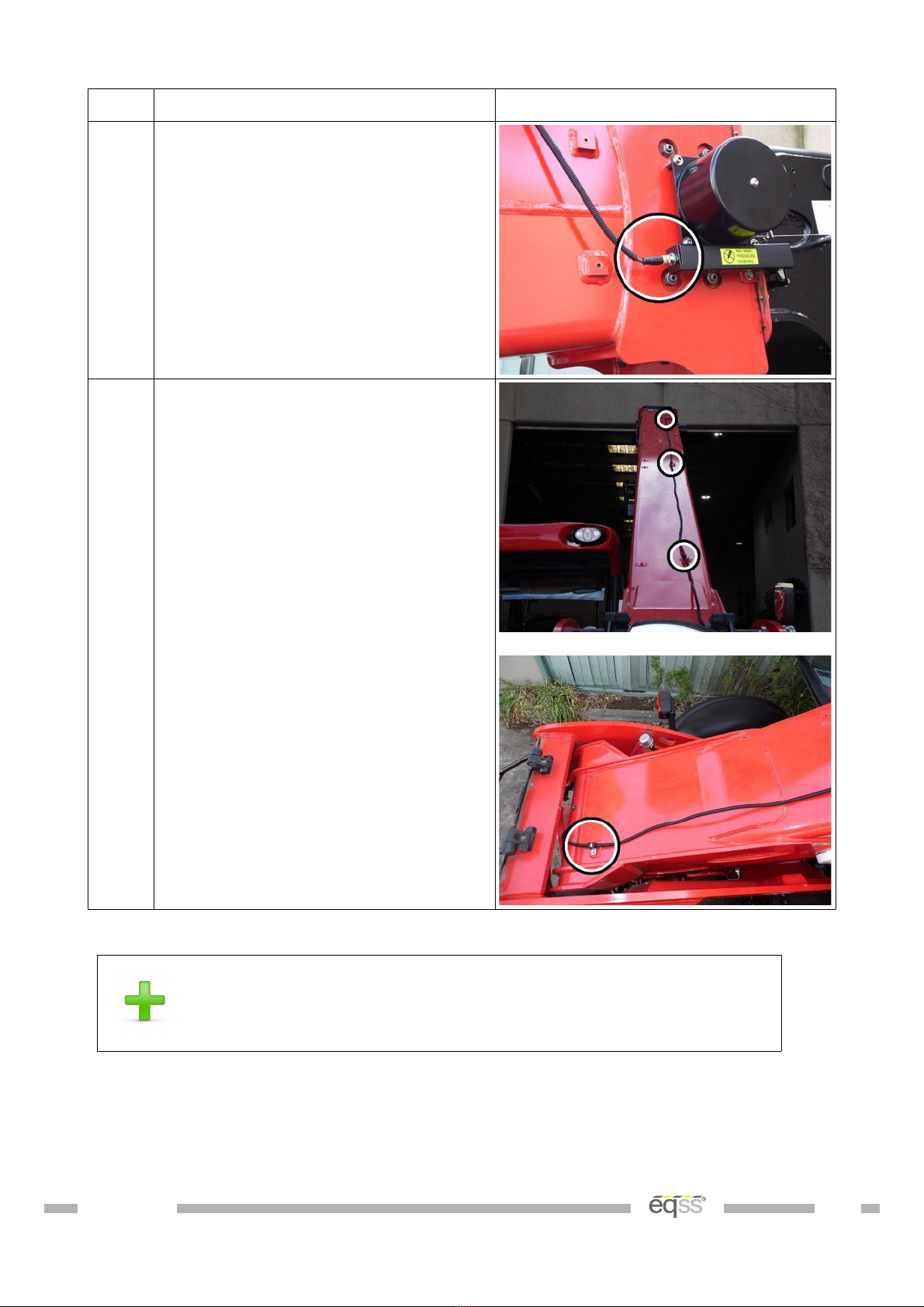
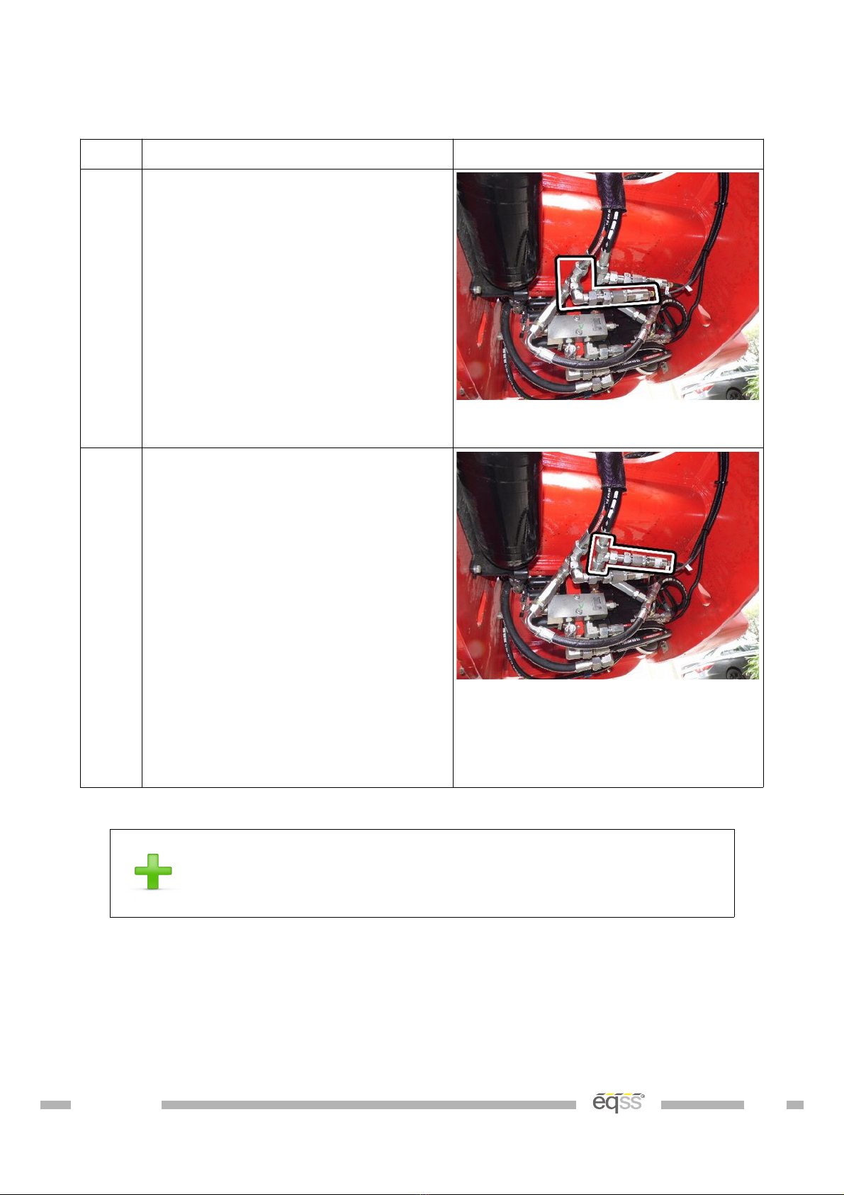
Pressure Sensor Installation.......................................................................................16
Main Lift ylinder...................................................................................................16
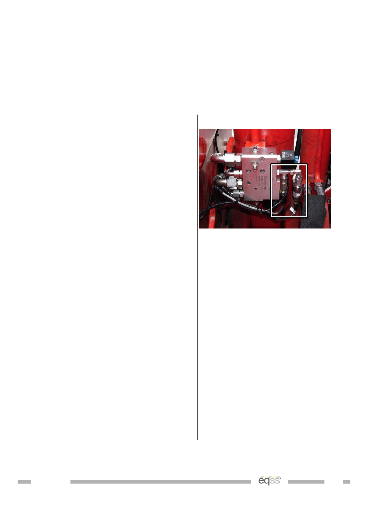
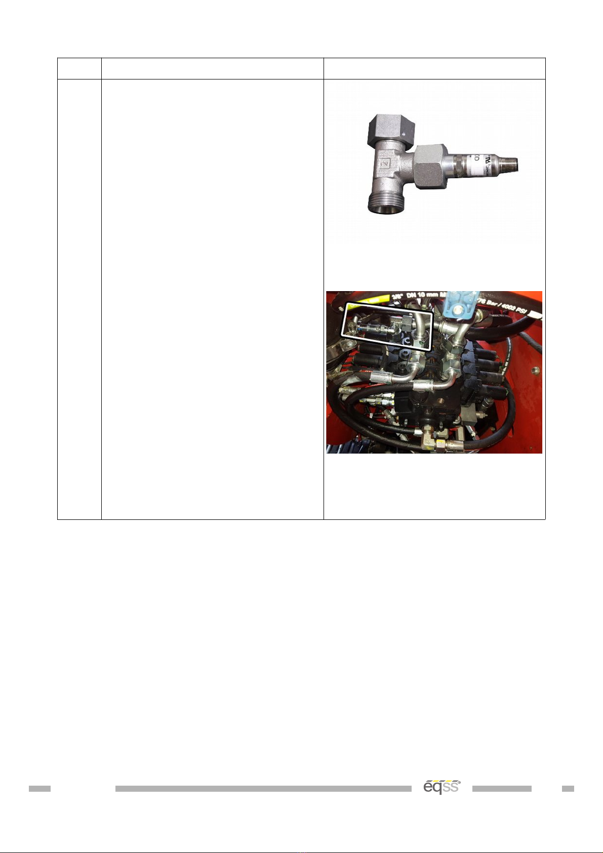
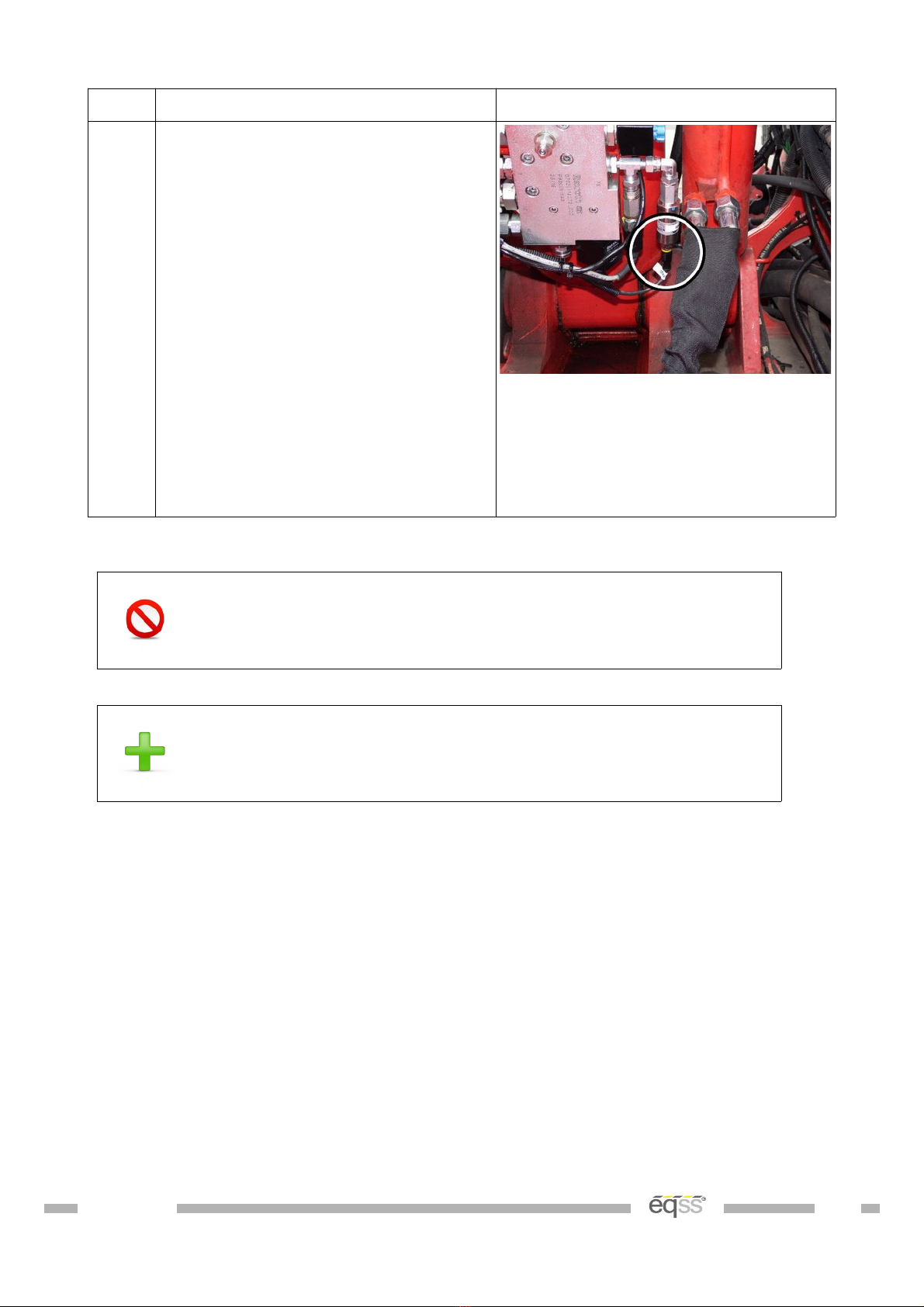
ompensation Pressure Sensors............................................................................19
Reverse amera..........................................................................................................20
utout able Harness.................................................................................................22
Forward amera..........................................................................................................25
Signal Light Installation..............................................................................................27
an Pressure Input Module ( PIM)............................................................................29
External able ompletion.........................................................................................30
Display Installation......................................................................................................32
User ontrol................................................................................................................33
an abin Interface Module ( IM)...........................................................................34
Machine Input Harness...............................................................................................35
Override Wiring...........................................................................................................36
abin Loom..................................................................................................................37
Finalisation..................................................................................................................40
Set Time & Sensor alibration...................................................................................44
Appendix A: Attaching Display onnectors...............................................................47
VER: 1805241756 4 of 53

Tools Required for Installation
The tools required to perform the installation of the TSS are listed below
•Pen il or Texta
•Drill
•Drill bits
◦3.3 mm
◦4.5 mm
◦5 mm
◦6.25 mm
◦6.8 mm
◦8.5 mm
•Centre pun h
•Tap T-Handle
•Taps
◦M6
◦M7 x 0.75
◦M8
•Drill and tap oil
•Metri Allen keys
•Phillips Head s rew driver
•Spanners and so kets
◦7 mm
◦10 mm
◦13 mm
•Lo ktite thread lo ker
•Side utters
•Stanely knife
•Crimpers
•Wire strippers
VER: 1805241756 6 of 53

Installation Index
The omponents and ables of the Gen-3 Telehandler Load Management System are
outline in the tables below. The following pages show where the omponents are installed
and the able routing.
See the appropriate manual se tion for a detailed installation des ription for ea h
omponent.
Refer to this section for any component placement or cable
routing issues
Item omponent Description
1 able Reeler
2 Main Lift ylinder Pressure Sensors
3 ompensation ylinder Pressure Sensors
4 an Pressure Input Module ( PIM)
5 Forward amera
6 Signal Light
7 Rear amera
8 an abin Interface Module ( IM)
9 Display Module
10 SPU Module
11 User ontrol Dial
12 Joystick onnection X67
Table 1: Component Installation Index
VER: 1805241756 7 of 53

olour able Description
Yellow Boom able
Dark Green Main ylinder Pressure Sensor ables
Dark Blue ompensation ylinder Pressure Sensors ables
Light Blue Forward amera able
Violet Light Tower able
Aqua Rear amera able
Dark Yellow IM able
Light Green utout Harness
Red Display able
Orange User Input ontrol able
Brown Machine Input Harness
Table 2: Cable Installation Index
VER: 1805241756 8 of 53

Covers
Remove the following overs before starting the installation
Step Description Diagram
1. Remove the rear covers behind the
boom.
2. Remove the first panel under the
chassis at the rear of the machine
3. Remove the first panel under the
chassis at the front of the machine
4. Remove the panels under the boom
VER: 1805241756 11 of 53

Cable Reeler Installation
The able reeler is used to measure the boom extension to determine the maximum lifting
apa ity.
A false N07 fault can occur if the boom jumps off the stow
switch due to pressurising the hydraulic system and without
operating the boom extension control. Ensure the stow switch
arm is correctly adjusted to prevent this error.
Step Description Diagram
1. Drill and tap the holes for the cable
reeler according to the mounting
diagram on page 15.
Mount on the supplied standoffs
using the supplied bolts and
washers.
2. Drill and tap an M8 hole for the
cable anchor. Ensure the cable
anchor is positioned so the cable
runs in line with the boom.
Mount the cable anchor and attach
the cable.
3. Drill and tap the M6 holes for the
stow switch trigger bracket.
Mount the stow switch trigger
bracket using the supplied standoffs
using the supplied bolts and
washers.
Ensure the stow switch is pressed
when the boom is retracted.
VER: 1805241756 13 of 53

Step Description Diagram
4. onnect the supplied M12 10 metre
cable ( B001027) into the cable
reeler connection.
5. Run the cable down the top of the
boom, and secure using the supplied
p-clips to the existing threaded
holes running down the boom.
able tie to the flexible hydraulic
hoses down to the chassis. Make
sure the cable isn't pinched or
stretched when the boom is raised
or lowered.
Run the remainder of the cable out
the hole below the lift cylinder
towards the rear of the machine and
cable tie with the other cables
during External able ompletion on
page 30.
Table 4: Cable Reeler Installation
For further details on running the boom cable refer to the
Installation Index on page 7
VER: 1805241756 14 of 53

Pressure Sensor Installation
The hydrauli pressure sensors are used to measure the lifting load of the telehandler.
Main Lift Cylinder
Step Description Diagram
1. Raise the boom and support and
secure the boom using an A Frame
or similar apparatus. It must support
at least 2 tons.
Apply the handbrake and insert
chock under wheels.
Remove the pressure sensor
connected to the PX port of the main
head pressure line on the
counterbalance manifold.
Removing the pressure sensor from
the counterbalance manifold will
release the hydraulic pressure which
may result in a spray of oil.
onnect the supplied hydraulic
connections and pressure sensor
into the PX port of the
counterbalance manifold and connect
the existing pressure sensor into the
available port on the supplied
hydraulic connections, as shown in
the picture.
Ensure the hydraulic connections
are orientated as shown in the
picture, so the hydraulic connections
are not damaged when the boom is
lowered.
View from under the boom towards
the main lift cylinder
VER: 1805241756 16 of 53

Step Description Diagram
2. Disconnect the hose coming from
the spool assembly for the main rod
pressure line.
Note: Some of the existing hoses
connected to the spool assembly will
need to be removed to access the
main rod pressure line.
onnect the supplied hydraulic tee
connection and pressure sensor into
the main rod pressure line.
Ensure the pressure sensor is
aligned as shown in the picture.
Start the machine, pressurise the
boom and check for leaks.
Note: The pressure sensor supplied
may differ from the photo above
View from under the machine to the
spool assembly
Note: The hydraulic connections
supplied differ from the photo above
VER: 1805241756 17 of 53

Step Description Diagram
3. onnect the supplied M12 4 metre
cables ( B001026) into each of the
pressure sensors.
able tie the main head pressure
sensor cable to the flexible hydraulic
hoses connected to the main lift
cylinder. Make sure the cable isn't
pinched or stretched when the boom
is raised or lowered.
Run the remainder of the cable
towards the rear of the cabin and
cable tie with the other cables
during External able ompletion on
page 30.
Table 5: Main Lift Cylinder – Boom Suspension Option
Angle the tee connections to ensure the hydraulic connections
and pressure sensor do not hit the boom when the boom is
lowered
For further details on running the pressure sensor cables
refer to the Installation Index on page 7
VER: 1805241756 18 of 53

Compensation Pressure Sensors
Step Description Diagram
1. Disconnect the flexible hydraulic
hoses connected to the
compensation cylinder under the
rear of the machine.
onnect the supplied hydraulic tee
connection and pressure sensor into
the compensation head pressure
line.
View from under the machine at the
rear
2. onnect the supplied hydraulic tee
connection and pressure sensor into
the compensation rod pressure line.
Start the machine, pressurise the
boom and check for leaks.
onnect the supplied M12 4 metre
cables ( B001026) into each of the
pressure sensors.
Run the snake tube and cables
towards the cabin and cable tie with
the other cables during External
able ompletion on page 30.
View from under the machine at the
rear
Table 6: Compensation ressure Sensor Installation
For further details on running the pressure sensor cables
refer to the Installation Index on page 7
VER: 1805241756 19 of 53

Reverse Camera
The rear amera video is displayed on the s reen when the ma hine is in reverse gear to
allow the operator to see behind the telehandler while reversing.
Do not disconnect the camera power connection while the
system is operating as this can damage the fuse.
Step Description Diagram
1. Drill a 31mm hole in the location
shown. Making sure to leave enough
room for a license plate
Insert the camera through the hole
and adjust the angle using the
alignment washers.
2. onnect the camera power and
signal connectors to the supplied 5m
camera cable ( B001032).
Note; The white connector is not
used.
Secure the camera cable using a
single cable tie to maintain the
connector location.
Run the remainder of the cable
towards the cabin and insert into
snake tube with the boom cable
during External able ompletion on
page 30.
Table 7: Reverse Camera Installation
VER: 1805241756 20 of 53
Other manuals for Gen-3 LMS
11
This manual suits for next models
1
Table of contents
Other eqss Industrial Equipment manuals
Popular Industrial Equipment manuals by other brands

Tronair
Tronair 01-0597-0000 Operation & service manual

Pregis
Pregis AIRSPEED 5000 Safety, operation and maintenance manual

ABB
ABB HT565235 Operation manual

Vertiv
Vertiv XTE 401 Series installation manual

Impact Pumps
Impact Pumps SLX-40 installation guide

TDW
TDW POLYSTOPP Operation and maintenance instruction