Erco&Gener GenPro 20e User manual

L’esprit Modem
User Guide
GenPro 20e
GenPro 24e
Reference : EG_GenProxxe_988_UG_008_UK
Revision : 008
Date : 24/06/2011
S.A. ERCO & GENER – ZI de St. Lambert-des-Levées – BP 30163 – F-49412 SAUMUR Cedex
Tél. : +33 (0)2 41 83 13 00 – Fax : +33 (0)2 41 67 19 20 – www.ercogener.com – infos@ercogener.com
SA CAPITAL 200873 €– R.C. SAUMUR B 332 174 820 – SIRET 332 174 820 00032 – NAF 322A – TVA Intra : FR 16 332 174 820

EG_GenProxxe_988_UG_008_UK Page 2 / 51
Descriptions and non-contractual illustrations in this document are given as an indication only.
ERCO&GENER reserves the right to make any modifications.
Document history
Revision Modifications Author Date
000 CREATION (Version UK) F. LE BRETON
M. REEVES 09/11/06
001 Modified schema 2-wire cable page 16.
Added Hardware WatchDog function page 11-30-35. F. LE BRETON 20/02/07
002 Checked functionnal architecture page 30.
Added ROHS directive page 50. F. LE BRETON 06/03/07
003
Removed Memory Flash 16 Mbits page 7.
Added warning SIM during the Firmware update (OS) page 26.
Modified Buzzer page 41. F. LE BRETON 19/03/07
004 Modified idle mode page 39. F. LE BRETON 18/07/07
005 Added Copyright chapter page 6.
Modified 2-wires micro FIT cable picture page 16. F. LE BRETON 11/02/08
006 Modified Warning page 13 F. LE BRETON 24/03/09
007 Suppress the GenPro 10e and the GenPro 14e YST 14/03/11
008 Added informations table of §
- 8.2.4 General purpose inputs / output YST 24/06/11
The main modifications in this document compared to its previous version, are easily identifiable on a
monitor by means of the blue text.

EG_GenProxxe_988_UG_008_UK Page 3 / 51
Descriptions and non-contractual illustrations in this document are given as an indication only.
ERCO&GENER reserves the right to make any modifications.
CONTENTS
PRESENTATION............................................................................................................................................... 5
WARNING ......................................................................................................................................................... 6
COPYRIGHT AND DISCLAIMER...................................................................................................................... 6
1 REFERENCES ............................................................................................................................................... 7
1.1 Product Differences ..................................................................................................................................... 7
1.2 Reference Documents................................................................................................................................. 8
1.3 Abreviations ................................................................................................................................................. 8
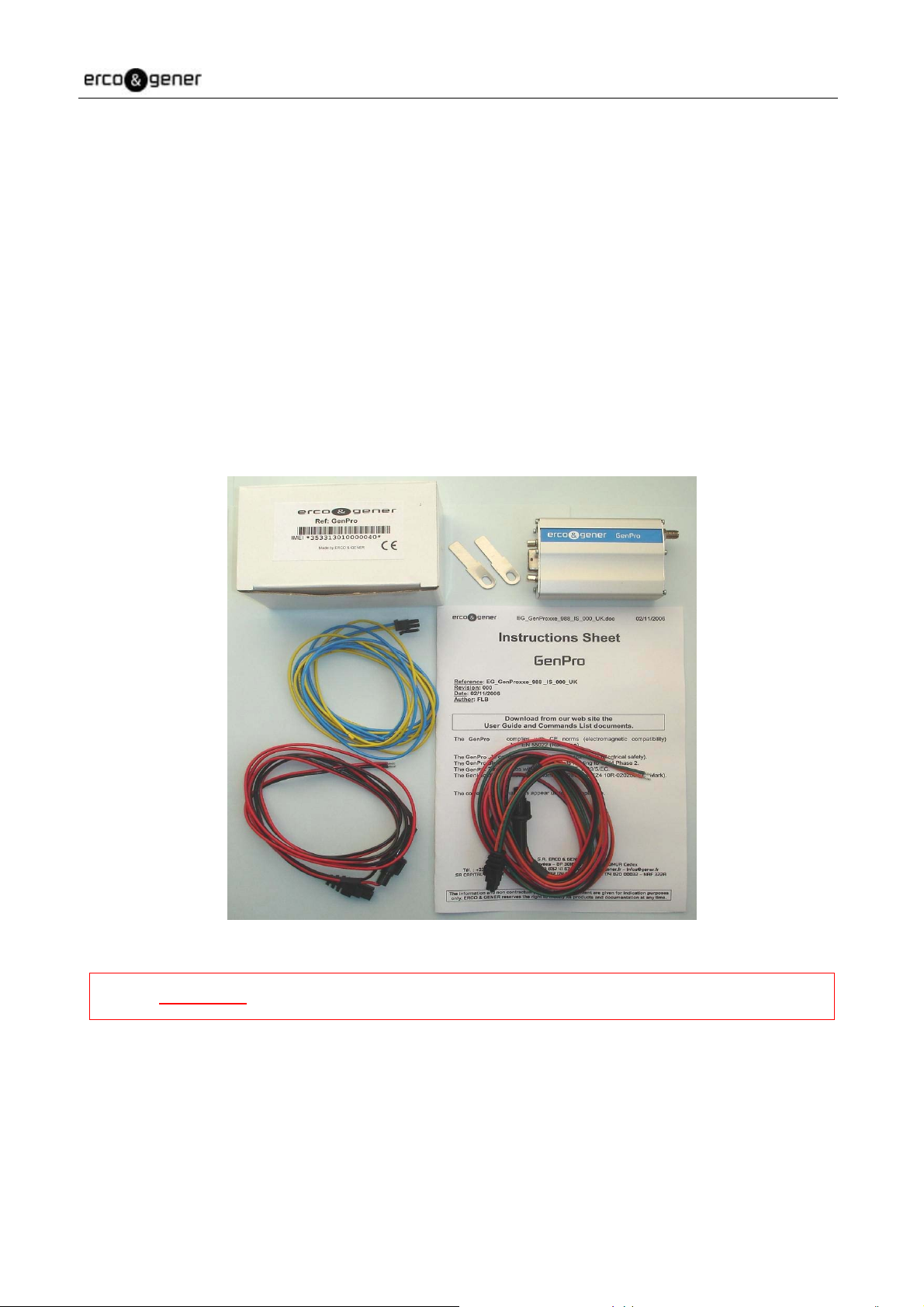
2 PACKING...................................................................................................................................................... 10
2.1 Contents .................................................................................................................................................... 10
2.2 Packing Case............................................................................................................................................. 11
2.3 Modem Labels ........................................................................................................................................... 11
3 GENERAL PRESENTATION ....................................................................................................................... 12
3.1 Physical Description .................................................................................................................................. 12
3.2 External connections ................................................................................................................................. 13
3.2.1 Connections ................................................................................................................................... 13
3.2.1.1 GSM antenna connector......................................................................................................... 13
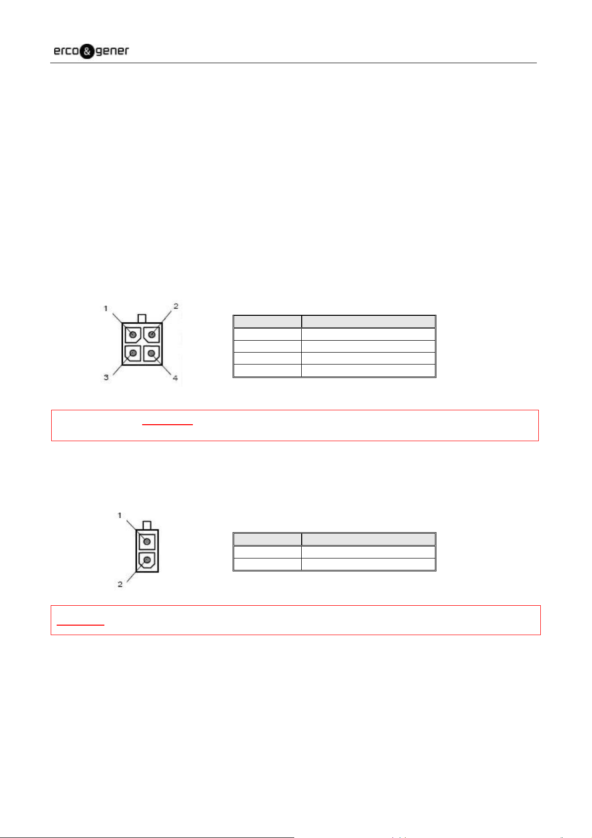
3.2.1.2 Micro FIT connectors.............................................................................................................. 13
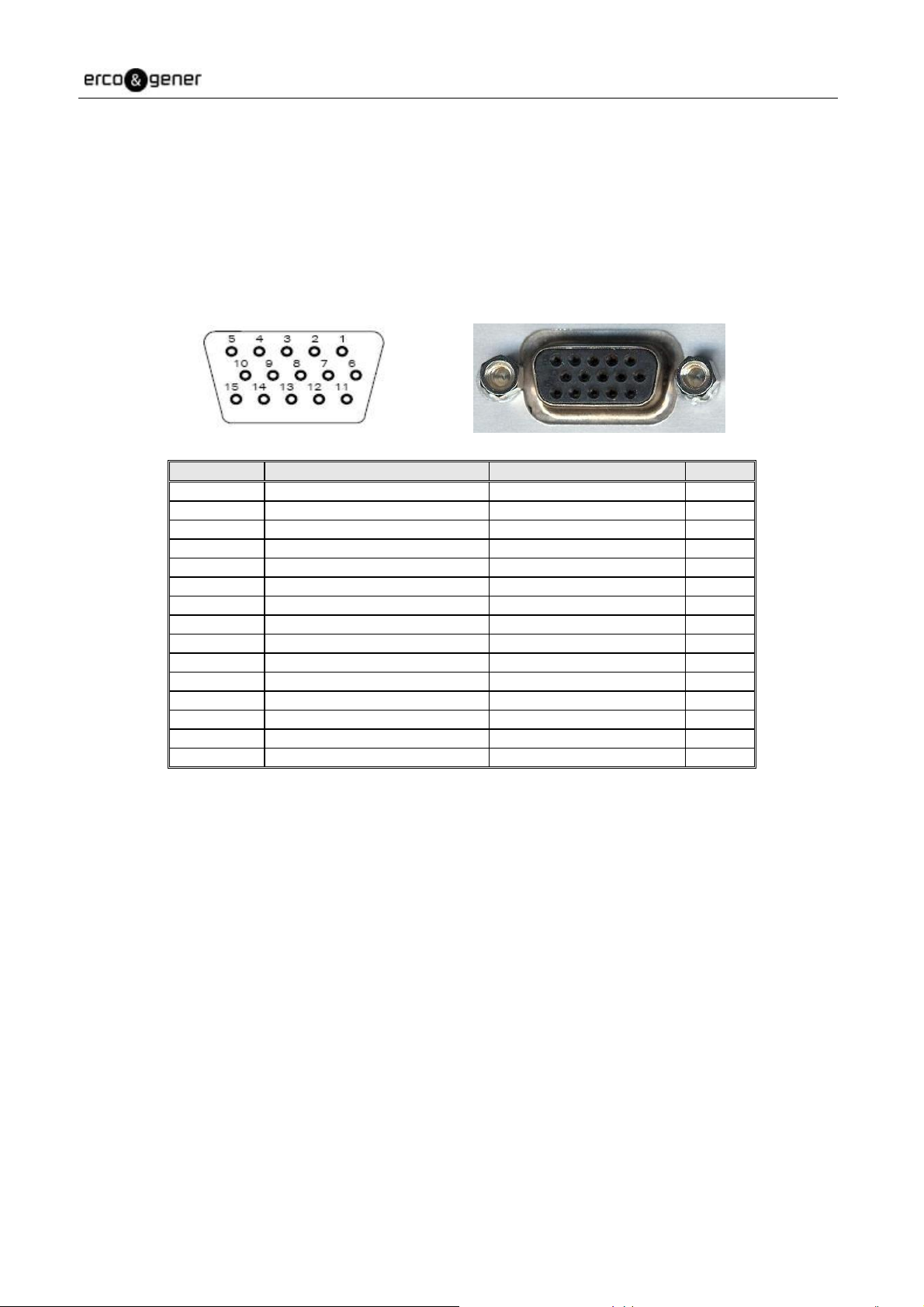
3.2.1.3 15-pin Sub HD female connector ........................................................................................... 14
3.2.2 Cables............................................................................................................................................ 15
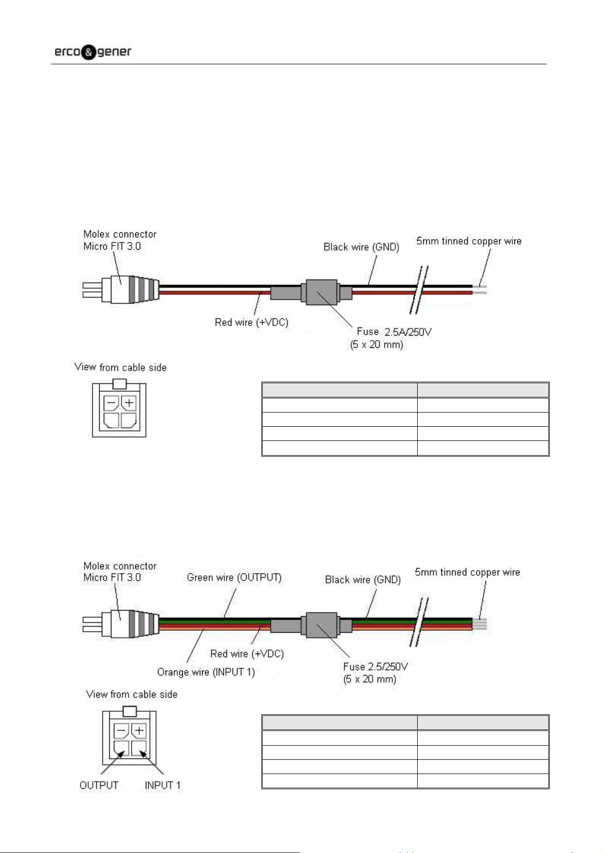
3.2.2.1 4-wire micro FIT supply cable................................................................................................. 15
3.2.2.2 4-wire micro FIT supply and input/output cable...................................................................... 15
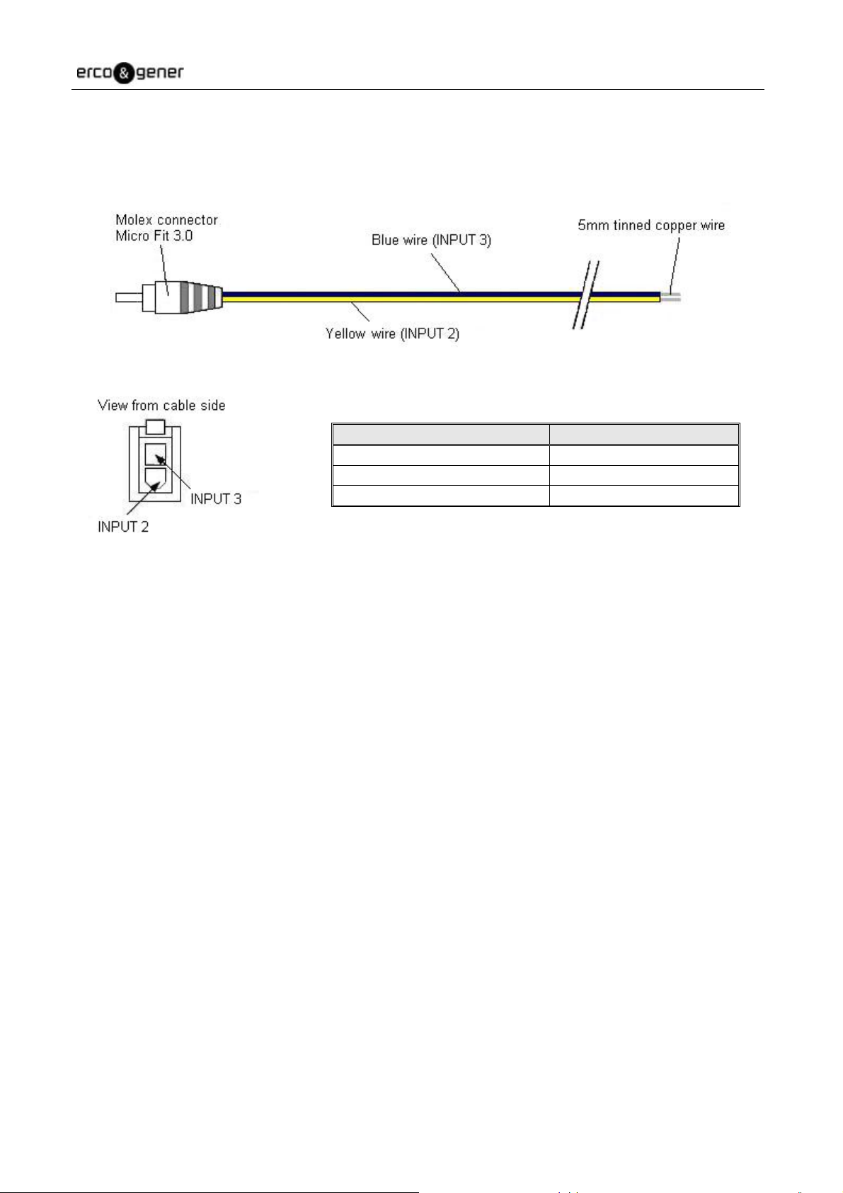
3.2.2.3 2-wire micro FIT inputs cable ................................................................................................. 16
4 CHARACTERISTICS AND SERVICES........................................................................................................ 17
5 USING THE MODEM ................................................................................................................................... 18
5.1 Starting with the modem............................................................................................................................ 18
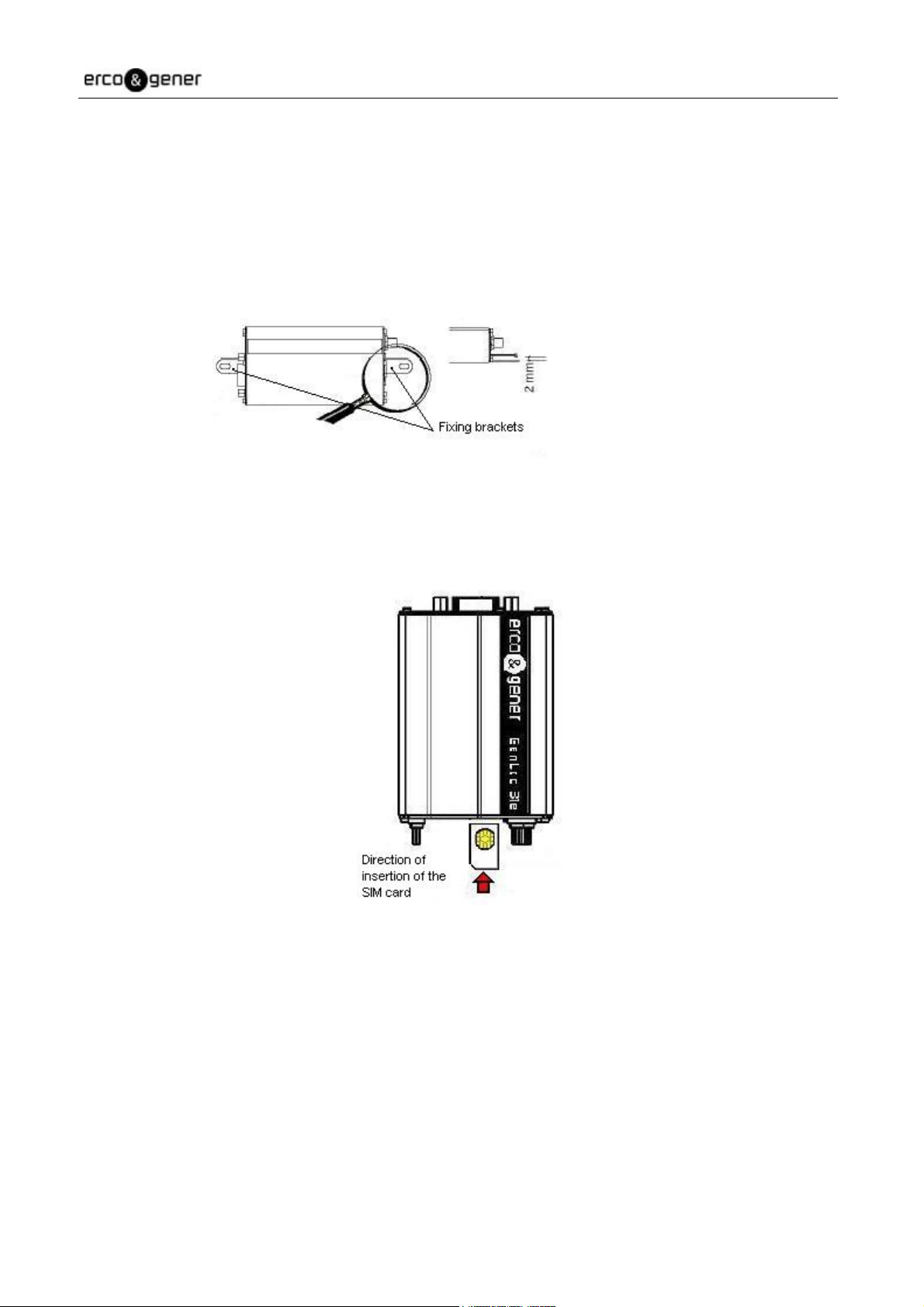
5.1.1 Mounting the modem ..................................................................................................................... 18
5.1.2 Installation of the modem............................................................................................................... 18
5.1.3 Communication with the modem ................................................................................................... 19
5.1.4 Re-initialisation of the modem ....................................................................................................... 19
5.2 Recommendations for using the modem in vehicles................................................................................. 20
5.2.1 Recommended connection to the battery in a lorry ....................................................................... 20
5.2.2 Technical constraints in lorries ...................................................................................................... 21
5.3 GSM indicator LED.................................................................................................................................... 22
5.4 AT commands Echo deactivated............................................................................................................... 22
5.5 Verifying GSM receive signal quality ......................................................................................................... 23
5.6 Verifying the PIN code............................................................................................................................... 24
5.7 Verifying modem registration on the GSM network................................................................................... 24
5.8 Main AT commands (HAYES) ................................................................................................................... 25
5.9 Powering down the unit ............................................................................................................................. 26
5.10 Updating the modem software................................................................................................................. 26
6 TROUBLE SHOOTING................................................................................................................................. 27
6.1 RS232 (V24) Communication problem...................................................................................................... 27
6.2 "ERROR" message.................................................................................................................................... 27
6.3 "NO CARRIER" message.......................................................................................................................... 28
7 FUNCTIONAL DESCRIPTION ..................................................................................................................... 30
7.1 Architecture................................................................................................................................................ 30
7.2 Power supply ............................................................................................................................................. 31
7.2.1 General .......................................................................................................................................... 31
7.2.2 Protection....................................................................................................................................... 31
7.3 RS232 serial link........................................................................................................................................ 32
7.3.1 General .......................................................................................................................................... 32
7.3.2 Auto-baud mode ............................................................................................................................ 33
7.3.3 Pins description.............................................................................................................................. 33
7.4 General Purpose Inputs / Output............................................................................................................... 33

EG_GenProxxe_988_UG_008_UK Page 4 / 51
Descriptions and non-contractual illustrations in this document are given as an indication only.
ERCO&GENER reserves the right to make any modifications.
7.5 BOOT......................................................................................................................................................... 34
7.6 RESET....................................................................................................................................................... 34
7.6.1 General .......................................................................................................................................... 34
7.6.2 RESET sequence .......................................................................................................................... 34
7.7 WatchDog .................................................................................................................................................. 35
7.8 Audio.......................................................................................................................................................... 35
7.8.1 Microphone .................................................................................................................................... 35
7.8.2 Loud-speaker ................................................................................................................................. 36
7.8.3 Buzzer output................................................................................................................................. 36
8 TECHNICAL CHARACTERISTICS .............................................................................................................. 38
8.1 Mechanical................................................................................................................................................. 38
8.2 Electrical .................................................................................................................................................... 39
8.2.1 Power supply ................................................................................................................................. 39
8.2.2 Audio interface ............................................................................................................................... 40
8.2.2.1 Microphone and Loud-speaker............................................................................................... 40
8.2.2.2 Buzzer option.......................................................................................................................... 41
8.2.3 SIM Interface.................................................................................................................................. 41
8.2.4 General purpose inputs / output .................................................................................................... 42
8.2.4.1 Inputs ...................................................................................................................................... 42
8.2.4.2 Output ..................................................................................................................................... 43
8.2.5 RESET Signal ................................................................................................................................ 43
8.2.6 GSM/DCS ...................................................................................................................................... 44
8.2.6.1 Frequency bands.................................................................................................................... 44
8.2.6.2 RF Performances ................................................................................................................... 45
8.2.6.3 External GSM Antenna........................................................................................................... 45
8.3 Environmental characteristics.................................................................................................................... 46
8.4 Standards / Conformities ........................................................................................................................... 46
8.5 Protections................................................................................................................................................. 47
8.5.1 Power supply ................................................................................................................................. 47
8.5.2 Over-voltage .................................................................................................................................. 47
8.5.3 ESD................................................................................................................................................ 47
8.5.4 Miscellaneous ................................................................................................................................ 47
9 SECURITY RECOMMENDATIONS ............................................................................................................. 48
9.1 General ...................................................................................................................................................... 48
9.2 Security in a vehicle................................................................................................................................... 49
9.3 Care and maintenance .............................................................................................................................. 49
9.4 Your responsibility .................................................................................................................................... 49
10 RECOMMENDED ACCESSORIES............................................................................................................ 50
11 CLIENT SUPPORT..................................................................................................................................... 50
DECLARATION OF CONFORMITY................................................................................................................ 51

EG_GenProxxe_988_UG_008_UK Page 5 / 51
Descriptions and non-contractual illustrations in this document are given as an indication only.
ERCO&GENER reserves the right to make any modifications.
Presentation
Entirely dedicated to the wireless markets throughout the world, the GenPro allows a simple and rapid
integration of GSM DATA / VOIX / SMS Quad-Band (850/900/1800/1900 MHz) connectivity into M2M
applications.
The GenPro is a robust, reliable and long life product. Its very compact metal case makes it ideally adapted
to onboard standards. This product also conforms to the automotive standards (“E” label).
The GenPro modem is Bi-Band 900/1800 MHz (please consult for the Quad-Band version
850/900/1800/1900 MHz) and GSM or GSM/GPRS Class 10. It is available in two versions: GenPro 20e and
GenPro 24e (see Product Differences table).
Optional flash memory extension and integrated shock detector associated with development tools, offer the
possibility for the personalisation of supplementary applications.
The GenPro modem provides the TCP/IP protocols as well as 3 inputs and 1 output allowing the immediate
development of onboard high value-added telematic solutions.
The GenPro provides two modes of operation:
•External mode (standard mode): Control is by an external application. The modem is used with an
AT command set (see the ERCO & GENER Commands List).
•Specific Development mode: The Open-AT development tool allows the development of
supplementary and personalized applications. For example: once configured, the modem is
completely autonomous – it records information from its inputs and automatically transmits it to a
client’s application via different services: SMS, GSM Data, FTP GPRS, TCP socket GPRS. For
further information concerning the tools and training, please consult our sales department.
This document describes the modem and provides the following information:
- General presentation,
- Functional description,
- Available basic services,
- Installation and use (first level),
- User-level trouble shooting,
- Recommended accessories.
For further information, please refer to the following documents:
- Commands List
- Application Notes
- Release Notes
- Client support (Hot-Line)

EG_GenProxxe_988_UG_008_UK Page 6 / 51
Descriptions and non-contractual illustrations in this document are given as an indication only.
ERCO&GENER reserves the right to make any modifications.
Warning
-TO AVOID ALL RISK OF ELECTROCUTION, DO NOT OPEN THE UNIT
-THE UNIT CONTAINS NO USER REPAIRABLE COMPONENTS
-THE UNIT MUST BE RETURNED TO THE MANUFACTURER FOR ANY REPAIRATION
-THE UNIT MUST NOT BE CONNECTED DIRECTLY TO THE MAINS SUPPLY. PLEASE USE A
SUITABLE EXTERNAL POWER SUPPLY.
In its continuing research into improving its products, ERCO & GENER reserves the right to modify its
products and documentation at any time.
Copyright and Disclaimer
All rights reserved. The reproduction, transfer, distribution or storage of part or the totality of the contents of
this document, in any form, mechanical or electronic, without the prior written authorization from ERCO &
GENER is strictly prohibited.
GenPro 20e and GenPro 24e are trademarks of ERCO & GENER.
Hayes is a registered trademark of Hayes Microcomputer Product Inc. The names of products and
companies mentioned in this document may be names or trademarks of their respective holders.
Use of certain products or services described in this document may require subscription or a paying
subscription. The availability of certain products or services described in this document can vary according to
the configurations and the materials.
In certain countries, restrictions of use of the equipment may apply. Contact your nearest legally qualified
local government representative for more information.
ERCO & GENER operate a method of continuous development. Consequently, ERCO & GENER reserves
the right to change and improve its products and documentation at any time and without notice.
The contents of this document are provided “as is”. All information contained herein is provided in good faith.
No responsibility can be assumed as to the precision and reliability of the contents of this document. Except
for the applicable obligatory laws, no guarantee in any form, explicit or implicit, including, but without being
limited to it, is granted as to the aptitude for marketing and suitability to a particular use. ERCO & GENER
reserves the right to revise this document or to withdraw it at any time and without notice.
ERCO & GENER cannot in any case to be held responsible for any loss of data or income, as well as
particular damage, incidental, consecutive or indirect.

EG_GenProxxe_988_UG_008_UK Page 7 / 51
Descriptions and non-contractual illustrations in this document are given as an indication only.
ERCO&GENER reserves the right to make any modifications.
1 References
1.1 Product Differences
The various features of the GenPro product range are show in the Product differences table below:
GenPro 2xe Modem 20e 24e
GSM Features
- E-GSM Bi-Band 900/1800 MHz – Quad-Band 850/900/1800/1900 MHz (*) X X
- ETSI GSM Phase 2+ Class 4 (2W @ 850 / 900 MHz)
Class 1 (1W @ 1800 / 1900 MHz) X X
- SIM Toolkit Release 99 X X
VOICE Features
- Voice (GSM mode) X X
- Telephone, Emergency Number 112 X X
- Full Rate, Enhanced Full Rate, Half Rate (FR/EFR/HF) X X
- Echo Cancellation and Noise Reduction X X
- Full Duplex Hands Free X X
DATA Features
- GPRS Class 10 (up to 4Rx / 2Tx) X X
- Supports PBCCH, Coding schemes : CS1 à CS4 X X
- TCP/IP Library (PPPRFC, TCP Socket, UDP Socket, SMTP, POP3, FTP) (*) X X
- Asynchronous data circuit, transparent and non-transparent, 9600 bps
(standard) up to 14400 bps (depending on network) X X
- Compatible Fax Group 3 X X
- SMS point to point MT/MO and SMS CB X X
Memory Type
- Flash 32 Mbits and SRAM 4 Mbits (32/4) X X
Interfaces
- Antenna GSM : SMA-F connector X X
- Power Supply : +5.5 à +32 VDC (micro-FIT connector) X X
- RS232 + Audio via female 15-pin Sub-D connector X X
- AT Commands: GSM 07.05 and 07.07 X X
- 3 opto-coupled inputs : 3Vdc to 32Vdc (micro-FIT connector) X
- 1 Open-collector output : 60Vdc - 1A (micro-FIT connector) X
- SIM reader (SIM 3V – 1,8V) X X
- Watchdog X X
Supplied Accessories
- Fixing brackets (x2) X X
- Power Supply cable - 2-wire Micro FIT X
- Power Supply and Input/Output able - 4-wire Micro FIT X
- Inputs cable - 2-wire Micro FIT X
(*) Please consult us

EG_GenProxxe_988_UG_008_UK Page 8 / 51
Descriptions and non-contractual illustrations in this document are given as an indication only.
ERCO&GENER reserves the right to make any modifications.
1.2 Reference Documents
Wavecom AT Commands Interface Guide:
P_AT_Commands_Interface_Guide_for_Xxxx_Appendix_revyyy
Software update procedure:
EG_GenProxxe_988_UP_000_UK
GSM reference documents:
●GSM 07.05.
●GSM 07.07.
1.3 Abreviations
AC Alternative Current
ACM Accumulated Call Meter
AT Attention (prefix for modem commands)
BTS Base Transceiver Station
CLK ClocK
CMOS Complementary Metal Oxide Semiconductor
CS Coding Scheme
CTS Clear To Send
dB Decibel
dBc Decibel relative to the Carrier power
dBi Decibel relative to an Isotropic radiator
dBm Decibel relative to one milliwatt
DC Direct Current
DCD Data Carrier Detect
DCE Data Communication Equipment
DCS Digital Cellular System
DSR Data Set Ready
DTE Data Terminal Equipment
DTMF Dual Tone Multi-Frequency
DTR Data Terminal Ready
EEPROM Electrically Erasable Programmable Read-Only Memory
EFR Enhanced Full Rate
E-GSM Extended GSM
EMC ElectroMagnetic Compatibility
EMI ElectroMagnetic Interference
ESD ElectroStatic Discharges
ETSI European Telecommunications Standards Institute
FIT Series of connectors (micro-FIT)
FR Full Rate
FTA Full Type Approval
GCF Global Certification Forum
GND GrouND
GPIO General Purpose Input Output
GPRS General Packet Radio Service
GSM Global System for Mobile communications
HR Half Rate
I Input
IEC International Electrotechnical Commission
IMEI International Mobile Equipment Identification
I/O Input / Output

EG_GenProxxe_988_UG_008_UK Page 9 / 51
Descriptions and non-contractual illustrations in this document are given as an indication only.
ERCO&GENER reserves the right to make any modifications.
LED Light Emitting Diode
MAX MAXimum
ME Mobile Equipment
MIC MICrophone
Micro FIT Family of connectors from Molex
MIN MINimum
MNP Microcom Networking Protocol
MO Mobile Originated
MS Mobile Station
MT Mobile Terminated
NOM NOMinal
O Output
Pa Pascal (for speaker sound pressure measurements)
PBCCH Packet Broadcast Control Channel
PC Personal Computer
PCL Power Control Level
PDP Packet Data Protocol
PIN Personal Identity Number
PLMN Public Land Mobile Network
PUK Personal Unblocking Key
RF Radio Frequency
RFI Radio Frequency Interference
RI Ring Indicator
RMS Root Mean Square
RTS Request To Send
RX Receive
SIM Subscriber Identification Module
SMA SubMiniature version A RF connector
SMS Short Message Service
SNR Signal-to-Noise Ratio
SPI Serial Peripheral Interface
SPL Sound Pressure Level
SPK SpeaKer
SRAM Static RAM
TCP/IP Transmission Control Protocol / Internet Protocol
TDMA Time Division Multiple Access
TU Typical Urban fading profile
TUHigh Typical Urban, High speed fading profile
TX Transmit
TYP TYPical
UTC Universal Time Clock
VSWR Voltage Stationary Wave Ratio

EG_GenProxxe_988_UG_008_UK Page 10 / 51
Descriptions and non-contractual illustrations in this document are given as an indication only.
ERCO&GENER reserves the right to make any modifications.
2 Packing
2.1 Contents
The GenPro is supplied with:
- GenPro packing case,
- GenPro modem,
- 2 fixing brackets,
- Instructions Sheet.
- 4-wire cable (Red/Black/Orange/Green) with in-line fuse (depending on GenPro),
- 2-wire cable (Red/Black) with in-line fuse (depending on GenPro),
- 2-wire cable (Blue/Yellow) (depending on GenPro).
ATTENTION : Depending on the GenPro ordered, either 2 or 4-wire cables are supplied.

EG_GenProxxe_988_UG_008_UK Page 11 / 51
Descriptions and non-contractual illustrations in this document are given as an indication only.
ERCO&GENER reserves the right to make any modifications.
2.2 Packing Case
Packing case external dimensions:
- Width: 54.5 mm,
- Height: 68 mm,
- Length: 108 mm.
An identification label is attached to the top of the packing case. It contains
- The ERCO & GENER logo,
- The product reference (GenPro xxe),
- CE mark,
- Hardware WatchDog mark,
- The IMEI 15-digit bar code.
Identification label dimensions:
- Height: 37 mm,
- Length: 70 mm.
2.3 Modem Labels
Two labels are attached to the underside of the modem:
•A production label provides the following information:
- CE mark,
- Crossed wheelie-bin mark (DEEE standard),
- DC supply (VDC),
- Hardware WatchDog mark (WD),
- The IMEI 15-digit bar code.
•Additional marking: ROHS (2002/95/CE) and "E" (E24 10R-020250).

EG_GenProxxe_988_UG_008_UK Page 12 / 51
Descriptions and non-contractual illustrations in this document are given as an indication only.
ERCO&GENER reserves the right to make any modifications.
3 General Presentation
3.1 Physical Description
Description of the GenPro 2xe modem:
Connector
Micro-Fit 4-pins/M
Connector
Micro-Fit 2-pins/M
(only on
GenPro 24e)
Connector Sub HD
15-pins/F
Front side
Rear side
Connector SMA/F
(GSM antenna)
GSM LED
SIM card cover
Two fixing brackets for attaching the modem to a support:
Fixing brackets

EG_GenProxxe_988_UG_008_UK Page 13 / 51
Descriptions and non-contractual illustrations in this document are given as an indication only.
ERCO&GENER reserves the right to make any modifications.
3.2 External connections
3.2.1 Connections
3.2.1.1 GSM antenna connector
The GSM antenna connector is a 50Ωimpedance female SMA type.
3.2.1.2 Micro FIT connectors
4-pin Micro FIT female connector:
This connector allows the connection of an external DC supply, and provides one general-purpose input and
one general-purpose output.
Pin N° Signal
1 +VDC
2 GND
3 INPUT 1 (E1)
4 OUTPUT (S1)
WARNING : The pins 3 and 4 are used for the Input/Output functions.
The modem can only be power supplied by the pins 1 (+VDC) and 2 (GND).
2-Pin Micro FIT female connector:
This connector provides 2 general-purpose inputs.
Pin N° Signal
1 INPUT 3 (E3)
2 INPUT 2 (E2)
WARNING: These two pins are used by the GPIO in the case of the GenPro 24e modems.

EG_GenProxxe_988_UG_008_UK Page 14 / 51
Descriptions and non-contractual illustrations in this document are given as an indication only.
ERCO&GENER reserves the right to make any modifications.
3.2.1.3 15-pin Sub HD female connector
This connector provides:
- The serial RS232 link,
- The audio line connection (microphone and loud-speaker),
- The BOOT and RESET signals.
Pin N° Description Circuit (V24 – RS232C) I/O
1 Signal detection / Buzzer 109 – DS – DCD O
2 Data transmission 103 – ED – TXD I
3 Boot BOOT I
4 Microphone + MIC2P I
5 Microphone - MIC2N I
6 Data reception 104 – RD – RXD O
7 Data Set Ready 107 – PDP – DSR O
8 Data Terminal Ready 108/2 – TDP – DTR I
9 Ground 102 – TS – GND -
10 Loud Speaker + SPK2P O
11 Clear To Send 106 – PAE – CTS O
12 Request To Send 105 – DPE – RTS I
13 Ring Indicator / 3,8V 125 – IA – RI O
14 Reset RESET I
15 Loud Speaker - SPK2N O
Note (optional):
- Pin 1 is the Buzzer output (connection of 109/DCD circuit by default).
- Pin 13 is a DC output (for powering typically a GenBlue 10e accessory) of 3,8V 100mA
(connection of 125/RI by default).

EG_GenProxxe_988_UG_008_UK Page 15 / 51
Descriptions and non-contractual illustrations in this document are given as an indication only.
ERCO&GENER reserves the right to make any modifications.
3.2.2 Cables
Depending on the GenPro ordered, the different cables described below will be supplied (refer to the Product
Differences table).
3.2.2.1 4-wire micro FIT supply cable
This cable provides power to the modem.
Component Characteristics
4-pin Micro FIT connector Type : MOLEX
Cable Length ≈1.5m
Wire Tinned copper 24 x 0.2 mm
Surface area : 0.75 mm²
3.2.2.2 4-wire micro FIT supply and input/output cable
This cable provides power to the modem and access to one general-purpose input and one general-purpose
output.
Component Characteristics
4-pin Micro FIT connector Type : MOLEX
Cable Length ≈1.5m
Wire Tinned copper 24 x 0.2 mm
Surface area : 0.75 mm²

EG_GenProxxe_988_UG_008_UK Page 16 / 51
Descriptions and non-contractual illustrations in this document are given as an indication only.
ERCO&GENER reserves the right to make any modifications.
3.2.2.3 2-wire micro FIT inputs cable
This cable provides access to two general-purpose inputs.
Component Characteristics
2-pin Micro FIT connector Type : MOLEX
Cable Length ≈1.5m
Wire Tinned copper 24 x 0.2 mm

EG_GenProxxe_988_UG_008_UK Page 17 / 51
Descriptions and non-contractual illustrations in this document are given as an indication only.
ERCO&GENER reserves the right to make any modifications.
4 Characteristics And Services
The GenPro is a class 10 GSM or GSM/GPRS modem intended for asynchronous binary data transmission,
fax Group3 (Class 2), SMS and voice. It also has 3 general purpose inputs and 1 output.
The characteristics of the different GenPro are shown in the Product Differences table.
Options and accessories available for the modem GenPro modem are shown in the table below:
Available options / accessories 20e 24e
Options, please consult us
- Flash memory extension X X
- Shock detector X X
- Buzzer output X X
- External remote supply for the GenBlue 10e X X
Accessories
- Serial Data cable - 15M/9F or Data / Audio - 15M/9F/RJ9 cable X X
- Power supply 230 Vac - 12 Vdc X X
- GSM antenna (SMA-M) X X
- GenBlue 10e : Adaptor Bluetooth® / RS232 remote supply X X

EG_GenProxxe_988_UG_008_UK Page 18 / 51
Descriptions and non-contractual illustrations in this document are given as an indication only.
ERCO&GENER reserves the right to make any modifications.
5 Using The Modem
5.1 Starting with the modem
5.1.1 Mounting the modem
To mount the modem on a support, use the fixing brackets as shown in the diagram below:
Note :
- Must be fixed to a flat
surface.
- Maximum height of the
screw head height: 2 mm
5.1.2 Installation of the modem
To install the modem, it is recommended to perform the following operations with the modem turned off:
- Remove the SIM card cover on the rear side.
- Carefully insert the SIM card into its holder.
- Verify that the SIM card is positioned correctly.
- Connect the GSM antenna to the SMA connector.
- To connect to a DTE, connect the V24 link using the 15-pin Sub HD cable.
- Connect the supply cable to an external regulated DC source (for automobile applications, refer to
chapter 5.2 Recommendations for using the modem in vehicles).
- Connect the supply cable to the modem and turn on the power supply. The GSM LED will light up.
The modem is now ready. Refer to chapter 5.8 Main AT commands (HAYES) for a description of
the commands for configuring and using the modem.

EG_GenProxxe_988_UG_008_UK Page 19 / 51
Descriptions and non-contractual illustrations in this document are given as an indication only.
ERCO&GENER reserves the right to make any modifications.
5.1.3 Communication with the modem
Connect the RS232 cable between the DTE (the COM port) and the modem (DCE).
Configure the DTE RS232 port as follows :
▪Data rate : 9600 bps,
▪Data size : 8 bits,
▪Parity : None,
▪Stop bits : 1,
▪Flow control : hardware.
Via the DTE (a PC running a communications application such as HyperTerminal), enter the command
AT(CR). The modem should reply with OK.
In the case where no communication can be established with the modem :
▪Verify the RS232 connexion between the DTE and the modem (DCE),
▪Verify the configuration of the COM port on the DTE.
Some examples of AT commands which can be sent to the modem once the communication has been
established and verified (these commands are explained in detail later in the document) :
▪AT+CGSN : the modem should reply with a 15 digit number (beginning with "35873000xxxxxxx").
▪AT+CPIN=xxxx : enter the code of the SIM card xxxx (if active).
▪AT+CSQ : verify the GSM signal reception level.
▪AT+CREG ? : verify the registration of the modem on the network.
▪ATD<telephone number> : start a voice call.
▪ATH : hang-up (end of the call).
For further information about these AT commands and their associated parameters, refer to the "AT
Commands Interface Guide" from WAVECOM and the "Commands List" from ERCO & GENER.
5.1.4 Re-initialisation of the modem
The hardware RESET signal is available on pin 14 of the 15-pin Sub HD connector. The modem is re-
initialised when this RESET signal is held at a low level for at least 500µs.
WARNING : This RESET signal should be considered as a means of re-initialising the modem in cases of
emergency only. For further details concerning the RESET of the modem, see the chapter
7.6 RESET.

EG_GenProxxe_988_UG_008_UK Page 20 / 51
Descriptions and non-contractual illustrations in this document are given as an indication only.
ERCO&GENER reserves the right to make any modifications.
5.2 Recommendations for using the modem in vehicles
WARNING : The power supply connector on the GenPro must NOT be connected directly to the battery
of a vehicle.
5.2.1 Recommended connection to the battery in a lorry
All lorries have a circuit breaker outside the cabin. The circuit breaker is necessary for security reasons. For
example, if a fire breaks out in the lorry’s electric box, the driver may cut the power source to avoid further
danger and damage (explosion).
The circuit breaker is connected to the ground of the lorry, usually connected to the fuse box. As such, most
lorry circuit breakers cut the ground connexion rather than the battery power side as shown in the diagram
below :
The diagram above shows a recommended connexion, where the modem is connected after the circuit
breaker to the ground of the lorry (or in the fuse box) and NOT directly to the earth of the battery
This manual suits for next models
1
Table of contents
Other Erco&Gener Modem manuals

Erco&Gener
Erco&Gener GenPac 92c User manual

Erco&Gener
Erco&Gener GenLoc 31e AOB User manual

Erco&Gener
Erco&Gener Genloc 31e User manual

Erco&Gener
Erco&Gener GENPRO 40E R2 User manual

Erco&Gener
Erco&Gener GenPro 15e User manual

Erco&Gener
Erco&Gener GenPro 53e User manual

Erco&Gener
Erco&Gener GenPro 18e User manual

Erco&Gener
Erco&Gener GenPro 325e User manual

Erco&Gener
Erco&Gener GENLoc25 User manual

Erco&Gener
Erco&Gener Genloc 31e Installation manual