Erco&Gener Genloc 31e User manual

S.A. ERCO & GENER – ZI de St. Lambert-des-Levées – BP 30163 – F-49412 SAUMUR Cedex
Tél. : +33 (0)2 41 83 13 00 – Fax : +33 (0)2 41 67 19 20 – www.ercogener.com – infos@ercogener.com
SA CAPITAL 183244 €– R.C. SAUMUR B 332 174 820 – SIRET 332 174 820 00032 – NAF 322A – TVA Intra : FR 16 332 174 820
L’esprit Modem
User Guide
GenLoc 31e
Reference : EG_GenLoc31e_988_UG_009_UK
Revision : 009
Date : 21/11/2007

EG_GenLoc31e_988_UG_009_UK Page 2 / 60
Descriptions and non-contractual illustrations in this document are given as an indication only.
ERCO&GENER reserves the right to make any modifications.
Document history
Revision Modifications Author Date
002 CREATION (UK version starts at revision 002) M. REEVES 28/06/06
003
Modified 2-wires cable section page 14.
Added command AT+WTONE chapter 7.7.3 page 38 and the
characteristics of the buzzer function, chapter 8.2.2.2 page 44.
F. LE BRETON 06/09/06
004
Added Abbreviation GPS page 08.
Added Buzzer Output page 15.
Correction n° pin 6 for RX signal page 34.
F. LE BRETON 04/01/07
005 Modified schema 2-wire cable page 14.
Added Hardware WatchDog function page 10-11-31-37. F. LE BRETON 20/02/07
006 Added warning SIM during the Firmware update (OS) page 27.
Modified Buzzer page 44. F. LE BRETON 19/03/07
007
Added Copyright page 6.
Modified picture PL-WD and added warning page 9-10-11.
Added speed serial port page 15.
F. LE BRETON 21/05/07
008
Added abbreviations page 8-9
Added photo label option battery page 11.
Added explanation application "LLC" page 18-19.
Added paragraph 7.2.2 option battery page 34 to 36.
F. LE BRETON 15/10/07
009 Added further information about optional battery page 34 to 35. F. LE BRETON 21/11/07
The main modifications in this document compared to its previous version, are easily identifiable on a
monitor by means of the blue text.

EG_GenLoc31e_988_UG_008_UK Page 3 / 60
Descriptions and non-contractual illustrations in this document are given as an indication only.
ERCO&GENER reserves the right to make any modifications.
CONTENTS
GENLOC 31E........................................................................................................................................................1
PRESENTATION................................................................................................................................................6
WARNING ..........................................................................................................................................................7
COPYRIGHT AND DISCLAIMER.......................................................................................................................7
1 REFERENCES ................................................................................................................................................8
1.1 REFERENCE DOCUMENTS ............................................................................................................................... 8
1.2 ABBREVIATIONS ............................................................................................................................................. 8
2 PACKING.......................................................................................................................................................10
2.1 CONTENTS................................................................................................................................................... 10
2.2 PACKING CASE ............................................................................................................................................. 10
2.3 MODEM LABELS ........................................................................................................................................... 11
3 GENERAL PRESENTATION ........................................................................................................................12
3.1 PHYSICAL DESCRIPTION................................................................................................................................12
3.2 EXTERNAL CONNECTIONS ............................................................................................................................. 13
3.2.1 Connections ................................................................................................................................... 13
3.2.1.1 Antenna connectors................................................................................................................ 13
3.2.1.2 Micro FIT connectors.............................................................................................................. 13
3.2.1.3 15-pin Sub HD female connector ........................................................................................... 13
3.2.2 Cables............................................................................................................................................ 14
3.2.2.1 4-wire micro FIT...................................................................................................................... 14
3.2.2.2 2-wire micro FIT...................................................................................................................... 15
4 CHARACTERISTICS AND SERVICES.........................................................................................................16
5 USING THE MODEM ....................................................................................................................................17
5.1 STARTING WITH THE MODEM ......................................................................................................................... 17
5.1.1 Mounting the modem ..................................................................................................................... 17
5.1.2 Installation of the modem............................................................................................................... 17
5.1.3 Communication with the modem ................................................................................................... 18
5.1.4 Checking the "LLC" application...................................................................................................... 18
5.1.4 Re-initialisation of the modem ....................................................................................................... 19
5.2 RECOMMENDATIONS FOR USING THE MODEM IN VEHICLES .............................................................................. 20
5.2.1 Recommended connection to the battery in a lorry ....................................................................... 20
5.2.2 Technical constraints in lorries ...................................................................................................... 21
5.3 INDICATORS ................................................................................................................................................. 22
5.3.1 GSM LED....................................................................................................................................... 22
5.3.2 GPS LED........................................................................................................................................ 22
5.4 AT COMMANDS ECHO DEACTIVATED.............................................................................................................. 22
5.5 VERIFYING GSM RECEIVE SIGNAL QUALITY.................................................................................................... 23
5.6 VERIFYING THE PIN CODE ............................................................................................................................ 24
5.7 VERIFYING MODEM REGISTRATION ON THE GSM NETWORK ............................................................................ 24
5.8 READING CURRENT GPS POSITION ............................................................................................................... 25
5.9 GPS CONFIGURATION .................................................................................................................................. 26
5.9.1 Powering up the GPS module ....................................................................................................... 26
5.9.2 GPS antenna configuration............................................................................................................ 27
5.10 MAIN AT COMMANDS (HAYES) .................................................................................................................. 28
5.11 POWERING DOWN THE UNIT ........................................................................................................................ 29
5.12 UPDATING THE MODEM SOFTWARE.............................................................................................................. 29
6 TROUBLE SHOOTING .................................................................................................................................30
6.1 RS232 (V24) COMMUNICATION PROBLEM ..................................................................................................... 30
6.2 "ERROR" MESSAGE .................................................................................................................................... 30
6.3 "NO CARRIER" MESSAGE ........................................................................................................................... 31

EG_GenLoc31e_988_UG_008_UK Page 4 / 60
Descriptions and non-contractual illustrations in this document are given as an indication only.
ERCO&GENER reserves the right to make any modifications.
7 FUNCTIONAL DESCRIPTION......................................................................................................................33
7.1 ARCHITECTURE ............................................................................................................................................ 33
7.2 POWER SUPPLY ........................................................................................................................................... 34
7.2.1 General .......................................................................................................................................... 34
7.2.2 Optional internal battery................................................................................................................. 34
7.2.2.1 Presentation............................................................................................................................ 34
7.2.2.2 Example of autonomy with the optional internal battery......................................................... 34
7.2.2.3 Specifications ......................................................................................................................... 35
7.2.2.4 Charge voltage and supply voltage ........................................................................................ 35
7.2.2.5 Indication of the presence/absence of the external supply .................................................... 36
7.2.2.6 Operating guidelines and restrictions ..................................................................................... 36
7.2.3 Supply protections ......................................................................................................................... 36
7.3 RS232 SERIAL LINK...................................................................................................................................... 37
7.3.1 General .......................................................................................................................................... 37
7.3.2 Auto-baud mode ............................................................................................................................ 38
7.3.3 Pins description.............................................................................................................................. 38
7.4 GENERAL PURPOSE INPUTS /OUTPUT........................................................................................................... 39
7.5 BOOT......................................................................................................................................................... 40
7.6 RESET ....................................................................................................................................................... 40
7.6.1 General .......................................................................................................................................... 40
7.6.2 Reset sequence ............................................................................................................................. 40
7.7 WATCHDOG................................................................................................................................................. 41
7.8 AUDIO ......................................................................................................................................................... 41
7.8.1 Microphone .................................................................................................................................... 41
7.8.2 Loud-speaker ................................................................................................................................. 42
7.8.3 Buzzer Output ................................................................................................................................ 42
7.9 SPI INTERFACE ............................................................................................................................................ 44
7.10 DIRECT GPS INTERFACE ............................................................................................................................ 44
7.11 GPS MODULE............................................................................................................................................ 44
8 TECHNICAL CHARACTERISTICS ...............................................................................................................45
8.1 MECHANICAL................................................................................................................................................ 45
8.2 ELECTRICAL................................................................................................................................................. 46
8.2.1 Power supply ................................................................................................................................. 46
8.2.2 Audio interface ............................................................................................................................... 47
8.2.2.2 Buzzer..................................................................................................................................... 48
8.2.3 General purpose inputs / output .................................................................................................... 49
8.2.3.1 Inputs ...................................................................................................................................... 49
8.2.3.2 Output ..................................................................................................................................... 49
8.2.4 SIM interface.................................................................................................................................. 50
8.2.5 RESET signal................................................................................................................................. 50
8.2.6 GSM / DCS .................................................................................................................................... 50
8.2.6.1 Frequency bands.................................................................................................................... 50
8.2.6.2 RF Performances ................................................................................................................... 51
8.2.6.3 External GSM antenna ........................................................................................................... 51
8.2.7 GPS................................................................................................................................................ 52
8.2.7.1 GPS operation ........................................................................................................................ 52
8.2.7.2 External GPS antenna............................................................................................................ 52
8.2.7.3 Installation of the external GPS antenna................................................................................53
8.3 ENVIRONMENTAL CHARACTERISTICS.............................................................................................................. 54
8.4 STANDARDS /CONFORMITIES ....................................................................................................................... 55
8.5 PROTECTIONS.............................................................................................................................................. 55
8.5.1 Power supply ................................................................................................................................. 55
8.5.2 Over-voltage .................................................................................................................................. 55
8.5.3 ESD................................................................................................................................................ 56
8.5.4 Miscellaneous ................................................................................................................................ 56

EG_GenLoc31e_988_UG_008_UK Page 5 / 60
Descriptions and non-contractual illustrations in this document are given as an indication only.
ERCO&GENER reserves the right to make any modifications.
9 SECURITY RECOMMENDATIONS..............................................................................................................57
9.1 GENERAL..................................................................................................................................................... 57
9.2 SECURITY IN A VEHICLE ................................................................................................................................58
9.3 CARE AND MAINTENANCE.............................................................................................................................. 58
9.4 YOUR RESPONSIBILITY................................................................................................................................. 58
10 RECOMMENDED ACCESSORIES ............................................................................................................59
11 CLIENT SUPPORT .....................................................................................................................................59
DECLARATION OF CONFORMITY.................................................................................................................60

EG_GenLoc31e_988_UG_008_UK Page 6 / 60
Descriptions and non-contractual illustrations in this document are given as an indication only.
ERCO&GENER reserves the right to make any modifications.
Presentation
Entirely dedicated to geo-localization and embedded data services, the GenLoc 31e modem combines both
GSM/GPRS and GPS functions in the same robust unit.
The GenLoc 31e modem includes a 16-channel GPS Hypersense high sensitivity GPS receiver assuring
GPS data reception in difficult environmental conditions.
The GPS data may be transmitted by either SMS or GSM/GPRS data communication.
The GSM modem is bi-band 9010/1800 MHz (with optional 850/1900 MHz), and GSM/GPRS Class 10.
The GenLoc31e has 3 operating modes:
•External mode (standard mode): Control is by an external application. The modem is used with an
AT command set (see the ERCO&GENER Commands List).
•Automatic mode: Once configured, the modem is completely autonomous. Il regularly records GPS
positions and automatically transmits them to the client’s application via a choice of services: SMS,
GSM Data, FTP GPRS, GPRS TCP socket, (see the ERCO&GENER Commands List).
•Specific Development mode: The Open-AT development tool allows the development of
supplementary and personalized applications. For further information concerning the tools and
training, please consult our sales department.
The GenLoc 31e provides inputs/outputs allowing the creation of value-added embedded telematic solutions.
This document describes the modem and provides the following information:
- General presentation,
- Functional description,
- Available basic services,
- Installation and use (first level),
- User-level trouble shooting,
- Recommended accessories.
For further information, please refer to the following documents:
- Commands List
- Application Notes
- Release Notes
- Client support (Hot-Line)

EG_GenLoc31e_988_UG_008_UK Page 7 / 60
Descriptions and non-contractual illustrations in this document are given as an indication only.
ERCO&GENER reserves the right to make any modifications.
Warning
-TO AVOID ALL RISK OF ELECTROCUTION, DO NOT OPEN THE UNIT
-THE UNIT CONTAINS NO USER REPAIRABLE COMPONENTS
-THE UNIT MUST BE RETURNED TO THE MANUFACTURER FOR ANY REPAIRATION
-THE UNIT MUST NOT BE CONNECTED DIRECTLY TO THE MAINS SUPPLY. PLEASE USE A
SUITABLE EXTERNAL POWER SUPPLY.
In its continuing research into improving its products, ERCO&GENER reserves the right to modify its
products and documentation at any time.
Copyright and Disclaimer
All rights reserved. The reproduction, transfer, distribution or storage of part or the totality of the contents of
this document, in any form, mechanical or electronic, without the prior written authorization from ERCO &
GENER is strictly prohibited.
GenLoc 31e is a trademark of ERCO & GENER.
Hayes is a registered trademark of Hayes Microcomputer Product Inc. The names of products and
companies mentioned in this document may be names or trademarks of their respective holders.
Use of certain products or services described in this document may require subscription or a paying
subscription. The availability of certain products or services described in this document can vary according to
the configurations and the materials.
In certain countries, restrictions of use of the equipment may apply. Contact your nearest legally qualified
local government representative for more information.
ERCO & GENER operate a method of continuous development. Consequently, ERCO & GENER reserves
the right to change and improve its products at any time and without notice.
The contents of this document are provided “as is”. All information contained herein is provided in good faith.
No responsibility can be assumed as to the precision and reliability of the contents of this document. Except
for the applicable obligatory laws, no guarantee in any form, explicit or implicit, including, but without being
limited to it, is granted as to the aptitude for marketing and suitability to a particular use. ERCO & GENER
reserves the right to revise this document or to withdraw it at any time and without notice.
ERCO & GENER cannot in any case to be held responsible for any loss of data or income, as well as
particular damage, incidental, consecutive or indirect.

EG_GenLoc31e_988_UG_008_UK Page 8 / 60
Descriptions and non-contractual illustrations in this document are given as an indication only.
ERCO&GENER reserves the right to make any modifications.
1 References
1.1 Reference documents
ERCO&GENER Commands List:
EG_Genloc31e_988_CL_xxx_UK
Wavecom AT Commands Interface Guide:
P_AT_Commands_Interface_Guide_for_Xxxx_Appendix_revyyy
Software update procedure:
EG_Genloc31e_988_UP_xxx_UK
GSM reference documents:
●GSM 07.05.
●GSM 07.07.
1.2 Abbreviations
AC Alternative Current
ACM Accumulated Call Meter
AT Attention (prefix for modem commands)
BTS Base Transceiver Station
CLK ClocK
CMOS Complementary Metal Oxide Semiconductor
CS Coding Scheme
CTS Clear To Send
dB Decibel
dBc Decibel relative to the Carrier power
dBi Decibel relative to an Isotropic radiator
dBm Decibel relative to one milliwatt
DC Direct Current
DCD Data Carrier Detect
DCE Data Communication Equipment
DCS Digital Cellular System
DSR Data Set Ready
DTE Data Terminal Equipment
DTMF Dual Tone Multi-Frequency
DTR Data Terminal Ready
EEPROM Electrically Erasable Programmable Read-Only Memory
EFR Enhanced Full Rate
E-GSM Extended GSM
EMC ElectroMagnetic Compatibility
EMI ElectroMagnetic Interference
ESD ElectroStatic Discharges
ETSI European Telecommunications Standards Institute
FIT Series of connectors (micro-FIT)
FR Full Rate
FTA Full Type Approval
FTP File Transfert Protocol
GCF Global Certification Forum
GND GrouND

EG_GenLoc31e_988_UG_008_UK Page 9 / 60
Descriptions and non-contractual illustrations in this document are given as an indication only.
ERCO&GENER reserves the right to make any modifications.
GPIO General Purpose Input Output
GPRS General Packet Radio Service
GSM Global System for Mobile communications
GPS Global Positioning System
HR Half Rate
I Input
IEC International Electrotechnical Commission
IMEI International Mobile Equipment Identification
I/O Input / Output
LED Light Emitting Diode
LLC Low Level Command
MAX MAXimum
ME Mobile Equipment
MIC MICrophone
Micro FIT Family of connectors from Molex
MIN MINimum
MNP Microcom Networking Protocol
MO Mobile Originated
MS Mobile Station
MT Mobile Terminated
NOM NOMinal
O Output
Pa Pascal (for speaker sound pressure measurements)
PBCCH Packet Broadcast Control Channel
PC Personal Computer
PCL Power Control Level
PDP Packet Data Protocol
PIN Personal Identity Number
PLMN Public Land Mobile Network
PUK Personal Unblocking Key
RF Radio Frequency
RFI Radio Frequency Interference
RI Ring Indicator
RMS Root Mean Square
RTS Request To Send
RX Receive
SIM Subscriber Identification Module
SMA SubMiniature version A RF connector
SMS Short Message Service
SNTP Simple Network Time Protocol
SNR Signal-to-Noise Ratio
SPI Serial Peripheral Interface
SPL Sound Pressure Level
SPK SpeaKer
SRAM Static RAM
TCP/IP Transmission Control Protocol / Internet Protocol
TDMA Time Division Multiple Access
TU Typical Urban fading profile
TUHigh Typical Urban, High speed fading profile
TX Transmit
TYP TYPical
UTC Universal Time Clock
VSWR Voltage Standing Wave Ratio

EG_GenLoc31e_988_UG_008_UK Page 10 / 60
Descriptions and non-contractual illustrations in this document are given as an indication only.
ERCO&GENER reserves the right to make any modifications.
2 Packing
2.1 Contents
The GenLoc 31e is supplied with:
- GenLoc 31e packing case,
- GenLoc 31e modem,
- 2 fixing brackets,
- 4-wire cable (Red/Black/Orange/Green) with in-line fuse.
- 2-wire cable (Blue/Yellow).
- Instructions Sheet.
2.2 Packing case
Packing case external dimensions:
- Width: 54.5 mm,
- Height: 68 mm,
- Length: 108 mm.
An identification label is attached to the top of the packing case. It contains
- The ERCO&GENER logo,
- The product reference (GenLoc 31e),
- CE mark,
- The IMEI 15-digit bar code.
EG_GenLoc31e_988_UG_008_UK Page 11 / 60
Descriptions and non-contractual illustrations in this document are given as an indication only.
ERCO&GENER reserves the right to make any modifications.
Identification label dimensions:
- Height: 37 mm,
- Length: 70 mm.
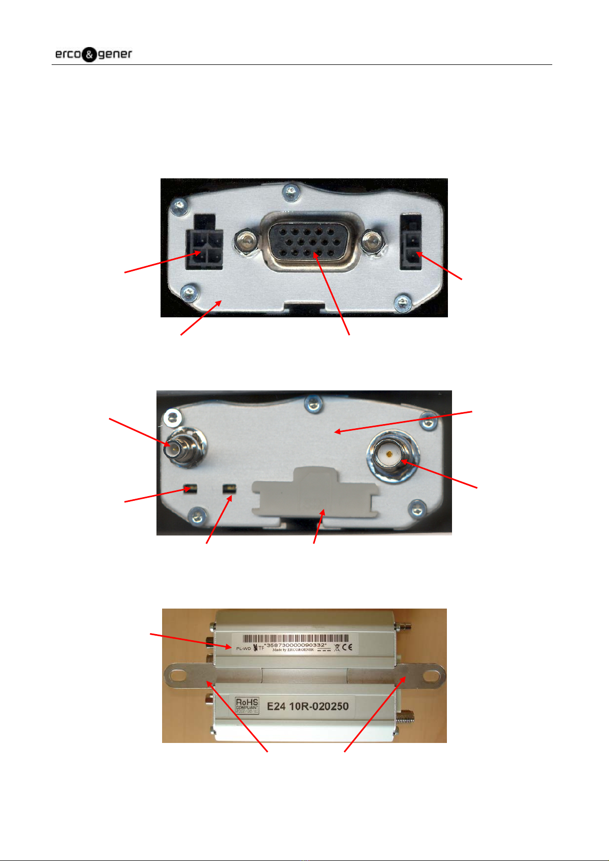
2.3 Modem Labels
Two labels are attached to the underside of the modem:
•A production label provides the following information:
- CE mark,
- Crossed wheelie-bin mark (DEEE standard),
- DC supply (VDC),
- Hardware WD mark,
- Q24PLUS mark (PL),
- The IMEI 15-digit bar code.
•Additional marking: ROHS (2002/95/CE) and "E" (E24 10R-020250).
WARNING : The PL mark on the case label indicates that the GenLoc 31e embedded the new
generation of Wismo Q24PLUS.
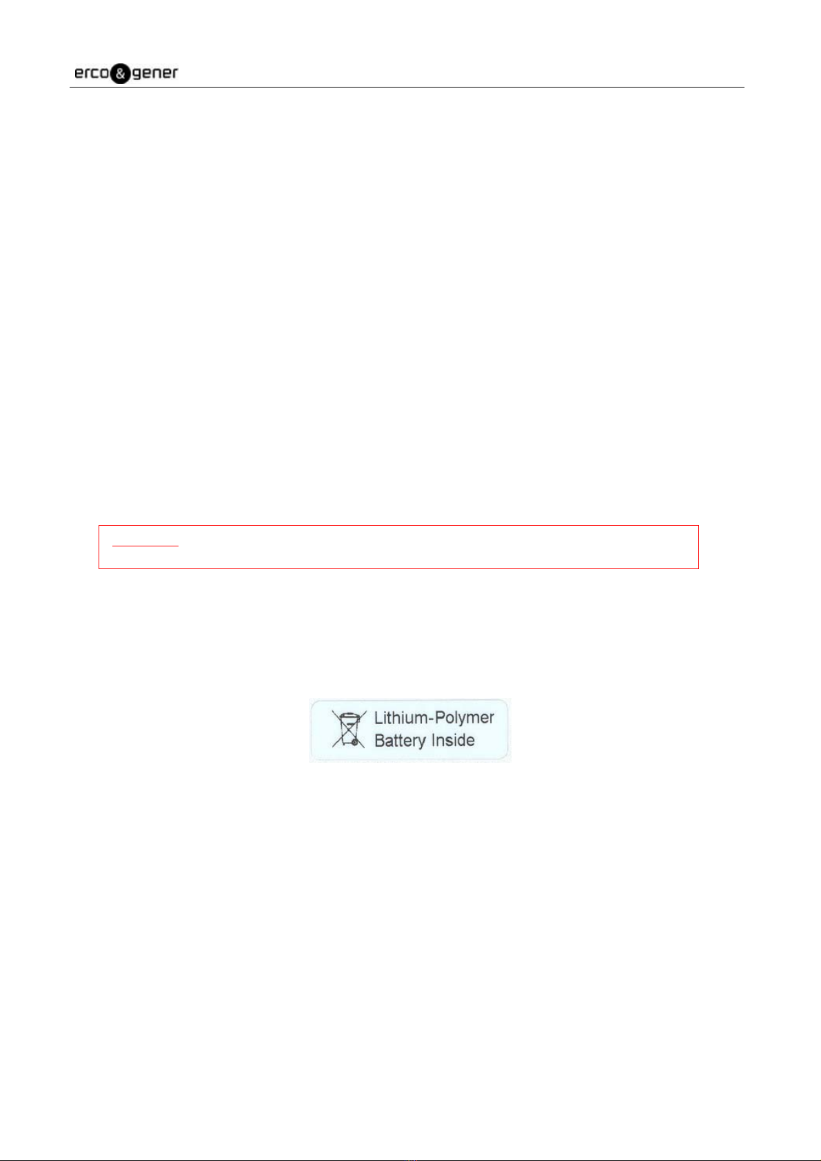
Note : The following label "Lithium-Polymer Battery Inside" may be present on the case if the optional
internal battery has been mounted during production.
EG_GenLoc31e_988_UG_008_UK Page 12 / 60
Descriptions and non-contractual illustrations in this document are given as an indication only.
ERCO&GENER reserves the right to make any modifications.
3 General Presentation
3.1 Physical description
Description of the GenLoc 31e modem:
Two fixing brackets for attaching the modem to a support:
Connector
Micro-Fit 4-pins/M
Front side Connector Sub HD
15-pins/F
Connector
Micro-Fit 2-pins/M
Rear side
Connector SMA/F
(GSM/GPRS antenna)
Connector
SMB/M
(GPS antenna)
GPS LED
GSM LED SIM card cover
Fixing brackets
WatchDog
and
Q24PLUS
Mark

EG_GenLoc31e_988_UG_008_UK Page 13 / 60
Descriptions and non-contractual illustrations in this document are given as an indication only.
ERCO&GENER reserves the right to make any modifications.
3.2 External connections
3.2.1 Connections
3.2.1.1 Antenna connectors
GSM antenna connector:
The GSM antenna connector is a 50Ωimpedance female SMA type.
GPS antenna connector:
The GPS antenna connector is a 50Ωimpedance male SMB type.
3.2.1.2 Micro FIT connectors
4-pin Micro FIT female connector:
This connector allows the connection of an external DC supply, and provides one general-purpose input and
one general-purpose output.
WARNING : Pins 3 and 4 are used by the GPIO’s. It is strictly forbidden to connect a supply voltage to
these pins – the modem may be damaged.
2-Pin Micro FIT female connector:
This connector provides 2 general-purpose inputs.
3.2.1.3 15-pin Sub HD female connector
This connector provides:
- The serial RS232 link,
- The audio line connection (microphone and loud-speaker),
- The BOOT and RESET signals.
Pin N° Signal
1 +VDC
2 GND
3 INPUT 1 (E1)
4 OUTPUT (S1)
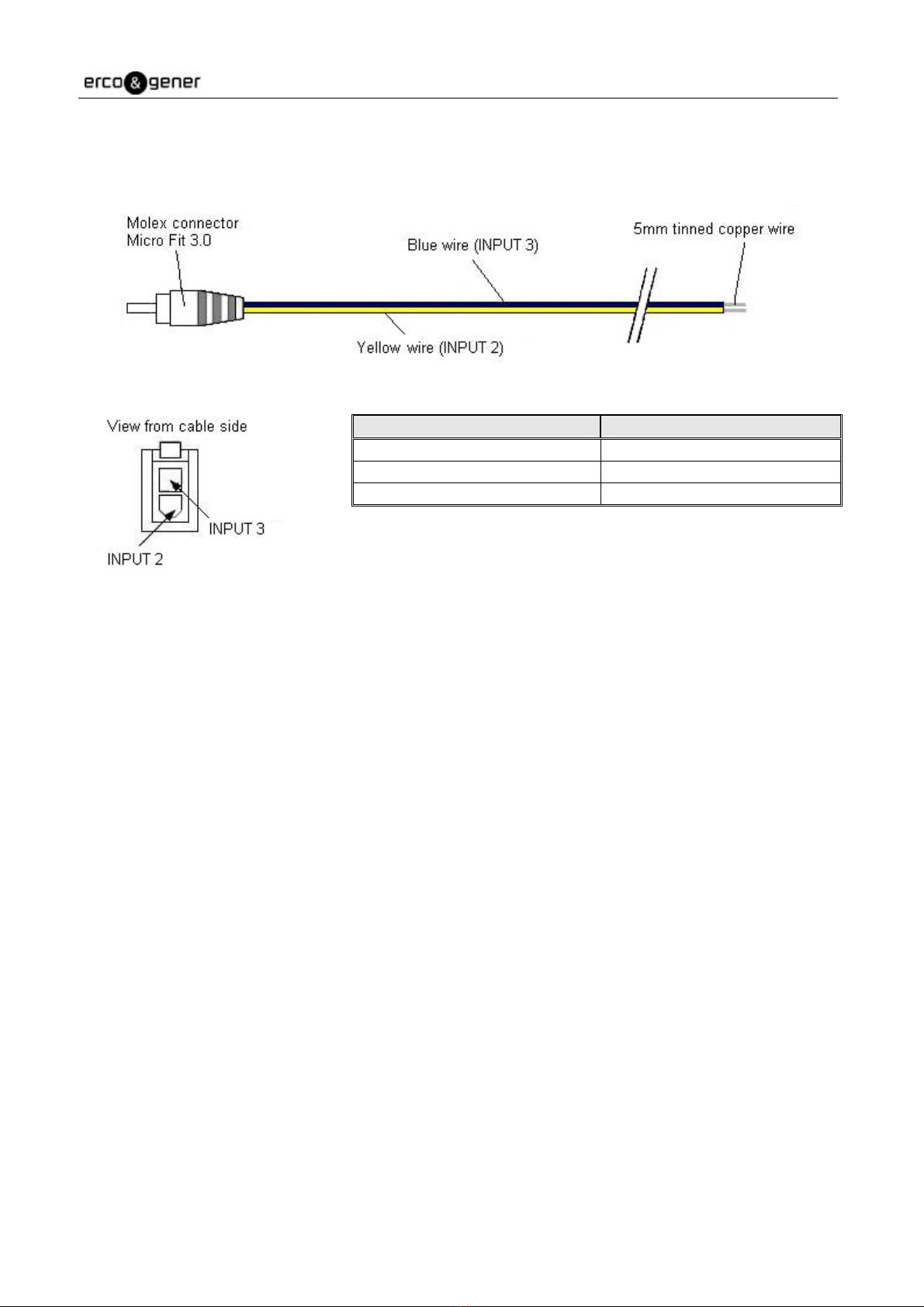
Pin N° Signal
1 INPUT 3 (E3)
2 INPUT 2 (E2)

EG_GenLoc31e_988_UG_008_UK Page 14 / 60
Descriptions and non-contractual illustrations in this document are given as an indication only.
ERCO&GENER reserves the right to make any modifications.
Pin N° Description Circuit (V24 – RS232C) GPS Multiplexing I/O
1 Signal detection / Buzzer 109 – DS – DCD O
2 Data transmission 103 – ED – TXD I
3 Boot BOOT I
4 Microphone + MIC2P I
5 Microphone - MIC2N I
6 Data reception 104 – RD – RXD O
7 Data Set Ready 107 – PDP – DSR NMEA/UBX Frames O
8 Data Terminal Ready 108/2 – TDP – DTR UBX Frames I
9 Ground 102 – TS – GND -
10 Loud Speaker + SPK2P O
11 Clear To Send 106 – PAE – CTS O
12 Request To Send 105 – DPE – RTS I
13 Ring Indicator / 3,8V 125 – IA – RI O
14 Reset RESET I
15 Loud Speaker - SPK2N O
Note (by default):
- Pin 1 is the Buzzer output (connection of 109/DCD circuit optional).
- Pin 13 is a DC output (for powering typically a GenBlue 10eaccessory) of 3,8V 100mA
(connection of 125/RI circuit optional).
3.2.2 Cables
3.2.2.1 4-wire micro FIT
This cable provides power to the modem and access to one general-purpose input and one general-purpose
output.
Component Characteristics
4-pin Micro FIT connector Type : MOLEX
Cable Length ≈1.5m
Wire Tinned copper 24 x 0.2 mm
Surface area : 0.75 mm²
EG_GenLoc31e_988_UG_008_UK Page 15 / 60
Descriptions and non-contractual illustrations in this document are given as an indication only.
ERCO&GENER reserves the right to make any modifications.
3.2.2.2 2-wire micro FIT
This cable provides access to two general-purpose inputs.
Component Characteristics
2-pin Micro FIT connector Type : MOLEX
Cable Length ≈1.5m
Wire Surface area : 0.5 mm²

EG_GenLoc31e_988_UG_008_UK Page 16 / 60
Descriptions and non-contractual illustrations in this document are given as an indication only.
ERCO&GENER reserves the right to make any modifications.
4 Characteristics And Services
The GenLoc 31e is :
•A class 10 GSM/GPRS modem intended for asynchronous binary data transmission, fax Group3
(Class 2), SMS and voice.
•A GPS modem for position tracking.
The modem’s characteristics and available services are summarised in the table below :
Characteristics GSM DCS
Standard Transmission 880 MHz to 915 MHz
Reception 925 MHz to 960 MHz
Conforms to E-GSM
Class 4
Power 2W
Conforms to ETSI GSM/GPRS Phase 2
Transmission 1710 MHz to 1785 MHz
Reception 1805 MHz to 1880 MHz
Class 1
Power 1W
Conforms to ETSI GSM/GPRS Phase 2
GSM Caller Identification
Call forwarding
Conference
Call holding and pick-up
USSD
Forbidden call
GPRS Multi slot Class 10
Class 2 supported
PBCCH supported
CS1 to CS4 coding
TCP/IP Stack PPP RFC, TCP Socket, UDP Socket, SMTP, POP3, FTP
GPS Civil Frequency L1 (1575.42MHz)
16 channel receiver
Precision : 2.5m CEP
Sensitivity : -158dB
Protocols : NMEA-0183, UBX Binary and RTCM input
A-GPS compatible
Interfaces Serial Interface RS232 V24 from 300 to 115200 bauds via 15-pin/F Sub HD
Complete AT command set for GSM/GPRS (07.05 and 07.07)
Specific AT command set for GPS
GPIO’s : 3 opto-coupled inputs and 1 open-collector output
Audio Emergency voice call 112
FR/EFR/HR
Echo cancellation
Noise reduction
Buzzer Output
SMS Text, PDU, MT, MO CB
Data/Fax Asynchronous Data Circuit, transparent and non-transparent 9600 (Standard) to
14400bds (depending on network)
Compatible Fax Group 3
SIM Interface SIM 3V or 1,8V
SIM Tool Kit version 99
Power supply 5.5V to 32V DC
Antennae SMA-F connector the GSM antenna
SMB-M for the GPS antenna
Antenna management GPS active 3V

EG_GenLoc31e_988_UG_008_UK Page 17 / 60
Descriptions and non-contractual illustrations in this document are given as an indication only.
ERCO&GENER reserves the right to make any modifications.
5 Using The Modem
5.1 Starting with the modem
5.1.1 Mounting the modem
To mount the modem on a support, use the fixing brackets as shown in the diagram below:
5.1.2 Installation of the modem
To install the modem, it is recommended to perform the following operations with the modem turned off:
- Remove the SIM card cover on the rear side.
- Carefully insert the SIM card into its holder.
- Verify that the SIM card is positioned correctly.
- Connect the GSM antenna to the SMA connector.
- Connect the GPS antenna to the SMB connector.
- To connect to a DTE, connect the V24 link using the 15-pin Sub HD cable.
- Connect the supply cable to an external regulated DC source (for automobile applications, refer to
chapter 5.2 Recommendations for using the modem in vehicles).
- Connect the supply cable to the modem and turn on the power supply. The GSM LED will light up.
The modem is now ready. Refer to chapter 5.10 Main AT commands (HAYES) for a description of
the commands for configuring and using the modem.
Note :
- Must be fixed to a flat
surface.
- Maximum height of the
screw head height: 2 mm

EG_GenLoc31e_988_UG_008_UK Page 18 / 60
Descriptions and non-contractual illustrations in this document are given as an indication only.
ERCO&GENER reserves the right to make any modifications.
5.1.3 Communication with the modem
Connect the RS232 cable between the DTE (the COM port) and the modem (DCE).
Configure the DTE RS232 port as follows :
▪Data rate : 9600 bps,
▪Data size : 8 bits,
▪Parity : None,
▪Stop bits : 1,
▪Flow control : hardware.
Via the DTE (a PC running a communications application such as HyperTerminal), enter the command
AT(CR). The modem should reply with OK.
In the case where no communication can be established with the modem :
▪Verify the RS232 connexion between the DTE and the modem (DCE),
▪Verify the configuration of the COM port on the DTE.
Some examples of AT commands which can be sent to the modem once the communication has been
established and verified (these commands are explained in detail later in the document) :
▪AT+CGSN : the modem should reply with a 15 digit number (beginning with "35873000xxxxxxx").
▪AT+CPIN=xxxx : enter the code of the SIM card xxxx (if active).
▪AT+CSQ : verify the GSM signal reception level.
▪AT+CREG ? : verify the registration of the modem on the network.
▪ATD<telephone number> : start a voice call.
▪ATH : hang-up (end of the call).
▪AT+WGPSPOS : retrieve the current GPS position.
For further information about these AT commands and their associated parameters, refer to the "AT
Commands Interface Guide" from WAVECOM and the "Commands List" from 'ERCO&GENER.
5.1.4 Checking the "LLC" application
To be able to access the GPS module an to read/write the GPIOs, the GenLoc 31e executes a specific
loaded application called "LLC" or "LLC T".
The application "LLC T" includes all the functions of the "LLC" and also includes the functions FTP / TCP /
SNTP.
The presence of one of these application may be checked via the command ATI8 after having activated it via
the command +WOPEN=1. (refer to the "Commands List" from ERCO&GENER.)
EG_GenLoc31e_988_UG_008_UK Page 19 / 60
Descriptions and non-contractual illustrations in this document are given as an indication only.
ERCO&GENER reserves the right to make any modifications.
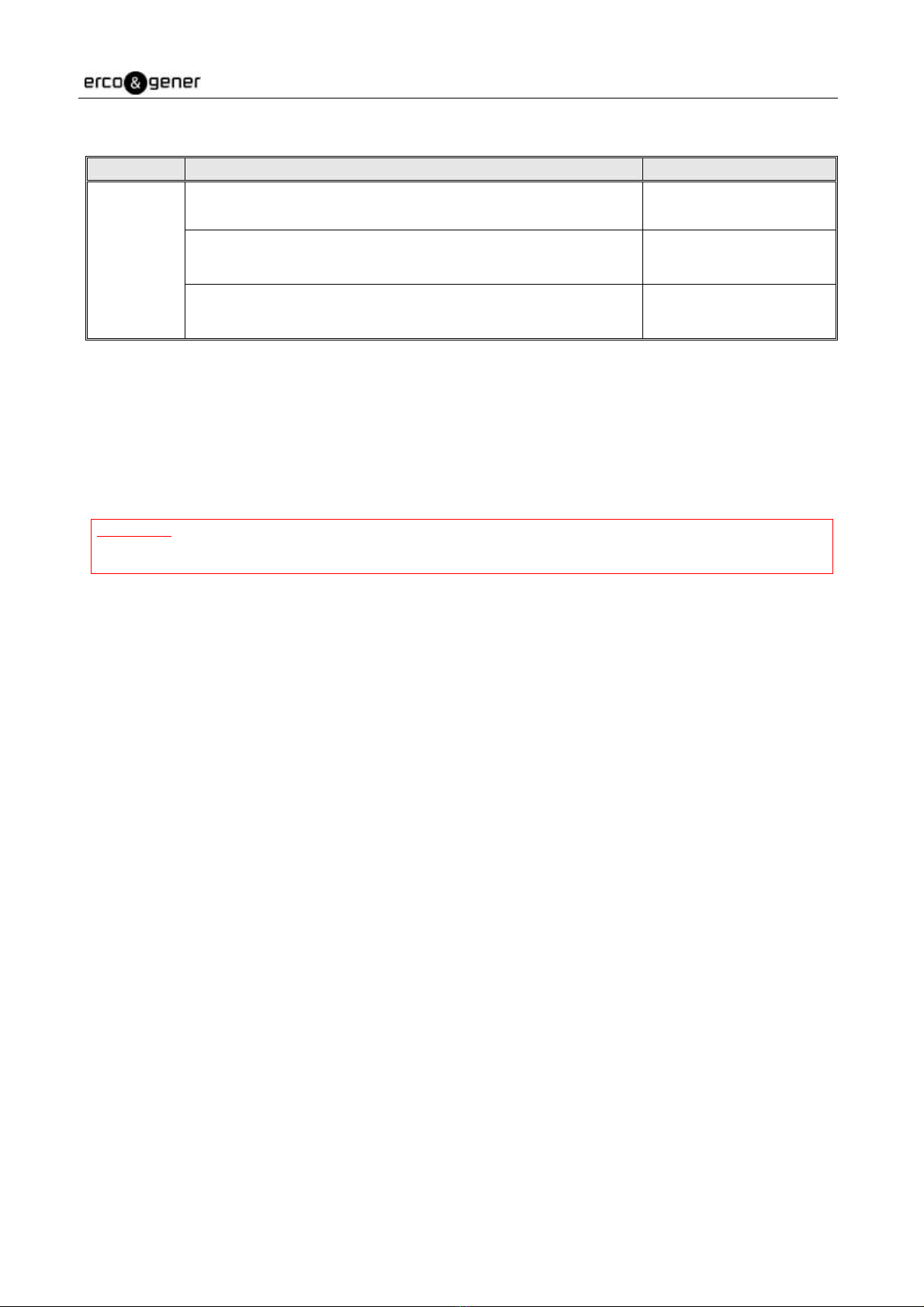
The table below indicates the main responses by the modem:
5.1.4 Re-initialisation of the modem
The hardware RESET signal is available on pin 14 of the 15-pin Sub HD connector. The modem is re-
initialised when this RESET signal is held at a low level for at least 500µs.
WARNING : This RESET signal should be considered as a means of re-initialising the modem in cases of
emergency only. For further details concerning the RESET of the modem, see the chapter
7.6 RESET.
Command Response Interpretation
OK No application has been
loaded and/or activated
LLC V1.14 GenLoc31e - Q24PL B OAT313 - Jun ... 13:53:01
OK
The application loaded
and activated is LLC
V1.14
ATI8
LLC T V1.04 GenLoc31e - Q24PL B OAT314 - Jul ... 11:30:16
OK
The application loaded
and activated is LLC T
V1.04
EG_GenLoc31e_988_UG_008_UK Page 20 / 60
Descriptions and non-contractual illustrations in this document are given as an indication only.
ERCO&GENER reserves the right to make any modifications.
5.2 Recommendations for using the modem in vehicles
WARNING : The power supply connector on the GenLoc 31e must NOT be connected directly to the
battery of a vehicle.
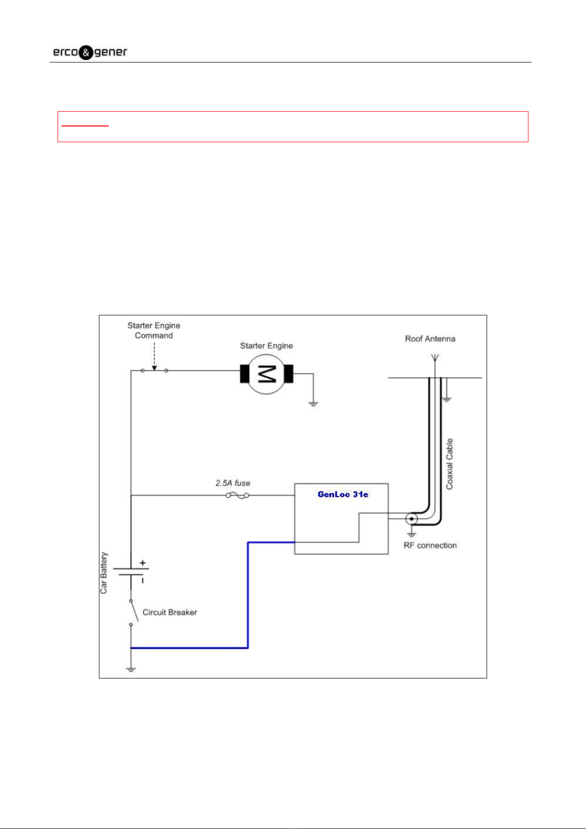
5.2.1 Recommended connection to the battery in a lorry
All lorries have a circuit breaker outside the cabin. The circuit breaker is necessary for security reasons. For
example, if a fire breaks out in the lorry’s electric box, the driver may cut the power source to avoid further
danger and damage (explosion).
The circuit breaker is connected to the ground of the lorry, usually connected to the fuse box. As such, most
lorry circuit breakers cut the ground connexion rather than the battery power side as shown in the diagram
below :
The diagram above shows a recommended connexion, where the modem is connected after the circuit
breaker to the ground of the lorry (or in the fuse box) and NOT directly to the earth of the battery
Other manuals for Genloc 31e
1
Table of contents
Other Erco&Gener Modem manuals

Erco&Gener
Erco&Gener GenPro 53e User manual

Erco&Gener
Erco&Gener GenPro 325e User manual

Erco&Gener
Erco&Gener Genloc 31e Installation manual

Erco&Gener
Erco&Gener GenPro 20e User manual

Erco&Gener
Erco&Gener GENPRO 40E R2 User manual

Erco&Gener
Erco&Gener GenPro 18e User manual

Erco&Gener
Erco&Gener GenPro 15e User manual

Erco&Gener
Erco&Gener GenPac 92c User manual

Erco&Gener
Erco&Gener GenLoc 31e AOB User manual

Erco&Gener
Erco&Gener GENLoc25 User manual


