Erco&Gener GenLoc 31e AOB User manual
L’esprit Modem
User Guide
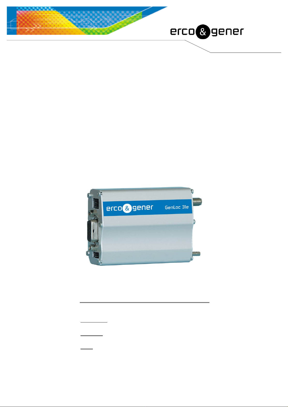
GenLoc 31e AOB
Reference : EG_GenLoc31e_AOB_1003_UG_006_UK
Revision : 006
Date : 04/07/2011
S.A. ERCO & GENER – ZI de St. Lambert-des-Levées – BP 30163 – F-49412 SAUMUR Cedex
Tél. : +33 (0)2 41 83 13 00 – Fax : +33 (0)2 41 67 19 20 – www.ercogener.com – infos@ercogener.com
SA CAPITAL 200873 €– R.C. SAUMUR B 332 174 820 – SIRET 332 174 820 00032 – NAF 2630Z – TVA Intra : FR 16 332 174 820
EG_GenLoc31e_AOB_1003_UG_006_UK Page 2 / 64
Descriptions and non-contractual illustrations in this document are given as an indication only.
ERCO&GENER reserves the right to make any modifications.
Document History
Revision Modifications Author Date
000 CREATION F. LE BRETON 30/10/08
001 - Updating of the section WARNINGS
- Precision about the verification of the modem
- Precision about the turning off of the equipment
- Synoptic of GenLoc 31e AOB architecture
- Synoptic of EGM architecture
- Updating of consumptions
- Adding information about characteristics of the loudspeaker
- Updating of the TOR inputs and outputs
- Adding of the bus One Wire
- Adding GPS consumptions
- Adding consumption of battery option
- Updating of the GPS characteristics
- Adding of the accelerometer characteristics
SDU
YST
17/05/10
002 Does not exist. Change directly to Rev. 003 for synchronization
with the French revision.
YST
003 - Precision of the table of § 8.2.3.1 Opto-coupled Inputs-
- Addition of § 8.2.9 Characteristics of the RS232 serial link
(UART))
- Addition of § 7.3.4 Sortie +3.8V
- Change spare battery by back-up battery
- Change lorry by truck
- Updating Normalized signals of a RS232 serial link
- Updating example of AT+GPIOGET
- updating § 7.11.2 EGM Architecture
- Adding symbols
-Decomposition of chapter 8.2.2.1
YST 12/08/10
004 Updating
- of the limit of use of the digital input du § 8.2.3.1 Opto-coupled
Inputs
- of the environmental conditions for the use with battery option. §
8.3 Environmental characteristics
- of the information concerning the certifications § 8.4
Standards/Conformities
- the non-guarantee of the battery § 9.3 Care and maintenance
- the certificate of conformity.
EFO
YST 27/01/11
005 Add 4-wire cable with mini Blade fuse
§ 2.1 Contents and § 3.2.2.1 4-wire micro FIT
Updating
- of the environmental conditions for the use with battery option. §
8.3 Environmental characteristics
- § 3.2.1.2 Micro FIT connectors Pin 2 is an INPUT, not OUTPUT
YST 14/03/11
006
Updating limits of
- § 8.2.2.3 Buzzer
- § 8.2.3.2 Output
- § 8.2.3.3 Analog input
With battery option, prepare the modem for storage or transport
conditions see
§ 5.10 Turning off the modem
§ 7.2.2 Internal battery option
§8.2.1 Power supply
YST 04/07/11
The main modifications of this document compared to the previous version are easily identifiable on the
screen by the blue color of the text.

EG_GenLoc31e_AOB_1003_UG_006_UK Page 3 / 64
Descriptions and non-contractual illustrations in this document are given as an indication only.
ERCO&GENER reserves the right to make any modifications.
TABLE OF CONTENTS
GENLOC 31E AOB .............................................................................................................................................. 1
PRESENTATION............................................................................................................................................... 6
WARNING ......................................................................................................................................................... 7
COPYRIGHT ..................................................................................................................................................... 8
1 REFERENCES ............................................................................................................................................... 9
1.1 REFERRED DOCUMENTS ................................................................................................................................. 9
1.2 ABBREVIATIONS ............................................................................................................................................. 9
1.3 SYMBOLS..................................................................................................................................................... 11
2 PACKAGING................................................................................................................................................ 11
2.1 CONTENT..................................................................................................................................................... 11
2.2 PACKING CASE ............................................................................................................................................. 12
2.3 MODEM LABELS............................................................................................................................................ 12
3 GENERAL PRESENTATION....................................................................................................................... 13
3.1 DESCRIPTION............................................................................................................................................... 13
3.2 EXTERNAL CONNECTIONS ............................................................................................................................. 14
3.2.1 Connections ................................................................................................................................... 14
3.2.1.1 Antenna connectors................................................................................................................ 14
3.2.1.2 Micro FIT connectors.............................................................................................................. 14
3.2.1.3 15-pin Sub D HD connector.................................................................................................... 14
3.2.2 Cables............................................................................................................................................ 15
3.2.2.1 4-wire micro FIT cable ............................................................................................................ 15
3.2.2.2 2-wire micro FIT cable ............................................................................................................ 16
4 CHARACTERISTICS AND SERVICES ....................................................................................................... 17
5 USING THE MODEM ................................................................................................................................... 19
5.1 STARTING WITH THE MODEM ......................................................................................................................... 19
5.1.1 Mounting the modem ..................................................................................................................... 19
5.1. Installation of the modem................................................................................................................. 19
5.1.3 Checking the communication with the modem .............................................................................. 20
5.1.3.1 Without Library ....................................................................................................................... 20
5.1.3.2 Standard with EGM Library .................................................................................................... 21
5.1.3.3 The application ERCO & GENER EaseLoc-01 ...................................................................... 21
5.1.3.4 The owner application ............................................................................................................ 21
5.1.4 SIM card Extraction........................................................................................................................ 21
5.1.5 Hardware reset of the modem ....................................................................................................... 22
5.2 SPECIFIC RECOMMENDATIONS FOR THE USE OF THE MODEM IN VEHICLES ........................................................ 23
5.2.1 Recommended Connection on the battery of a truck .................................................................... 23
5.2.2 Technical constraints in truck......................................................................................................... 24
5.3.1 GSM led ......................................................................................................................................... 25
5.3.1.1 Without library......................................................................................................................... 25
5.3.1.2 With EGM standard library ..................................................................................................... 25
5.3.1.3 The application ERCO & GENER EaseLoc-01 ...................................................................... 25
5.3.1.4 The owner application ............................................................................................................ 25
5.3.2 GPS led.......................................................................................................................................... 25
5.4 ECHO FUNCTION OF THE DEACTIVATED AT COMMANDS .................................................................................. 25
5.5 CHECKING THE QUALITY OF THE GSM RECEPTION SIGNAL .............................................................................. 26
5.6 VERIFICATION OF THE PIN CODE ................................................................................................................... 27
5.7 VERIFICATION OF THE MODEM REGISTRATION ON THE GSM NETWORK ............................................................ 27
5.8 READING A CURRENT POSITION GIVEN BY THE GPS ....................................................................................... 28
5.9 MAIN AT COMMANDS (HAYES) .................................................................................................................... 29
5.10 TURNING OFF THE MODEM .......................................................................................................................... 30
5.11 MODEM UPDATING PROCEDURE .................................................................................................................. 31

EG_GenLoc31e_AOB_1003_UG_006_UK Page 4 / 64
Descriptions and non-contractual illustrations in this document are given as an indication only.
ERCO&GENER reserves the right to make any modifications.
6 TROUBLE SHOOTING ................................................................................................................................ 32
6.1 PROBLEM OF COMMUNICATION BETWEEN THE MODEM AND THE RS232 LINK (V24).......................................... 32
6.2 "ERROR" MESSAGE .................................................................................................................................... 33
6.3 "NO CARRIER" MESSAGE ........................................................................................................................... 33
7 FUNCTIONAL DESCRIPTION..................................................................................................................... 35
7.1 ARCHITECTURE ............................................................................................................................................ 35
7.2 POWER SUPPLY ........................................................................................................................................... 35
7.2.1 General presentation ..................................................................................................................... 35
7.2.2 Internal battery option .................................................................................................................... 36
7.2.2.1 Presentation of internal battery option.................................................................................... 36
7.2.2.2 Specifications of the internal battery option............................................................................ 36
7.2.2.3 Charge voltage and supply voltage ........................................................................................ 37
7.2.2.4 Indication of presence/absence of the external power supply ............................................... 37
7.2.2.5 Instruction and restrictions of use........................................................................................... 38
7.2.3 Protections of the power supply..................................................................................................... 38
7.3 RS232 SERIAL LINK...................................................................................................................................... 38
7.3.1 General Presentation ..................................................................................................................... 38
7.3.2 Pins description.............................................................................................................................. 39
7.3.4 Output +3.8V.................................................................................................................................. 40
7.4 INPUTS/OUTPUTS FUNCTIONING .................................................................................................................... 40
7.5 BOOT......................................................................................................................................................... 41
7.6 RESET ....................................................................................................................................................... 41
7.6.1 General presentation ..................................................................................................................... 41
7.6.2 RESET sequence .......................................................................................................................... 42
7.7 WATCHDOG................................................................................................................................................. 42
7.8 AUDIO ......................................................................................................................................................... 43
7.8.1 Microphone inputs.......................................................................................................................... 43
7.8.2 Loud-speaker outputs (Speaker) ................................................................................................... 44
7.8.3 Buzzer outputs ............................................................................................................................... 44
7.9 DIRECT GPS MODE (ANALOGICAL SWITCH)................................................................................................... 44
7.10 GPS MODULE ............................................................................................................................................ 45
7.11 INTERNAL PROCESSOR ............................................................................................................................... 45
7.11.1 EGM presentation ........................................................................................................................ 45
7.11.2 EGM Architecture......................................................................................................................... 46
8 TECHNICAL CHARACTERISTICS ............................................................................................................. 47
8.1 MECHANICAL CHARACTERISTICS ................................................................................................................... 47
8.2 ELECTRICAL CHARACTERISTICS..................................................................................................................... 48
8.2.1 Power supply ................................................................................................................................. 48
8.2.2 Audio interface ............................................................................................................................... 51
8.2.2.1 Microphone ............................................................................................................................. 51
8.2.2.2 Loudspeaker........................................................................................................................... 51
8.2.2.3 Buzzer..................................................................................................................................... 52
8.2.3 Inputs/Output ................................................................................................................................. 53
8.2.3.1 Opto-coupled Inputs ............................................................................................................... 53
8.2.3.2 Output ..................................................................................................................................... 54
8.2.3.3 Analog input............................................................................................................................ 55
8.2.3.4 Bus One Wire ......................................................................................................................... 55
8.2.4 SIM interface.................................................................................................................................. 56
8.2.5 RESET signal................................................................................................................................. 56
8.2.6 RF GSM/DCS characteristics ........................................................................................................ 56
8.2.6.1 RF functioning ........................................................................................................................ 56
8.2.6.2 GSM external antenna............................................................................................................ 57
8.2.7 GPS characteristics ....................................................................................................................... 57
8.2.7.1 GPS functioning...................................................................................................................... 57
8.2.7.2 GPS external antenna ............................................................................................................ 58
8.2.7.3 Installation of the GPS external antenna................................................................................ 58
8.2.8 Characteristics of the accelerometer ............................................................................................. 58
8.2.9 Characteristics of the RS232 serial link (UART)............................................................................ 59
8.3 ENVIRONMENTAL CHARACTERISTICS.............................................................................................................. 59
8.4 STANDARDS/CONFORMITIES ......................................................................................................................... 60

EG_GenLoc31e_AOB_1003_UG_006_UK Page 5 / 64
Descriptions and non-contractual illustrations in this document are given as an indication only.
ERCO&GENER reserves the right to make any modifications.
9 SECURITY RECOMMENDATIONS............................................................................................................. 61
9.1 GENERAL SECURITY ..................................................................................................................................... 61
9.2 SECURITY IN A VEHICLE ................................................................................................................................ 62
9.3 CARE AND MAINTENANCE.............................................................................................................................. 62
9.4 YOUR RESPONSIBILITY.................................................................................................................................. 62
10 RECOMMENDED ACCESSORIES ........................................................................................................... 63
11 CLIENT SUPPORT .................................................................................................................................... 63
DECLARATION OF CONFORMITY ............................................................................................................... 64

EG_GenLoc31e_AOB_1003_UG_006_UK Page 6 / 64
Descriptions and non-contractual illustrations in this document are given as an indication only.
ERCO&GENER reserves the right to make any modifications.
Presentation
Entirely dedicated to geo-localization and embedded data services, the modem GenLoc 31e AOB combines
both GSM/GPRS and GPS functions in the same robust case.
The GPS data can be transmitted by SMS or data GSM/GPRS communication.
This product includes the GPS function 50 channels Hypersense and its sensitivity ensures the GPS data
collection in difficult environmental conditions.
The modem is Quad-Bands 850/900/1800/1900 MHz and GSM/GPRS Class 10.
The GenLoc 31e AOB has 3 operating modes:
External mode (standard): The driving is made by an external application. The modem is used with
the AT commands set (see EG_EGM_CL_xxx_yy of ERCO & GENER).
Autonomous mode (optional): Once configured, the modem is autonomous; it cyclically registers the
positions and transmits them automatically to the client’s application via different services: SMS,
GSM Data, TCP socket GPRS (see EG_EaseLoc_01_CL_xxx_yy of ERCO & GENER).
Specific development mode: the EGM development tool allows to develop personalized embedded
application. For more information concerning the tools and the training, please contact our sales
department.
The GenLoc 31e AOB provides TOR inputs/outputs allowing the creation of embedded telematic solutions
with high added value.
This document describes the modem and provides the following information:
- General presentation,
- Functional description,
- Available basic services,
- Installation and use of the modem (first level),
- Trouble shooting,
- Recommended accessories for the use of the modem.
For more information concerning this document, ERCO & GENER puts at your disposal the following
elements:
- Commands List
External mode EG_EGM_CL_xxx_yy
Autonomous mode EG_EaseLoc_01_xxx_yy
- Application Note EG_GenLoc31e_1003_AN_xxx_yy
- Release Note EG_GenLoc31e_1003_RL_xxx_yy
- Client support (Hot-Line)

EG_GenLoc31e_AOB_1003_UG_006_UK Page 7 / 64
Descriptions and non-contractual illustrations in this document are given as an indication only.
ERCO&GENER reserves the right to make any modifications.
Warning
•Erco&Gener advises to read carefully all the documents concerning the GenLoc 31e AOB (User
Guide, Application Notes, Command List).
•ERCO & GENER cannot be held responsible for:
- The problems due to an inappropriate use of the GenLoc 31e AOB.
- The problems due to a wrong configuration
- The problems due to a wrong use of an embedded software application developed or
supplied by a third party.
- The dysfunctions due to the absence or a bad coverage of the GSM, GPRS and GPS
networks.
- The dysfunctions if the product is used for the watching of physical persons where human
life is engaged.
•ERCO & GENER reserves the right to modify the functions of its products "GenLoc 31e AOB" and
"EaseLoc" without previous notice.
- In order to avoid any risk of electrocution, do not open the casing.
- For any functioning, the casing must be closed.
- No internal part can be repaired by the user. The GenLoc 31e AOB must be returned to the factory for any
repair.
- The GenLoc 31e AOB must be placed in a normally ventilated area, out of sources of heat.
- In order to guarantee the electromagnetic compatibility, the length of the serial cable, the supply cable and
the inputs/outputs cable must not exceed 3 meters.
- The GenLoc 31e AOB must not be connected directly to the mains supply; a voltage adapter must be
used.
SCRAP THE WORN BATTERIES ACCORDING TO INSTRUCTIONS;

EG_GenLoc31e_AOB_1003_UG_006_UK Page 8 / 64
Descriptions and non-contractual illustrations in this document are given as an indication only.
ERCO&GENER reserves the right to make any modifications.
Copyright
The reproduction, transfer, distribution or storage of part or the totality of the contents of this document, in
any form, without the prior written authorization of ERCO & GENER is strictly prohibited.
GenLoc 31e AOB is a trademark of ERCO & GENER.
Hayes is a registered trademark of Hayes Microcomputer Product Inc. The names of products and
companies mentioned in this document may be names or trademarks of their respective holders.
The use of some products or services described in this document may require a paying subscription. The
availability of some products or services described in this document may change, depending on the
configurations and the materials.
In some countries, restrictions of use of the devices may be applied. For more information, thank you to
contact your nearest legally qualified local government representative.
ERCO & GENER follows a method of continuous development. Consequently, ERCO & GENER reserves
the right to change and improve any of its products described in this document, without notice.
The contents of this document are provided “as it is”. Except for the applicable obligatory laws, no guarantee
in any form, explicit or implicit, including but without being limited to it the implicit guarantees of aptitude to
marketing and of appropriateness to a particular use, is granted concerning the precision, the liability or the
contents of this document. ERCO & GENER reserves the right to revise or withdraw this document at any
time and without notice.
ERCO & GENER cannot be held responsible for any loss of data or income, as well as particular damage,
incidental, consecutive or indirect.

EG_GenLoc31e_AOB_1003_UG_006_UK Page 9 / 64
Descriptions and non-contractual illustrations in this document are given as an indication only.
ERCO&GENER reserves the right to make any modifications.
1 References
1.1 Referred documents
Commands List of
Standard library of ERCO & GENER: EG_EGM_CL_xxx_yy
the embedded application EaseLoc of ERCO & GENER: EG_EaseLoc_01_CL_xxx_yy
Application Notes GenLoc 31e AOB of ERCO & GENER :
EG_Genloc31e_1003_AN_xxx_yy
GSM reference documents:
GSM 07.05.
GSM 07.07.
1.2 Abbreviations
Abbreviations Definition
AC Alternative Current
ACM Accumulated Call Meter
AMR Adaptive Multi-Rate
AT Attention (prefix for modem commands)
BTS Base Transceiver Station
CLK ClocK
CMOS Complementary Metal Oxide Semiconductor
CS Coding Scheme
CTS Clear To Send
dB Decibel
dBc Decibel relative to the Carrier power
dBi Decibel relative to an Isotropic radiator
dBm Decibel relative to one milliwatt
DC Direct Current
DCD Data Carrier Detect
DCE Data Communication Equipment
DCS Digital Cellular System
DSR Data Set Ready
DTE Data Terminal Equipment
DTMF Dual Tone Multi-Frequency
DTR Data Terminal Ready
EEPROM Electrically Erasable Programmable Read-Only Memory
EFR Enhanced Full Rate
EGM Erco Gener Middleware
E-GSM Extended GSM
EMC ElectroMagnetic Compatibility
EMI ElectroMagnetic Interference
ESD ElectroStatic Discharges
ETSI European Telecommunications Standards Institute
FIT Series of connectors (micro-FIT)
FR Full Rate
FTA Full Type Approval
FTP File Transfert Protocol

EG_GenLoc31e_AOB_1003_UG_006_UK Page 10 / 64
Descriptions and non-contractual illustrations in this document are given as an indication only.
ERCO&GENER reserves the right to make any modifications.
GCF Global Certification Forum
GND GrouND
GPIO General Purpose Input Output
GPRS General Packet Radio Service
GPS Global Positioning System
GSM Global System for Mobile communications
HR Half Rate
I Input
IEC International Electrotechnical Commission
IMEI International Mobile Equipment Identification
I/O Input / Output
LED Light Emitting Diode
LLC Low Level Command
MAX MAXimum
ME Mobile Equipment
MIC MICrophone
Micro FIT Family of connectors from Molex
MIN MINimum
MNP Microcom Networking Protocol
MO Mobile Originated
MS Mobile Station
MT Mobile Terminated
NOM NOMinal
O Output
Pa Pascal (for speaker sound pressure measurements)
PBCCH Packet Broadcast Control Channel
PC Personal Computer
PCL Power Control Level
PDP Packet Data Protocol
PIN Personal Identity Number
PLMN Public Land Mobile Network
PUK Personal Unblocking Key
RF Radio Frequency
RFI Radio Frequency Interference
RI Ring Indicator
RMS Root Mean Square
RTS Request To Send
RX Receive
SIM Subscriber Identification Module
SMA SubMiniature version A RF connector
SMB SubMiniature version B RF connector
SMS Short Message Service
SNR Signal-to-Noise Ratio
SNTP Simple Network Time Protocol
SPI Serial Peripheral Interface
SPL Sound Pressure Level
SPK SpeaKer
SRAM Static RAM
TCP/IP Transmission Control Protocol / Internet Protocol
TDMA Time Division Multiple Access
TU Typical Urban fading profile
TUHigh Typical Urban, High speed fading profile
TX Transmit
TYP TYPical
UTC Universal Time Clock
VSWR Voltage Stationary Wave Ratio
EG_GenLoc31e_AOB_1003_UG_006_UK Page 11 / 64
Descriptions and non-contractual illustrations in this document are given as an indication only.
ERCO&GENER reserves the right to make any modifications.
1.3 Symbols
The following symbols are used to highlight the important information of this userguide.
A symbol for the essential information concerning the module integration and performance.
A warning symbol indicates the actions that could harm or damage the module.
2 Packaging
2.1 Content
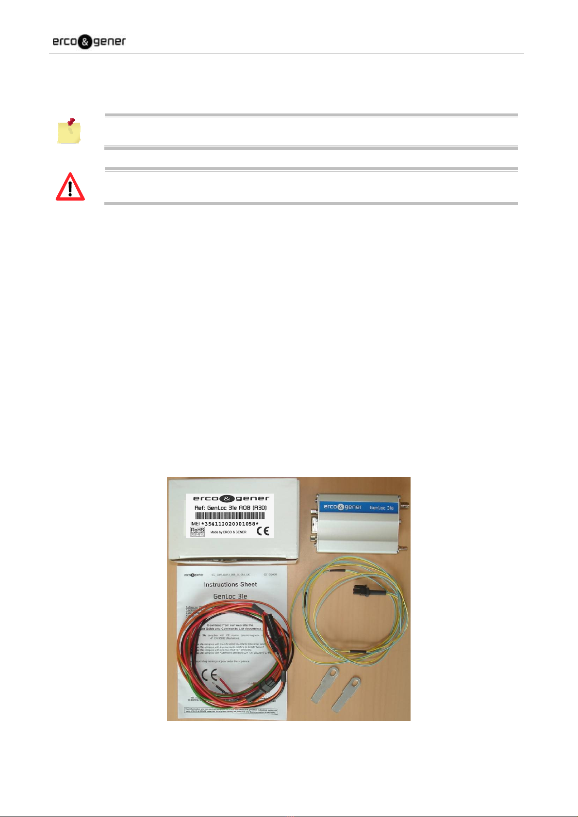
The GenLoc 31e AOB is supplied with:
- a GenLoc 31e AOB cardboard packaging,
- a modem GenLoc 31e AOB,
- 2 fixing brackets,
- a 4-wire cable
Red/Black/Orange/Green stripped with 5x20 fuse
or depending on the supplying
Red/Black/Yellow/Brown stripped with mini Blade fuse of 2A/32V.
- a 2-wire stripped cable (Blue/Yellow).
- A technical sheet (Instructions Sheet).
EG_GenLoc31e_AOB_1003_UG_006_UK Page 12 / 64
Descriptions and non-contractual illustrations in this document are given as an indication only.
ERCO&GENER reserves the right to make any modifications.
2.2 Packing case
The external dimensions of the packing case are:
- Width: 54.5 mm,
- Height: 68 mm,
- Length: 108 mm.
An identification label is put on the top of the packing case. It shows:
- The ERCO & GENER logo,
- The product reference: GenLoc 31e AOB (R30),
- The CE mark,
- The IMEI bar code with 15 digits.
The dimensions of the label are:
- Height: 37 mm,
- Length: 70 mm.
2.3 Modem labels
On the standard casing, there are 2 labels placed on the back part of the modem:
A production label indicating the following information:
- The CE mark,
- The crossed wheelie-bin mark (DEEE standards),
- The direct current mark (VDC),
- The mark AOB (R30),
- The IMEI bar code with 15 digits.
A label of the markings: ROHS (2002/95/CE).
If the internal battery option has been mounted during production, the modem has the
following label: “Lithium-Polymer Battery Inside”.
EG_GenLoc31e_AOB_1003_UG_006_UK Page 13 / 64
Descriptions and non-contractual illustrations in this document are given as an indication only.
ERCO&GENER reserves the right to make any modifications.
3 General Presentation
3.1 Description
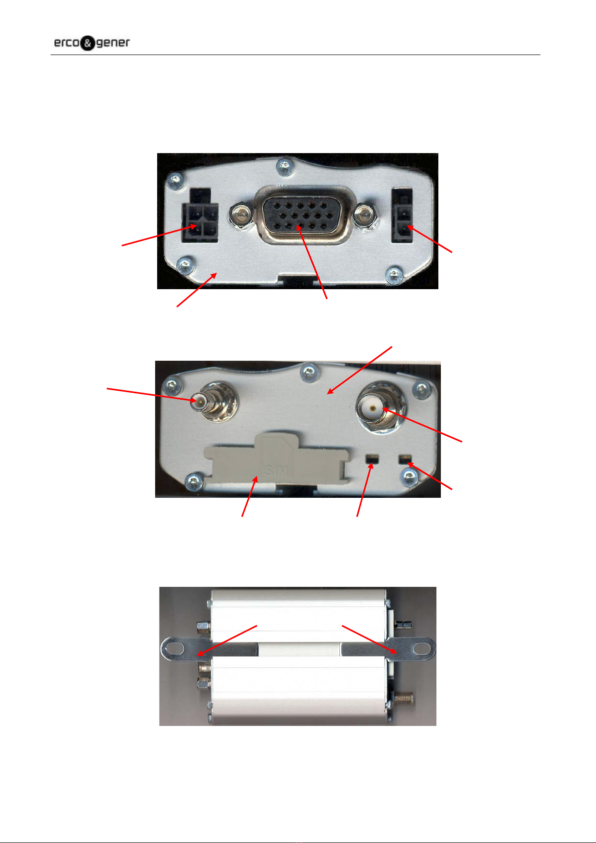
Description of the modem GenLoc 31e AOB:
Micro-Fit 4pin/M
connector
Micro-Fit 2pin/M
Connector
Sub HD 15pin/F
Connector
Front side
Rear side
SMB/M
Connector
SMA/F
Connector
GPS LED
SIM card cover GSM LED
2 brackets to fix the modem on a support.
Fixing brackets
EG_GenLoc31e_AOB_1003_UG_006_UK Page 14 / 64
Descriptions and non-contractual illustrations in this document are given as an indication only.
ERCO&GENER reserves the right to make any modifications.
3.2 External connections
3.2.1 Connections
3.2.1.1 Antenna connectors
GSM antenna connector:
The GSM antenna connector is SMA female with a 50impedance.
GPS antenna connector:
The GPS antenna connector is SMB male with a 50impedance.
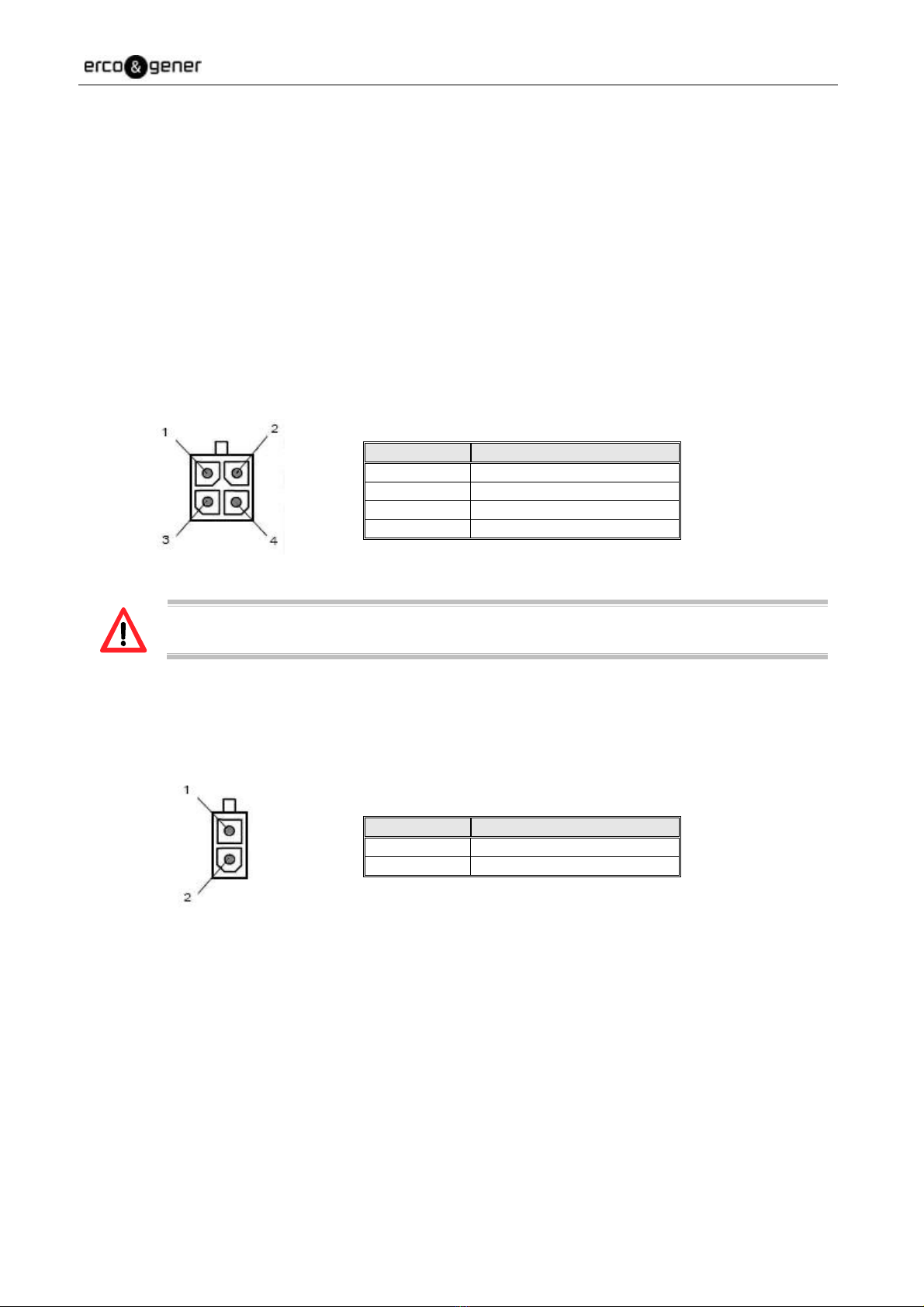
3.2.1.2 Micro FIT connectors
Female Micro FIT Connector with 4 male pins:
This connector is used for the external DC supply and the GPIOs (the 2 signals Input and Output).
Pin N° Signal
1 +VDC
2 GND
3 INPUT 1(E1)
4 OUTPUT (S1)
The pins 3 and 4 are used for the Input/Output functions. The modem can only be powered
by the pins 1 (+VDC) and 2 (GND).
Female Micro FIT connector with 2 male pins:
This connector is used for the GPIO (2 Input signals).
Pin N° Signal
1 INPUT 3 (E3)
2 INPUT 2 (E2) *
* as an option, E2 can be an analog input (contact us)
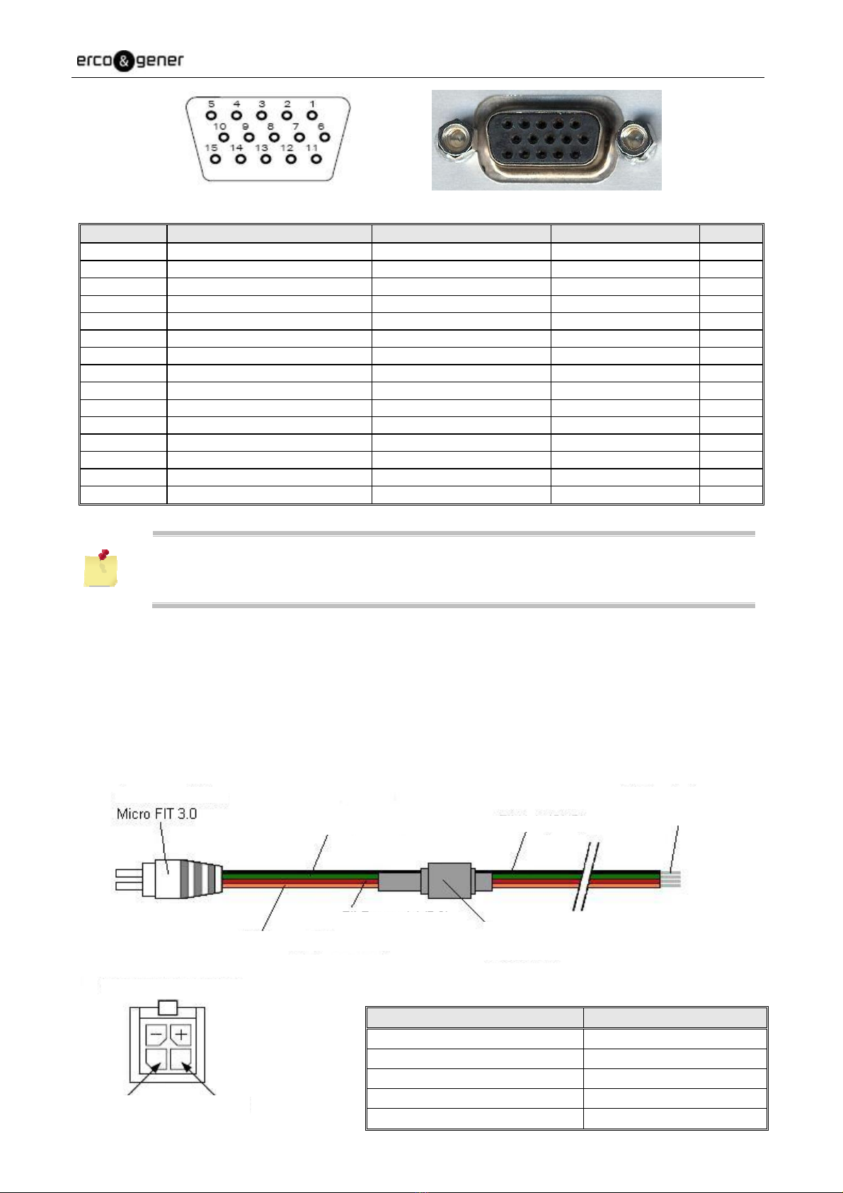
3.2.1.3 15-pin Sub D HD connector
The female 15-pin high density Sub D connector is used for:
- The RS232 serial link connection,
- The audio line connection (microphone and loud-speaker),
- The BOOT and RESET signals.
EG_GenLoc31e_AOB_1003_UG_006_UK Page 15 / 64
Descriptions and non-contractual illustrations in this document are given as an indication only.
ERCO&GENER reserves the right to make any modifications.
Pin N° Description Circuit (V24 – RS232C) GPS Multiplexing I/O
1 Signal detection / Buzzer * 109 – DS – DCD O
2 Data emission 103 – ED – TXD I
3 Boot BOOT I
4 Microphone + MICP I
5 Microphone - MICN I
6 Data reception 104 – RD – RXD O
7 Data set ready 107 – PDP – DSR NMEA/UBX Frames O
8 Data Terminal Ready 108/2 – TDP – DTR UBX Frames I
9 Signalization ground 102 – TS – GND -
10 Loudspeaker + SPKP O
11 Clear to send 106 – PAE – CTS O
12 Request To Send 105 – DPE – RTS I
13 Ring indicator / 3,8V * 125 – IA – RI O
14 Reset RESET I
15 Loud Speaker - SPKN O
(*)Note (by default:
- The pin 1 is the Buzzer output (wiring of the output 109/DCD optional).
- The pin 13 is a fixed tension (to power accessories like GenBlue 15e) of 3,8V 100mA
(wiring of the output 125/RI optional).
3.2.2 Cables
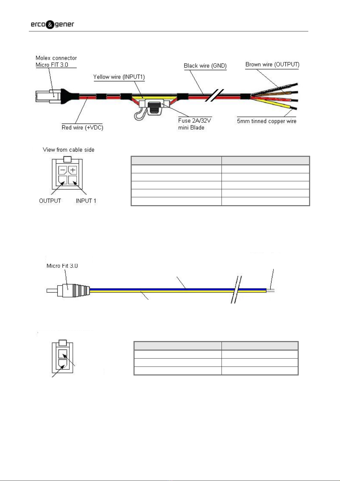
3.2.2.1 4-wire micro FIT cable
One of the two following cables is provided
The 4-wire micro FIT cable allows to power the modem and to use the 2 signals Input and Output.
Component Characteristics
4-pin Micro FIT connector Supplier : MOLEX
Cable Length 1.5m
Wire Tinned copper 24 x 0.2 mm
Section : 0.75 mm²
Fuse F2.5A L250V
Molex connector
Green wire (OUTPUT) Black wire
(
GND
)
5mm tinned copper wire
Red wire (+VDC)
Orange wire (INPUT 1) Fuse 2.5A/250V
(5 x 20 mm)
View from cable side
OUTPUT INPUT 1
EG_GenLoc31e_AOB_1003_UG_006_UK Page 16 / 64
Descriptions and non-contractual illustrations in this document are given as an indication only.
ERCO&GENER reserves the right to make any modifications.
Component Characteristics
4-pin Micro FIT connector
Cable Length 1.5m
Wire Tinned copper 24 x 0.2 mm
Surface area : 0.75 mm²
Fuse mini N 2A 32V Fast (Grey)
3.2.2.2 2-wire micro FIT cable
The 2-wire micro FIT cable allows to use the 2 additional inputs.
Component Characteristics
2-pin Micro FIT connector Supplier : MOLEX
Cable Length 1.5m
Wire Section : 0.5 mm²
View from cable side
INPUT 3
INPUT 2
5mm tinned copper wire
Yellow wire (INPUT 2)
Molex connector
Blue wire (INPUT 3)
EG_GenLoc31e_AOB_1003_UG_006_UK Page 17 / 64
Descriptions and non-contractual illustrations in this document are given as an indication only.
ERCO&GENER reserves the right to make any modifications.
4 Characteristics and Services
The GenLoc 31e AOB is:
A class10 GSM/GPRS modem dedicated to asynchronous binary data transmission, SMS and voice.
A GPS module dedicated to position tracking.
The modem characteristics and the available services are summarized in the table below.
GSM Functions
- Quad-Bands 850/900/1800/1900 MHz
- ETSI GSM Phase 2+ Class 4 (2W @ 850 / 900 MHz)
Class 1 (1W @ 1800 / 1900 MHz)
- SIM Toolkit Release 99
Voice FUNCTIONS
- Voice (GSM mode)
- Telephony, Emergency call 112
- Full Rate, Enhanced Full Rate, Half Rate and AMR (FR/EFR/HF/AMR)
- Echo cancelation and noise reduction
- Full Duplex Free-hand
DATA Functions
- GPRS Class 10 (up to 4Rx / 2Tx)
- PBCCH/PCCCH supported, Coding scheme : CS1 to CS4
- TCP/IP libraries (PPP, TCP Socket, UDP Socket*, FTP, SMTP*)
- Asynchronous data circuit, transparent and non-transparent 9600 (Standard) at 14400bds (depending on
network)
- SMS Text, PDU, point to point MT/MO and SMS Cell Broadcast
GPS Functions
- Civil frequency L1 (1575,42MHz)
- 50 channel receiver
- Precision : 2.5m CEP (DGPS 2m CEP)
- Sensitivity : -160dB
- Protocols : NMEA-0183, UBX Binary
- A-GPS compatible
Interfaces
- GSM Antenna: SMA-F connector
- GPS Antenna: SMB-M connector
- Management of GPS antenna active 3V
- Power supply : +5.5 to +32 VDC ( micro-FIT connector )
- RS232 (300 to 115200bds) + Audio through the female 15-pin Sub-D
- AT commands: GSM 07.05 and 07.07
- Specific AT commands for GPS (DSR and DTR multiplexing / NMEA Position )
- SIM reader (SIM 3V – 1,8V)
- 3 opto-coupled Inputs and 1 open-collector Output
- External auto-supply via pin RI
- Buzzer output via pin DCD

EG_GenLoc31e_AOB_1003_UG_006_UK Page 18 / 64
Descriptions and non-contractual illustrations in this document are given as an indication only.
ERCO&GENER reserves the right to make any modifications.
Accessories supplied
- Fixing brackets (x2)
- 4-wire Micro FIT cables (Power supply, Input and Output)
- 2-wire Micro FIT cables (2 Inputs)
Options / Accessories *
- Back-up battery
- Real-Time-Clock backup
- 3-axis accelerometer
- Analog input (instead of opto-coupled input E2)
- Analog input (instead of output SPKN)
- Gen 10400 : Adapter RS232 / Digital Tachograph
- GenBlue 15e : Adapter Bluetooth® / RS232 auto-supplied
- Software development kit : cdrom SDK EGM
- Accessories: Antennas, cables, power supply... (consult our website)
* contact us
EG_GenLoc31e_AOB_1003_UG_006_UK Page 19 / 64
Descriptions and non-contractual illustrations in this document are given as an indication only.
ERCO&GENER reserves the right to make any modifications.
5 Using the modem
5.1 Starting with the modem
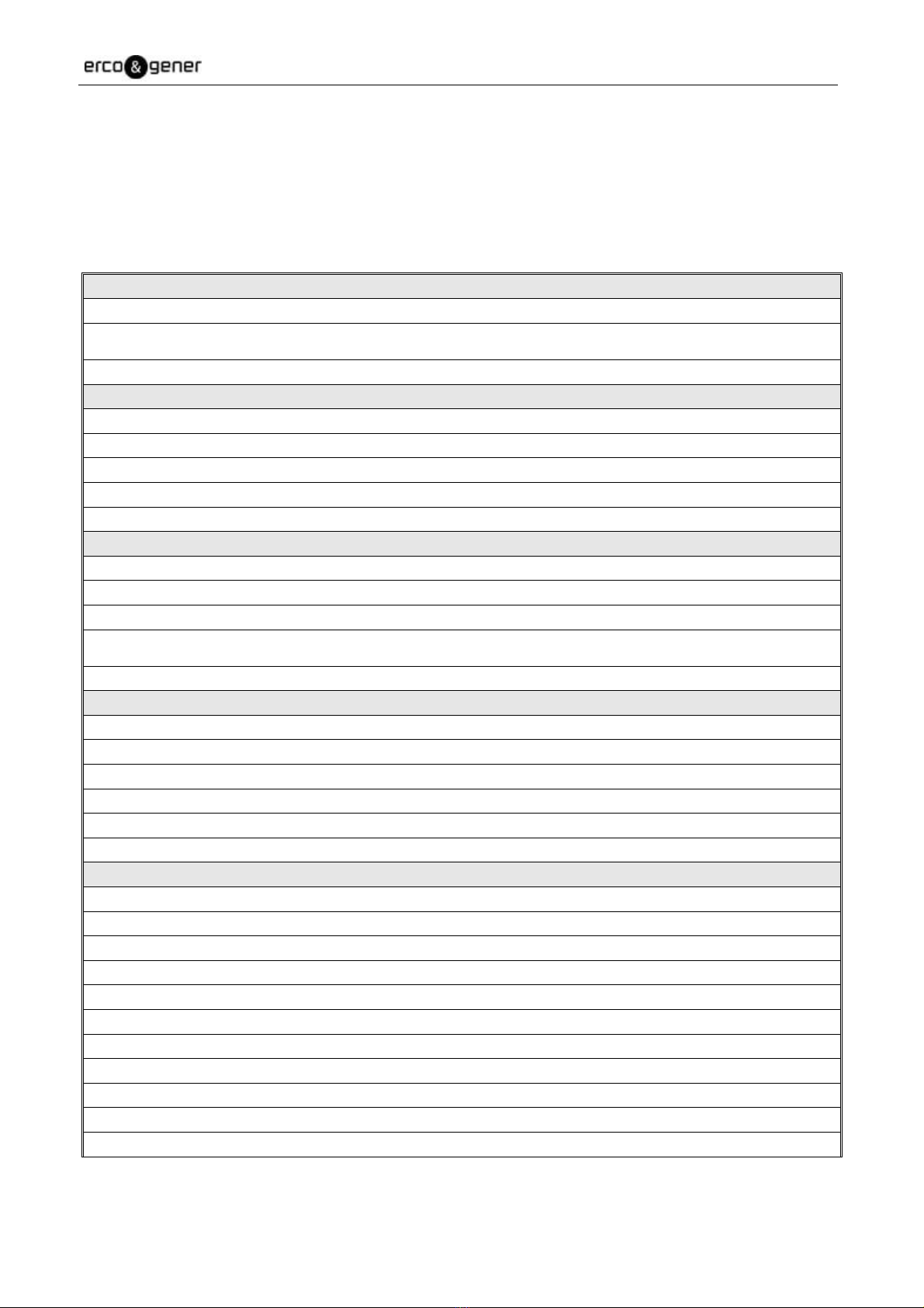
5.1.1 Mounting the modem
To mount the modem on a support, use the fixing brackets as described below.
Fixing brackets
- Must be fixed on a flat surface.
- Max. height of the screw head: 2 mm.
The aluminum casing of the modem is connected to the 0V (GND) of the power supply and to
the 0V of the RS232 serial link. To avoid any risk of conduction of the ground plane to other
equipments,
the modem must be electrically insulated from its mechanical support.
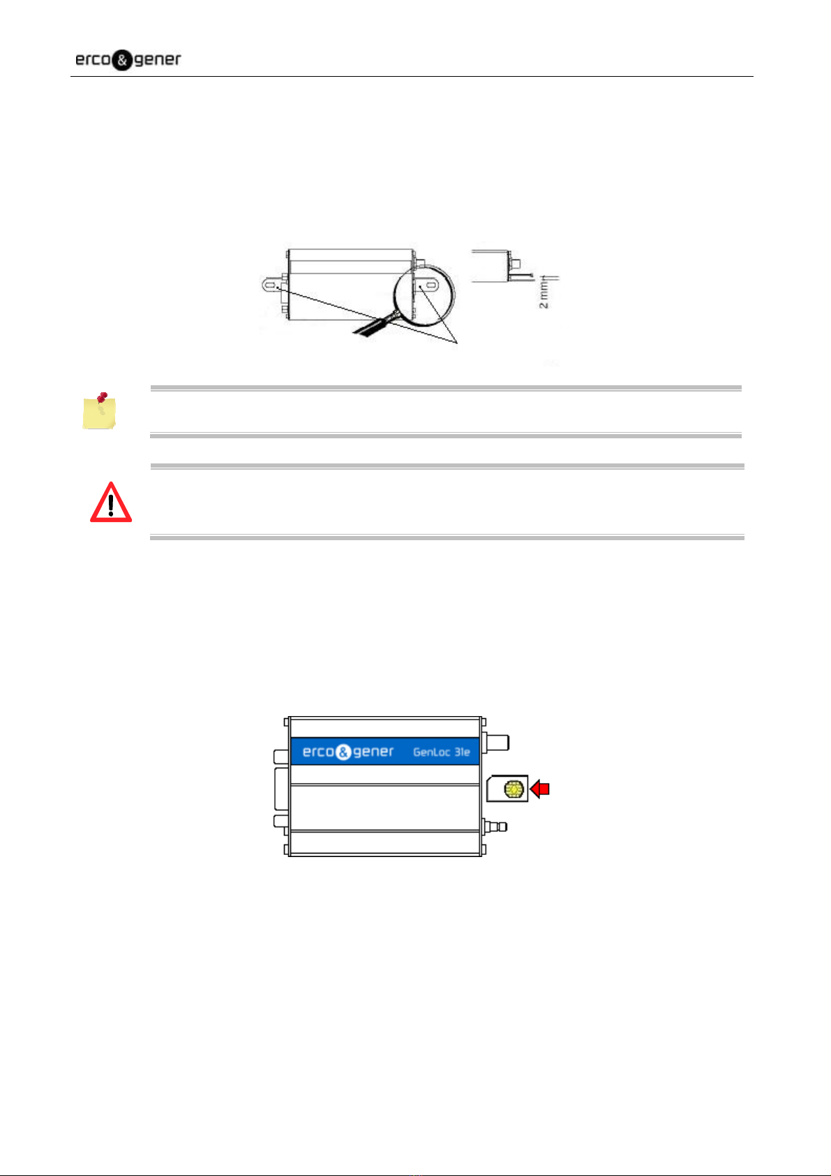
5.1. Installation of the modem
To install the modem, it is recommended to do the following operations with the modem turned off:
- Remove the SIM card cover on the rear side.
- Carefully insert the SIM card into the reader.
Way of insertion
of the SIM card
- Push the SIM card until hearing a "clic" that ensures its correct positioning.
- Put the SIM cover back.
- Connect the GSM antenna to the SMA connector.
- Connect the GPS antenna to the SMB connector.
- For the connection to the DTE, connect the V24 link via the 15-pin Sub HD cable.
- Connect the supply cable to the continuous and regulated power source (for an automobile
application, see the paragraph 5.2).
- Connect the supply cable to the modem and turn on the external power supply.

EG_GenLoc31e_AOB_1003_UG_006_UK Page 20 / 64
Descriptions and non-contractual illustrations in this document are given as an indication only.
ERCO&GENER reserves the right to make any modifications.
The modem is now ready.
There are different cases depending on the application or library installed inside the
equipment:
- Without library: corresponds to the Boot_Loader.
- With EGM standard library.
- The application ERCO & GENER EaseLoc-01.
- The owner application.
5.1.3 Checking the communication with the modem
5.1.3.1 Without Library
The GenLoc 31e AOB does not contain any library, it will return the menu of the Boot-Loader.
Connect the link RS232 between the DTE (the COM port) and the modem (DCE).
Set the RS232 port of the DTE as follows:
Bits per second : 115 200 bps,
Data Bits: 8,
Parity: None,
Stop Bits: 1,
▪Flow control: material.
Use a communication software like HyperTerminal ® of Windows.
Menu by default when there is no library inside the equipment (example of display)
Bootloader V2.27L UE GenLoc 31e AOB (HW0F rev C)
1 - Update application
2 - Erase objects
M - GSM direct access
A - Advanced
E - Exit
With this status, the two leds are off.
In the case where no communication can be established with the modem:
Check the RS232 connection between the DTE and the modem (DCE),
Check the configuration of the COM port of the DTE.
Table of contents
Other Erco&Gener Modem manuals

Erco&Gener
Erco&Gener GENPRO 40E R2 User manual

Erco&Gener
Erco&Gener GenPro 53e User manual

Erco&Gener
Erco&Gener GenPro 20e User manual

Erco&Gener
Erco&Gener GENLoc25 User manual

Erco&Gener
Erco&Gener GenPac 92c User manual

Erco&Gener
Erco&Gener GenPro 325e User manual

Erco&Gener
Erco&Gener GenPro 18e User manual

Erco&Gener
Erco&Gener GenPro 15e User manual

Erco&Gener
Erco&Gener Genloc 31e User manual

Erco&Gener
Erco&Gener Genloc 31e Installation manual


