Erco&Gener GENLoc25 User manual


- 2 -
CONTENTS
I - GENERAL ..............................................................................................................................................................4
II - DESCRIPTION ......................................................................................................................................................4
III - USING THE MODEM ...........................................................................................................................................5
WE RECOMMEND THAT YOU MAKE ALL THE CONNECTIONS WITH THE UNIT UNPOWERED...................................................5
III.1 - INTRODUCTION ................................................................................................................................................5
III.2 - DTE CONNECTION...........................................................................................................................................5
III.3 - CONNECTION TO THE SUPPLY...........................................................................................................................5
III.4 - NETWORK CONNECTION...................................................................................................................................6
III.5 - SWITCHING ON ................................................................................................................................................6
III.6 - SWITCHING OFF THE MODEM ............................................................................................................................6
III.7 - USING THE RESET PIN ...................................................................................................................................7
III.8 - USING THE GPS/DGPS FUNCTION ...................................................................................................................7
IV - HAYES COMMANDS ..........................................................................................................................................8
LINKING THE COMMANDS TOGETHER ............................................................................................................................8
MAIN HAYES COMMANDS...........................................................................................................................................8
V - FUNCTIONING OF THE INPUTS/OUTPUTS ......................................................................................................9
VI - TECHNICAL DATA. ..........................................................................................................................................10
VI.1 - OPERATING CONDITIONS ...............................................................................................................................10
VI.2 - POWER SUPPLY AND CONSUMPTION ..............................................................................................................10
VI.3 - RF PERFORMANCES......................................................................................................................................10
VI.3.1 - GSM ....................................................................................................................................................10
VI.3.2 - GPS .....................................................................................................................................................11
VI.4 - PROTECTION SYSTEMS ..................................................................................................................................11
VII - ADDITIONAL FUNCTIONS..............................................................................................................................11
VII.1 - MODIFICATION OF THE SIGNALS ON V24 ........................................................................................................11
VII.1.1 - GSM_DSR/GPS_RxD2 ......................................................................................................................11
VII.1.2 - GSM_DTR/GPS_TxD2.......................................................................................................................11
VII.2 - MODIFICATION OF THE SUPPLY VOLTAGE FOR THE ACTIVE GPS ANTENNA .......................................................12
VII.3 - SWITCHOVER TO LOW CONSUMPTION FOR THE RS232 (SHUTDOWN) ..............................................................12
APPENDIX I - CONNECTIONS..................................................................................................................................13
SIGNALS FROM THE RS 232 CONNECTOR ..................................................................................................................13
VIEW OF THE FRONT OF THE GEN LOC25 MODEM’S RS232 FEMALE CONNECTOR.........................................................13
SUBD9F-SUBD15M CONNECTION CABLE ................................................................................................................14
POWER SUPPLY CONNECTOR SIGNALS .......................................................................................................................14
VIEW OF THE FRONT OF THE POWER SUPPLY CONNECTOR...........................................................................................14
APPENDIX II - RECOMMENDATIONS .....................................................................................................................15
PROHIBITED CONNECTION DIRECTLY TO A VEHICLE’S BATTERY ....................................................................................15
RECOMMENDED CONNECTION TO A VEHICLE’S BATTERY ..............................................................................................16
CHANGES TO THIS DOCUMENT:
BASIC VERSION MODIFICATIONS ADDED COMPILED BY: DATE
V01 INITIAL CREATION F GOHIER 30/06/04
V02 MECHANICAL DRAWING OF THE CASING P BLANCHARD 21/07/04
V03 I/O MODIFICATION BECAUSE OF CHANGE
TO ED C COPPER VERSION
P BLANCHARD 16/08/04

- 3 -
WARNING
- TO AVOID ANY RISK OF ELECTROCUTION, DO NOT OPEN THE MODEM.
- NO INTERNAL PARTS CAN BE REPAIRED BY THE USER.
- THE MODEM MUST BE RETURNED TO THE FACTORY FOR ANY REPAIRS
- THE MODEM MUST BE SUPPLIED DIRECTLY FROM THE MAINS SUPPLY; A VOLTAGE
ADAPTER MUST BE USED.
With a view to improving their products, GENER reserves the right to modify them at any time,
without notice.

- 4 -
I - GENERAL
The Gen Loc25 is:
- A GSM modem designed to transmit binary data asynchronously, Group 3 fax (Class 2),
SMS and voice.
- AGPS designed for positioning.
II - DESCRIPTION
The Gen Loc25 modem consists of an electronic card placed in an aluminium box of the
following dimensions:
- Length: 73mm (excl. the connectors)
- Width: 54.5mm
- Thickness: 25.5mm
On the front of the casing:
- 4-point Micro-Fit 3.0female connector for the electrical supply and 2 I/Os.
- Sub-D HD 15-point female connector for the V24, telephony and GPS conenctions.
On the rear:
- SMA-F connector for attaching the GSM antenna.
- GSM modem ‘Power ON’ LED.
- SMB-M connector for attaching the GPS antenna.
- ‘GPS positioning active’ LED.
- SIM card holder
Under the casing:
- The CE label and the IMEI number

- 5 -
Block layout:
Micro-Fit 4 pt
SubD-HD 15 pt
Audio
Interface
Interface
RS232 GSM
GPS
DC/DC
PowerSupply
HP
Micro
{
Holder
SIM
Interface
SIM
SMB-M
SMA-F
GSM
GSM
GPS
GPS
{
{
2->1
SWITCH
For details of the signals and connectors used, please refer to Appendix 1.
III - USING THE MODEM
We recommend that you make all the connections with the unit unpowered.
III.1 - Introduction
Before doing anything else, it is prudent to check that the modem is correctly configured and
that all the necessary operating components are present.
The modem is delivered in its own packaging, together with:
- A set of documentation.
- A power cable
- Two fixing bridles
III.2 - DTE connection
A straight 15-point / 9-point cable is used to connect to the DTE via the V24 connection:
Connect the V24 connection to the SUBD15 connector.
The DTE must be configured: 9600 bauds, 8 bits, no parity, 1 stop bit, equipment flow control.
III.3 - Connection to the supply
The GenLoc25 must be connected to a DC supply, controlled by the power cable (please refer
to the power supply ranges in the Electrical Characteristics section).
The modem is protected against excess voltage.
- Internally for surges/transitions >32V DC
- By the 2.5A fuse integrated into the power cable supplied for >32V DC; the modem is
therefore disconnected from the power supply.

- 6 -
III.4 - Network connection
A GSM antenna must be connected to the SMA connector.
A GPS antenna must be connected to the SMB connector.
The GENLoc25 can power an active GPS antenna (see the documentation on “Specific AT
Commands for GPS”).
SIM card: Press the ejector using a pointed object (pencil point) to open the SIM card holder,
insert the SIM card (3V only) in the holder and re-insert the holder.
III.5 - Switching on
Switch the GENLoc25 on.
The GSM LED lights permanently and then flashes once every two seconds.
The GPS LED flashes when it is calculating the position.
If the GSM LED is functioning incorrectly:
- Check that the SIM card or the PIN code are present:
- Send via V24 the command: AT+CPIN?
The modem replies with:
+CPIN: ERROR SIM CARD MISSING
+CPIN: READY PIN code OK
+CPIN: SIM PIN PIN code wrong or not yet entered
+CPIN: SIM PUK PUK code required
-Check the antenna connection.
-Check the reception level:
- Send via V24 the command: AT+CSQ
The modem replies with: +CSQ:<rssi>,<ber>
Rssi: reception level
Ber: reception error code
Rssi must be more than 11; below 15 the signal is perfect.
The modem is now ready to receive incoming calls or to make calls. After an acquisition period
(see the TECHNICAL DATA section, it can also send its position to the DTE.
If the GPS LED is unlit:
- Check the antenna connection.
- Check whether GPS is activated (see the AT command)
- Check the antenna’s position (satellites not in view)
III.6 - Switching off the modem
We would strongly advise against switching off the power to the GENLoc25 during
communication or during dialogue without disconnecting it from the operating network.
In fact, in order to to over-burden the network, you must perform AT+CPOF when switching
the modem off normally.
If AT+CPOF is not done, the modem can remain registered on the network.

- 7 -
In Dialogue mode (excluding communication), before switching off the power, you must send
the following sequence to the modem:
AT+CPOF or AT+CFUN=0 (same function)
The modem replies with OK. The modem is no longer registered on the network and the radio
unit is on standby so the power can now be switched off.
III.7 - Using the RESET PIN
This input enables you to perform a Hardware RESET on the modem.
We would strongly advise against using the RESET function (SUB-D PIN 14) during
communication or during dialogue without disconnecting it from the operating network.
In Dialogue mode (excluding communication), before using the RESET function, you must send
the following sequence to the modem:
AT+CPOF or AT+CFUN=0 (same function)
The modem replies with OK and then the radio unit is put on standby.
RESET is effected by setting SUB-D PIN 14 to 0V (GND).
Warning! There must never be a positive voltage placed on this RESET input (destructive
effect).
III.8 - Using the GPS/DGPS function
The modem has two operating modes:
- GPS with GSM: parameters controlled by AT commands
AT+WGPSPOS which sends the last position data received
AT+WGPSNMEA=1,0,1,2,3,4,5 which, after AT+CFUN=1, sends the NMEA frames
- GSM and GPS separate: parameters controlled by AT commands for the GSM and by UBX
protocol for the GPS units.
For more details on configuring the GENLoc25 modem and its commands specifically for GPS,
please refer to “Specific AT Commands for GPS” for the Q2501 module from WAVECOM,
available on our site www.gener.fr under the heading “Technical Documents”.

- 8 -
IV - HAYES COMMANDS
IMPORTANT:
The AT commands described below are only the main commands in current use. The complete
list of all the Wavecon AT commands and their details are in the compendium of AT commands
available on our site www.gener.fr under the heading “Technical Documents”.
Linking the commands together
The Wavecom modem enables AT commands to be linked together using a semi-colon “;” as
a separator
E.g.: ATE0;+IFC=0,0;&W
Main HAYES commands
ATE ATE1 With echo
ATE0 Without echo
SavingbyAT&W
ATQ ATQ0 With reports (default with AT&F)
ATQ1 Without reports
SavingbyAT&W
ATV ATV0 Messages in code
ATV1 Messages verbal (default with AT&F)
SavingbyAT&W
ATZ Restores the configuration saved in EEPROM.
AT&F Restores and saves the factory configuration.
Warning! Certain commands are not restored;
check the appendix to the list in the compendium of Wavecom
AT commands.
AT&W Saves the current configuration
AT&V Displays the current configuration
AT&D: AT&D0 Forced DTR signal
AT&D1 On a descending foreground, switchover from Transfer to
Dialogue mode. (Default with AT&F)
AT&D2 hang up by DTR: switchover to low status and then high
status. NB: The modem can call or answer without DTR (see
the restrictions on the signals).
AT&S: AT&S0 Forces the DSR signal
AT&S1 The DSR signal follows the communication
AT&C: AT&C0 Forces the DCD signal
AT&C1 The DCD signal follows the communication

- 9 -
V - FUNCTIONING OF THE INPUTS/OUTPUTS
The Gen Loc25 has 2 inputs/outputs (GPIO4 and GPIO1)
Inputs (default):
- Low Level: 0-0.8V DC
- High Level: 2-3V DC
Outputs:
- Low Level: 0-0.1V DC / -2mA
- High Level: 2.7-2.8V DC / 2mA
As an option: configurable as I2C Bus.

- 10 -
VI - TECHNICAL DATA.
VI.1 - Operating conditions
Temperatures
- Operating range: -35°C to + 85°C
- Storage range: - 40°C to + 85°C
Humidity without condensation:
- Operating range: RH < 70% @ +55°C
Atmospheric pressure: normal.
Weight: 95g
VI.2 - Power Supply and consumption
Power Supply
- 5-32V DC GSM / DCS / GPRS Class 2 / GPS
- 5.5-32V DC GPRS Class 10
The modem is protected against excess voltage:
- Internally for surges/transitions >32V DC
- By the 2.5A fuse integrated into the power cable supplied for >32V DC; the modem is
therefore disconnected from the power supply
The GENLoc25 modem’s average consumptions are:
- 8mA at rest @ 12V
- 105mA – @ 12V DC - GSM / GPRS Class 2
- 90mA @ 12V DC - DCS / GPRS Class 2
- 170mA @ 12V DC - GSM / GPRS Class 10
- 125mA @ 12V DC - DCS / GPRS Class 10
- 60mA @ 12V DC - GPS
VI.3 - RF performances
VI.3.1 - GSM
The RF performances comply with the ETSI GSM 05.05 guidelines.
The main reception parameters are:
- For E-GSM900, sensitivity is –104 dBm
- For E-GSM1800, sensitivity is –104 dBm
The main transmission parameters are:
- For E-GSM900, maximum power is 33 dBm at ambient temperature
- For E-GSM1800, maximum power is 30 dBm at ambient temperature

- 11 -
VI.3.2 - GPS
GPS reception sensitivity in normal mode:
- Acquisition mode: -138 dBm
- Moving mode: -146 dBm
GPS Accuracy: 5m (2m with DGPS correction)
Maximum acquisition time upon being switched on: 41 seconds.
Re-acquisition time: <1 second.
16-channel receiver ( f = 1575.42 MHz)
VI.4 - Protection systems
The Gen Loc25 modem is protected:
- By a fuse on the power supply cable: 2.5A 5x20mm
- Against voltages in excess of +32V DC
- Against +V DC polarity inversions
VII - ADDITIONAL FUNCTIONS
The additional functions are selected by inputs/outputs.
VII.1 - Modification of the signals on V24
VII.1.1 - GSM_DSR/GPS_RxD2
The GSM_DSR signal becomes the GPS_RxD2 signal (transmission of the NMEA GPS frames)
Use of input/output GPIO2
AT command:
-AT+WIOW=7,0 (by default, GSM_DSR)
-AT+WIOW=7,1 (GPS_RxD2)
VII.1.2 - GSM_DTR/GPS_TxD2
The GSM_DTR signal becomes the GPS_TxD0 signal (DGPS reception correction)
Use of input/output GPIO3
AT command:
-AT+WIOW=8,0 (by default, GSM_DTR)
-AT+WIOW=8,1 (GPS_TxD0)

- 12 -
VII.2 - Modification of the supply voltage for the active GPS antenna
This provides a choice of 3.3V or 5V.
Use of output GPO1
AT command:
-AT+WIOW=2,0 (by default, GPSVANT = 3.3V)
-AT+WIOW=2,1 (GPSVANT = 5V)
VII.3 - Switchover to low consumption for the RS232 (shutdown)
Use of output GPO0
AT command:
-AT+WIOW=1,0 (by default: RS232 active)
-AT+WIOW=1,1 (RS232 in low consumption, only TxD is active)
- 13 -
APPENDIX I - CONNECTIONS
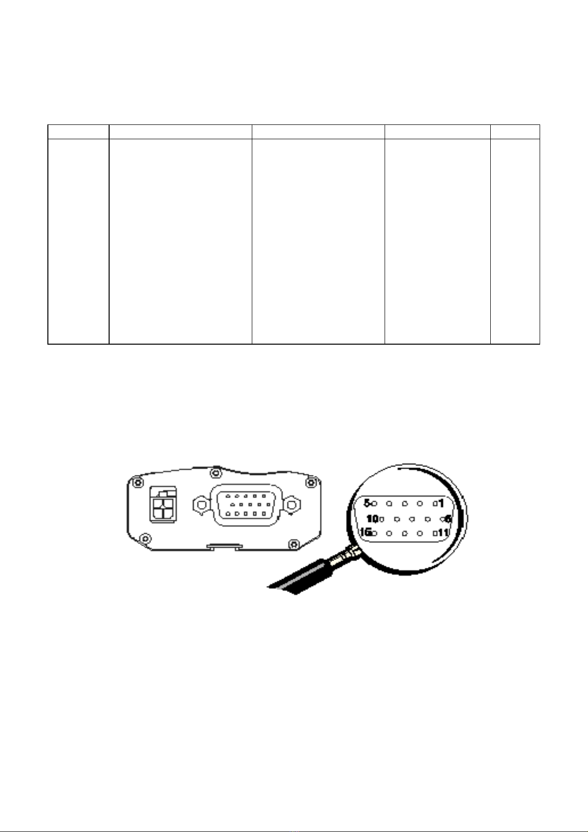
Signals from the RS 232 connector
Pin No. Designation Circuit (V24 – RS232C) GPS multi-plexing I/O
1 Signal detection 109 - DS - DCD OUT
2 Data reception 104 - ED - TxD IN
3 Boot IN
4 Microphone + IN
5 Microphone - IN
6 Data transmission 103 - RD - RxD OUT
7 Data station ready 107 - PDP - DSR NMEA frames OUT
8 Data terminal ready 108/2 - TDP - DTR DGPS correction IN
9 Signal Earth (Ground) 102 - TS - Gnd
10 Loud-speaker + OUT
11 Ready to transmit 106 - PAE - CTS OUT
12 Request to transmit 105 - DPE - RTS IN
13 Call indicator 125 - IA - RI OUT
14 Reset IN
15 Loud-speaker - OUT
View of the front of the Gen Loc25 modem’s RS232 female connector
- 14 -
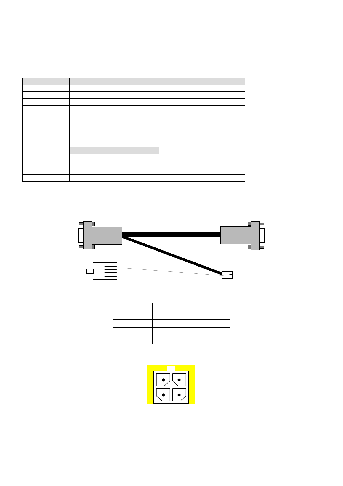
SUBD9F-SUBD15M connection cable
Complete cabling for a GENLoc25 connection to a standard PC serial RS232 port:
Cable with voice option
Designation SUBD 9 F SUBD 15 M-HD
DCD 1 1
RXD 2 6
TXD 3 2
DTR 4 8
GND 5 9
DSR 6 7
RTS 7 12
CTS 8 11
RI 9 13
RJ9
Micro + 1 4
Speaker + 2 10
Speaker - 3 15
Micro - 4 5
Data/audio cable (command code 4404000205)
Sub-D 15 M-HD
Sub-D 9F
RJ9 4P/4C
1
2
3
4
RJ9 (vue côté contacts dorés)
1.8 m
1.8 m
Power supply connector signals
Pin No. Signal
4 +V DC
3 Gnd (Earth)
2 GPIO_4
1 GPIO_1
View of the front of the power supply connector
21
43

- 15 -
APPENDIX II - RECOMMENDATIONS
Prohibited connection directly to a vehicle’s battery
- 16 -
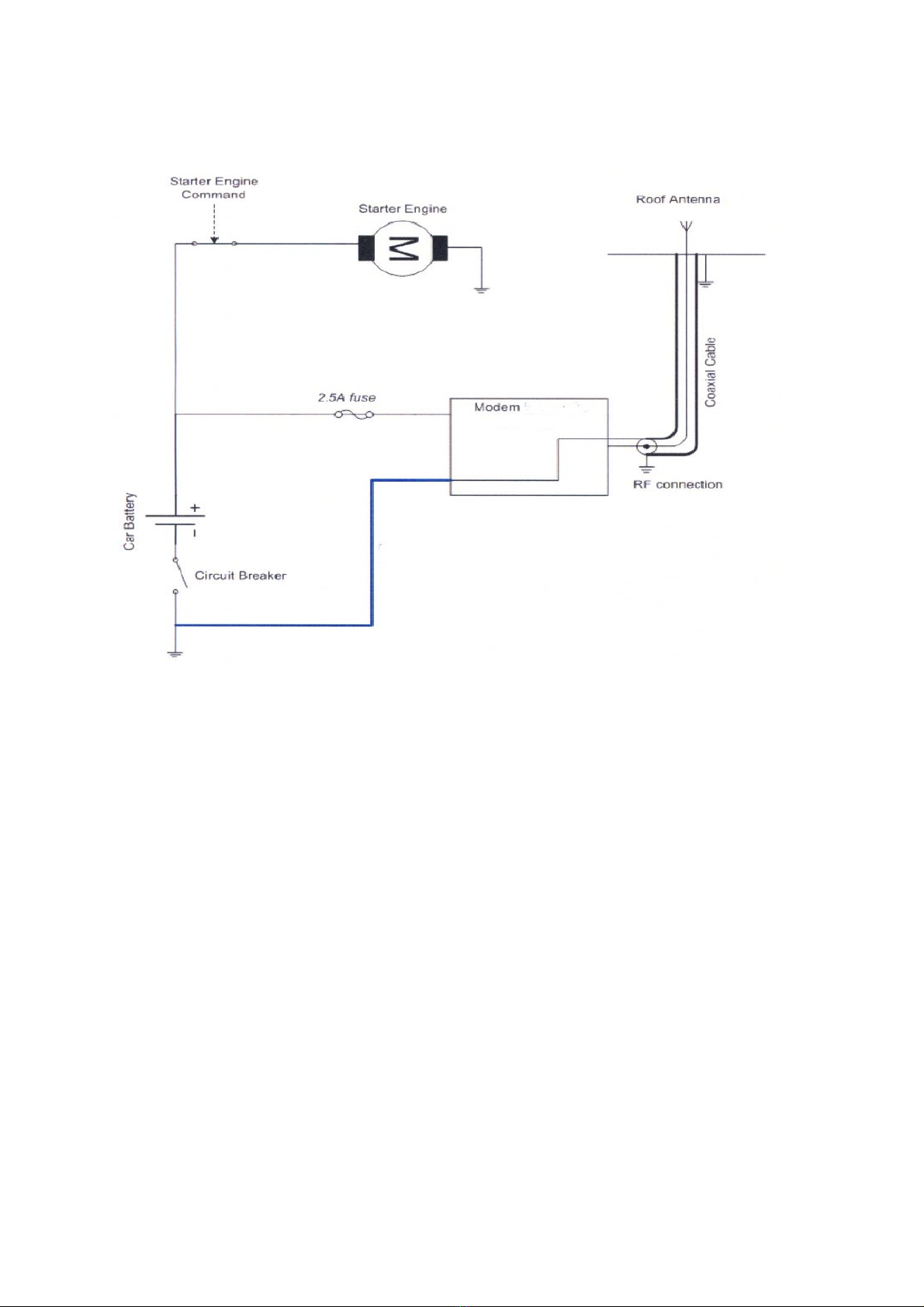
Recommended connection to a vehicle’s battery
Table of contents
Other Erco&Gener Modem manuals

Erco&Gener
Erco&Gener GenPro 325e User manual

Erco&Gener
Erco&Gener GenPro 18e User manual

Erco&Gener
Erco&Gener GenPro 53e User manual

Erco&Gener
Erco&Gener Genloc 31e Installation manual

Erco&Gener
Erco&Gener GenPac 92c User manual

Erco&Gener
Erco&Gener GenLoc 31e AOB User manual

Erco&Gener
Erco&Gener GENPRO 40E R2 User manual

Erco&Gener
Erco&Gener Genloc 31e User manual

Erco&Gener
Erco&Gener GenPro 15e User manual

Erco&Gener
Erco&Gener GenPro 20e User manual


