Ercogener GenLoc 54e User manual

User Guide
GenLoc 54e
Reference : EG_GenLoc54e_1040_UG_002_UK
Revision : 002
Date : 18/04/2018
http://www.ercogener.com Dct_427_02

EG_GenLoc54e_1040_UG_002_UK
Page 2 / 86
Descriptions and non-contractual illustrations in this document are given as an indication only.
ERCOGENER reserves the right to make any modifications. Dct_427_02
Document History
Rev.
Modifications
Author
Date
Validation
Date
000
Creation
YST
04/10/2012
PBR
19/12/2012
001
Add § 5.8 Verification of the modem
registration on the GPRS network
Update § 5.11 Turning OFF the modem
Add § 7.2 Functional optional serial ports
Updating the pin out of the connector μFit 4pts
- Figure 5 : 4-pin Micro-FIT connector
- Table 1 : 4-pin Micro-FIT connector
- Figure 33 : Internal electric scheme of the
inputs
- Figure 35 : Internal electric scheme of the
output
Modification des Consumption
- § 8.2.1 Power supply
- § 8.2.2.1 Motherboard @ 25 °C
Ajout du § 8.2.2.2 Consumption in Low Power
mode @ 25 °C
§ 8.2.9 K-Line compatible input (ISO 91141-2)
- Suppression de la restriction 12 Volts.
- Table 63 : K-Line bus for a Digital
Tachograph
- Figure 41 : Internal electrical scheme of the
K-Line bus for a Digital Tachograph
§ 8.2.14 Power supply output VBAT The
output voltage is 4.8 VDC
§ 8.3 Environmental characteristics update
atmospheric pressure.
Update Dct_427_02
YST
21/05/2015
002
Update battery characteristic
Update the colors of the 14-pins Micro-FIT
cable (Inputs/Outputs).
Update buzzer output current.
Update Warning.
YST
18/04/2018
PBR
21/06/2018
The main modifications of this document compared to the previous version are easily identifiable on the
screen by the blue color of the text.

EG_GenLoc54e_1040_UG_002_UK
Page 3 / 86
Descriptions and non-contractual illustrations in this document are given as an indication only.
ERCOGENER reserves the right to make any modifications. Dct_427_02
TABLE OF CONTENTS
PRESENTATION............................................................................................................................................. 11
WARNING ....................................................................................................................................................... 12
COPYRIGHT ................................................................................................................................................... 13
1REFERENCES........................................................................................................................................ 14
1.1 REFERRED DOCUMENTS.................................................................................................................... 14
1.2 ABBREVIATIONS ............................................................................................................................... 14
1.3 SYMBOLS......................................................................................................................................... 16
2PACKAGING .......................................................................................................................................... 16
2.1 CONTENT......................................................................................................................................... 16
2.2 MODEM PACKAGING ......................................................................................................................... 17
2.3 MODEM LABEL ................................................................................................................................. 17
3GENERAL PRESENTATION ................................................................................................................. 18
3.1 DESCRIPTION ................................................................................................................................... 18
3.1.1 Front side.................................................................................................................................. 18
3.1.2 Back side .................................................................................................................................. 18
3.1.3 Fixing brackets......................................................................................................................... 19
3.2 EXTERNAL CONNECTIONS ................................................................................................................. 20
3.2.1 Connections ............................................................................................................................. 20
3.2.1.1 Antenna connectors........................................................................................................ 20
3.2.1.2 Micro FIT connectors...................................................................................................... 20
3.2.1.3 Audio connector.............................................................................................................. 23
3.2.2 Cables ....................................................................................................................................... 23
3.2.2.1 4-pin Micro-FIT cable ...................................................................................................... 23
3.2.2.2 14-pin Micro-FIT cable (Inputs/Outputs)....................................................................... 25
3.2.2.3 14-wire Micro-FIT cable (Serial links)............................................................................ 26
3.2.2.4 16-pin Micro-FIT cable (Serial links, Boot and Reset) ................................................. 28
4CHARACTERISTICS AND SERVICES.................................................................................................. 29
5USE OF THE MODEM............................................................................................................................ 31
5.1 STARTING WITH THE MODEM.............................................................................................................. 31
5.1.1 Mounting of the modem .......................................................................................................... 31
5.1.2Installation of the modem ....................................................................................................... 31
5.1.3 Checking the communication with the modem .................................................................... 32
5.1.3.1 Without application......................................................................................................... 32
5.1.3.2 Standard library............................................................................................................... 33
5.1.3.3 The application ERCOGENER EaseLoc_Vx ................................................................. 34

EG_GenLoc54e_1040_UG_002_UK
Page 4 / 86
Descriptions and non-contractual illustrations in this document are given as an indication only.
ERCOGENER reserves the right to make any modifications. Dct_427_02
5.1.3.4 The owner application .................................................................................................... 34
5.1.4 SIM card extraction.................................................................................................................. 34
5.1.5 Hardware reset of the modem ................................................................................................ 34
5.2 SPECIFIC RECOMMENDATIONS FOR USE OF THE MODEM IN VEHICLES................................................... 35
5.2.1 Recommended connection on the battery of a truck........................................................... 35
5.2.2 Technical constraints in trucks.............................................................................................. 36
5.3 LEDS OF THE MODEM........................................................................................................................ 37
5.3.1 GSM led of the modem............................................................................................................ 37
5.3.1.1 Without application......................................................................................................... 37
5.3.1.2 With standard library ...................................................................................................... 37
5.3.1.3 The application ERCOGENER EaseLoc_Vx ................................................................. 37
5.3.1.4 Owner application........................................................................................................... 37
5.3.2 GPS led of the modem............................................................................................................. 37
5.3.3 Led 3.......................................................................................................................................... 38
5.3.4 Led 4.......................................................................................................................................... 38
5.3.5 Led 5.......................................................................................................................................... 38
5.3.6 Led 6.......................................................................................................................................... 38
5.4 ECHO FUNCTION OF AT COMMANDS DEACTIVATED............................................................................. 38
5.5 CHECKING THE QUALITY OF THE GSM RECEPTION SIGNAL.................................................................. 39
5.6 VERIFICATION OF THE PIN CODE ....................................................................................................... 40
5.7 VERIFICATION OF THE MODEM REGISTRATION ON THE GSM NETWORK................................................ 40
5.8 VERIFICATION OF THE MODEM REGISTRATION ON THE GPRS NETWORK.............................................. 41
5.9 READING A CURRENT POSITION GIVEN BY THE GPS ........................................................................... 41
5.10 MAIN AT COMMANDS (HAYES)........................................................................................................ 43
5.11 TURNING OFF THE MODEM ............................................................................................................... 44
5.1 MODEM UPDATING PROCEDURE......................................................................................................... 45
6TROUBLE SHOOTING .......................................................................................................................... 45
6.1 PROBLEM OF COMMUNICATION BETWEEN THE MODEM AND THE RS232 LINK (V24)............................. 45
6.2 "ERROR" MESSAGE........................................................................................................................ 46
6.3 "NO CARRIER" MESSAGE .............................................................................................................. 46
7FUNCTIONAL DESCRIPTION............................................................................................................... 48
7.1 FUNCTIONAL ARCHITECTURE............................................................................................................. 48
7.2 FUNCTIONAL OPTIONAL SERIAL PORTS .............................................................................................. 48
7.3 POWER SUPPLY................................................................................................................................ 49
7.3.1 General presentation............................................................................................................... 49
7.3.2 Internal battery......................................................................................................................... 49
7.3.2.1 Presentation of the internal battery............................................................................... 49
7.3.2.2 Specifications of internal battery .................................................................................. 50
7.3.2.3 Charge and power supply voltage................................................................................. 50
7.3.2.4 Indication of presence/absence of external power supply......................................... 50
7.3.2.5 Instructions and restrictions of use.............................................................................. 51

EG_GenLoc54e_1040_UG_002_UK
Page 5 / 86
Descriptions and non-contractual illustrations in this document are given as an indication only.
ERCOGENER reserves the right to make any modifications. Dct_427_02
7.3.3 Protections of the power supply............................................................................................ 51
7.4 RS232 SERIAL LINK.......................................................................................................................... 51
7.4.1 Serial link RS232_0.................................................................................................................. 52
7.4.2 Serial link RS232_1.................................................................................................................. 52
7.4.3 Serial link K-Line (ISO 91141-2).............................................................................................. 53
7.4.4 Serial link RS232_2 / CAN Bus ............................................................................................... 54
7.4.4.1 RS232_2 ........................................................................................................................... 54
7.4.4.2 CAN Bus........................................................................................................................... 54
7.5 INPUTS/OUTPUTS FUNCTIONING ........................................................................................................ 56
7.5.1 Management of logical outputs.............................................................................................. 56
7.5.2 Management of logical Inputs ................................................................................................ 57
7.5.3 Management of analog Inputs................................................................................................ 57
7.6 OPTION 2ND SIM CARD READER......................................................................................................... 58
7.7 BOOT............................................................................................................................................. 58
7.8 RESET............................................................................................................................................ 58
7.8.1 General presentation............................................................................................................... 58
7.8.2 RESET sequence ..................................................................................................................... 59
7.9 WATCHDOG..................................................................................................................................... 59
7.10 AUDIO.............................................................................................................................................. 60
7.10.1 Microphone inputs............................................................................................................... 60
7.10.2 Loudspeaker outputs (Speaker)......................................................................................... 60
7.10.3 Buzzer outputs..................................................................................................................... 61
7.11 GPS MODULE................................................................................................................................... 61
7.12 ACCELEROMETER............................................................................................................................. 61
7.13 INTERNAL PROCESSOR ..................................................................................................................... 62
7.13.1 EGM presentation................................................................................................................ 62
7.13.2 EGM architecture................................................................................................................. 62
8TECHNICAL CHARACTERISTICS........................................................................................................ 63
8.1 MECHANICAL CHARACTERISTICS....................................................................................................... 63
8.2 ELECTRICAL CHARACTERISTICS ........................................................................................................ 64
8.2.1 Power supply............................................................................................................................ 64
8.2.2 Consumption............................................................................................................................ 65
8.2.2.1 Motherboard @ 25 °C...................................................................................................... 65
8.2.2.2 Consumption in Low Power mode @ 25 °C.................................................................. 65
8.2.2.3 Consumption of battery charge @ 25 °C ...................................................................... 65
8.2.2.4 Consumption of GSM module @ 25 °C......................................................................... 65
8.2.2.5 Consumption of GPS module @ 25 °C.......................................................................... 66
8.2.2.6 Consumption of a GPS active antenna @ 25 °C .......................................................... 66
8.2.2.7 Consumption of motherboard on battery @ 25 °C ...................................................... 66
8.2.2.8 Consumption of GSM module on battery @ 25 °C ...................................................... 66
8.2.2.9 Consumption of GPS module on battery @ 25 °C....................................................... 67

EG_GenLoc54e_1040_UG_002_UK
Page 6 / 86
Descriptions and non-contractual illustrations in this document are given as an indication only.
ERCOGENER reserves the right to make any modifications. Dct_427_02
8.2.2.10 Consumption of a GPS active antenna on battery @ 25 °C........................................ 67
8.2.2.11 Max consumption............................................................................................................ 67
8.2.3 Audio interface......................................................................................................................... 68
8.2.3.1 Microphone...................................................................................................................... 68
8.2.3.2 Loudspeaker.................................................................................................................... 69
8.2.3.3 Buzzer............................................................................................................................... 70
8.2.4 Inputs/Output............................................................................................................................ 71
8.2.4.1 Opto-coupled inputs....................................................................................................... 71
8.2.4.2 Opto-coupled inputs insulated ...................................................................................... 72
8.2.4.3 Outputs............................................................................................................................. 73
8.2.4.4 Analog inputs .................................................................................................................. 74
8.2.5 SIM interface............................................................................................................................. 74
8.2.6 Option 2nd SIM interface.......................................................................................................... 74
8.2.7 RESET signal............................................................................................................................ 75
8.2.8 One Wire Bus............................................................................................................................ 76
8.2.9 K-Line compatible input (ISO 91141-2).................................................................................. 77
8.2.10 Characteristics of the RS232 serial links.......................................................................... 78
8.2.11 RF GSM/DCS characteristics.............................................................................................. 78
8.2.11.1 GSM external antenna..................................................................................................... 79
8.2.12 GPS characteristics............................................................................................................. 79
8.2.12.1 GPS functioning .............................................................................................................. 79
8.2.12.2 GPS external antenna..................................................................................................... 80
8.2.12.3 Installation of the GPS external antenna...................................................................... 80
8.2.13 Characteristics of the accelerometer ................................................................................ 81
8.2.14 Power supply output VBAT ................................................................................................ 81
8.2.15 Power supply Power_Out ................................................................................................... 81
8.2.16 Option power supply 100V ................................................................................................. 83
8.3 ENVIRONMENTAL CHARACTERISTICS ................................................................................................. 83
9SECURITY RECOMMENDATIONS ....................................................................................................... 84
9.1 GENERAL SECURITY ......................................................................................................................... 84
9.2 SECURITY IN A VEHICLE .................................................................................................................... 85
9.3 CARE AND MAINTENANCE.................................................................................................................. 85
9.4 YOUR RESPONSIBILITY...................................................................................................................... 85
10 RECOMMENDED ACCESSORIES........................................................................................................ 86
11 CUSTOMER SUPPORT......................................................................................................................... 86

EG_GenLoc54e_1040_UG_002_UK
Page 7 / 86
Descriptions and non-contractual illustrations in this document are given as an indication only.
ERCOGENER reserves the right to make any modifications. Dct_427_02
Index of Tables
Table 1 : 4-pin Micro-FIT connector ................................................................................................................ 20
Table 2 : 14-pin µFit connector........................................................................................................................ 21
Table 3 : 16-pin Micro-FIT connector .............................................................................................................. 22
Table 4 : Connector RJ9 audio........................................................................................................................ 23
Table 5 : Characteristics of power supply cable.............................................................................................. 24
Table 6 : Characteristics of 14-wire Inputs/Outputs cable............................................................................... 25
Table 7 : 14-wire Inputs/Outputs cable............................................................................................................ 25
Table 8 : Characteristic 14-wire serial link cable............................................................................................. 26
Table 9 : Wiring of 14-wire serial links cable................................................................................................... 27
Table 10 : Characteristic 16-wire serial link cable (Boot + Reset)................................................................... 28
Table 11 : Wiring of 16-wire serial link cable (Boot + Reset) .......................................................................... 28
Table 12 : Characteristics and services........................................................................................................... 29
Table 13 : Status of GSM LED ........................................................................................................................ 37
Table 14 : Status of GPS LED......................................................................................................................... 37
Table 15 : Value RSSI..................................................................................................................................... 39
Table 16 : Verification of the PIN code............................................................................................................ 40
Table 17 : Verification of modem registration on GSM network...................................................................... 40
Table 18 : Verification of modem registration on GPRS network.................................................................... 41
Table 19 : Reading a current position given by the GPS ................................................................................ 43
Table 20 : Main AT commands used with the modem .................................................................................... 43
Table 21 : Solutions when there is no dialogue between the modem and the RS232 link ............................. 45
Table 22 : Solutions when a message "NO CARRIER" is returned ................................................................ 47
Table 23 : Characteristics of the polymer lithium battery ................................................................................ 50
Table 24 : Examples of responses with the internal battery option cabled ..................................................... 50
Table 25 : Description of pins of serial link RS232_0...................................................................................... 52
Table 26 : Description of pins of serial link RS232_1...................................................................................... 53
Table 27 : Description of pin K-Line ................................................................................................................ 53
Table 28 : Description of pins of serial link RS232_2...................................................................................... 54
Table 29 : Description of pins of serial link CAN ............................................................................................. 55
Table 30 : Example of management of logical Outputs................................................................................... 56
Table 31 : Example of management of logical Inputs ..................................................................................... 57
Table 32 : Example of management of analog Inputs..................................................................................... 57
Table 33 : Description of the RESET signal pin .............................................................................................. 58
Table 34 : Description of connector RJ9 ......................................................................................................... 60
Table 35 : Description of micro Input of RJ9 connector .................................................................................. 60
Table 36 : Description of loudspeaker output of RJ9 connector...................................................................... 60
Table 37 : Description of buzzer Output.......................................................................................................... 61
Table 38 : Mechanical characteristics ............................................................................................................. 63
Table 39 : Electrical characteristics................................................................................................................. 64

EG_GenLoc54e_1040_UG_002_UK
Page 8 / 86
Descriptions and non-contractual illustrations in this document are given as an indication only.
ERCOGENER reserves the right to make any modifications. Dct_427_02
Table 40 : Effects of power supply defect........................................................................................................ 64
Table 41 : Motherboard consumption @ 25 °C............................................................................................... 65
Tableau 42 : Consumption in Low Power mode @ 25 °C.............................................................................. 65
Table 43 : Consumption of battery charge @ 25 °C........................................................................................ 65
Table 44 : Consumption of GSM module @ 25 °C.......................................................................................... 65
Table 45 : Consumption of GPS module @ 25 °C .......................................................................................... 66
Table 46 : Consumption of a GPS active antenna GPS @ 25 °C................................................................... 66
Table 47 : Consumption of motherboard on battery @ 25 °C......................................................................... 66
Table 48 : Consumption of GSM module on battery @ 25 °C ........................................................................ 66
Table 49 : Consumption of GPS module on battery @ 25 °C......................................................................... 67
Table 50 : Consumption of a GPS active antenna on battery @ 25 °C .......................................................... 67
Table 51 : Polarization characteristics for a dynamic microphone.................................................................. 68
Table 52 : Characteristics recommended for the dynamic microphone.......................................................... 68
Table 53 : Characteristics of Output for loudspeaker...................................................................................... 69
Table 54 : Characteristics of buzzer output..................................................................................................... 70
Table 55 : Example of transducer tested with the GenLoc 54e....................................................................... 70
Table 56 : Characteristics of opto-coupled inputs ........................................................................................... 71
Table 57 : Pin out of insulated inputs .............................................................................................................. 72
Table 58 : Characteristics of open-collector output......................................................................................... 73
Table 59 : Characteristics of analog inputs ..................................................................................................... 74
Table 60 : Characteristics of SIM card supply voltage .................................................................................... 74
Table 61 : Conditions of use of RESET signal ................................................................................................ 75
Table 62 : One Wire Bus –Electrical characteristics of the ARM ................................................................... 76
Table 63 : K-Line bus for a Digital Tachograph............................................................................................... 77
Table 64 : Characteristics of the UART........................................................................................................... 78
Table 65 : Parameters of the RF receiver and transmitter.............................................................................. 78
Table 66 : Characteristics of the GSM external antenna................................................................................. 79
Table 67 : GPS parameters............................................................................................................................. 79
Table 68 : Characteristics of the GPS external antenna ................................................................................. 80
Table 69 : Characteristics of the accelerometer.............................................................................................. 81
Table 70 : Description of the power supply VBAT ............................................................................................. 81
Table 71 : Conditions of use of the power supply output VBAT ........................................................................ 81
Table 72 : Environmental characteristics......................................................................................................... 83

EG_GenLoc54e_1040_UG_002_UK
Page 9 / 86
Descriptions and non-contractual illustrations in this document are given as an indication only.
ERCOGENER reserves the right to make any modifications. Dct_427_02
Index of Figures
Figure 1 : Content............................................................................................................................................ 16
Figure 2 : Front side......................................................................................................................................... 18
Figure 3 : Back side......................................................................................................................................... 18
Figure 4 : Back side......................................................................................................................................... 19
Figure 5 : 4-pin Micro-FIT connector............................................................................................................... 20
Figure 6 : 14-pin Micro-FIT connector............................................................................................................. 21
Figure 7 : 16-pin Micro-FIT connector............................................................................................................. 22
Figure 8 : Connector RJ9 audio....................................................................................................................... 23
Figure 9 : 4-pin power supply cable................................................................................................................. 23
Figure 10 : Fuse Mini Blade............................................................................................................................. 24
Figure 11 : 14-wire Inputs/Outputs cable......................................................................................................... 25
Figure 12 : 14-wire serial link cable................................................................................................................. 26
Figure 13 : 16-wire serial link (Boot + Reset) .................................................................................................. 28
Figure 14 : Mounting of the modem................................................................................................................. 31
Figure 15 : Installation of the modem .............................................................................................................. 31
Figure 16 : Recommended connection on the battery of a truck..................................................................... 35
Figure 17 : Forbidden electrical connection (risk of damage on the modem) ................................................. 36
Figure 18 : Functional architecture.................................................................................................................. 48
Figure 19 : Functional optional serial ports...................................................................................................... 48
Figure 20 : Normalized signals of the serial link RS232_0.............................................................................. 52
Figure 21 : Normalized signals of serial link RS232_1.................................................................................... 53
Figure 22 : K-Line signal.................................................................................................................................. 53
Figure 23 : Normalized signals of serial link RS232_2.................................................................................... 54
Figure 24 : Normalized signals of serial link CAN ........................................................................................... 55
Figure 25 : Chronogram of RESET signal....................................................................................................... 59
Figure 26 : positioning of the accelerometer axis............................................................................................ 61
Figure 27 : Software architecture .................................................................................................................... 62
Figure 28 : Dimensions.................................................................................................................................... 63
Figure 29 : Max consumption .......................................................................................................................... 67
Figure 30 : Micro interface............................................................................................................................... 69
Figure 31 : Loudspeaker interface................................................................................................................... 69
Figure 32 : Example of transducer tested with the GenLoc 54e ..................................................................... 70
Figure 33 : Internal electric scheme of the inputs............................................................................................ 71
Figure 34 : Internal electrical scheme of insulated inputs ............................................................................... 72
Figure 35 : Internal electric scheme of the output ........................................................................................... 73
Figure 36 : Example of relay control................................................................................................................ 73
Figure 37 : Internal electrical scheme of analog input..................................................................................... 74
Figure 38 : Wiring scheme of RESET signal................................................................................................... 75
Figure 39 : Internal electrical scheme of the One Wire bus ............................................................................ 76

EG_GenLoc54e_1040_UG_002_UK
Page 10 / 86
Descriptions and non-contractual illustrations in this document are given as an indication only.
ERCOGENER reserves the right to make any modifications. Dct_427_02
Figure 40 : Scheme of connection of the K-Line input on a Digital Tachograph............................................. 77
Figure 41 : Internal electrical scheme of the K-Line bus for a Digital Tachograph.......................................... 77
Figure 42 : Level of K-Line bus for a Digital Tachograph................................................................................ 77
Figure 43 : Recommended installation of GPS antenna ................................................................................. 80
Figure 44 : Installation of GPS antenna not recommended ............................................................................ 80
Figure 45 : Internal electrical scheme of the Power_Out ................................................................................ 82
Figure 46 : Drop of voltage.............................................................................................................................. 82

EG_GenLoc54e_1040_UG_002_UK
Page 11 / 86
Descriptions and non-contractual illustrations in this document are given as an indication only.
ERCOGENER reserves the right to make any modifications. Dct_427_02
Presentation
Entirely dedicated to geo-localization and embedded data services, the modem GenLoc 54e combines the
GSM / GPRS and GPS functions in the same robust casing.
The GPS data can be transmitted by SMS or data GSM/GPRS communication.
This product includes the GPS function 50 channels. The GPS high sensitivity solution ensures the data
collection in difficult environments.
The modem is Quad-Bands (850/900/1800/1900 MHz) GSM/GPRS Class 10.
The GenLoc 54e provides 3 operating modes:
▪External mode (standard): The control is done by an external application. The modem is used with
the AT command set (see Commands List EG_EGM_CL_xxx_yy of ERCOGENER).
▪Autonomous mode (optional): Once configured, the modem is autonomous, it cyclically registers the
positions and tranmits them automatically to the client’s application via different services: SMS, GSM
Data, TCP socket GPRS (see EG_EaseLoc_Vx_CL_yyy_UK of ERCOGENER).
▪Specific development mode: the EGM development tool allows a development of additional and
customized applications. For more information about the tools and the training, please contact our
sales department.
Its protocols of IP connectivity integrated in the embedded application EaseLoc_Vx, are also available under
EGM libraries for a specific development, allowing a quick installation of embedded telematics solutions with
high added-value.
This document describes the modem and provides the following information:
- General presentation,
- Functional description,
- Available basic services,
- Installation and use of the modem (first level),
- Trouble shooting,
- Recommended accessories for the use of the modem.
For more information about this document, ERCOGENER puts at your disposal the following elements:
- Commands List
External Mode EG_EGM_CL_xxx_yy
Autonomous Mode EG_EaseLoc_Vx_CL_yyy_UK
- Application Note EG_GenLoc54e_1040_AN_xxx_yy
- Release Note EG_GenLoc54e_1040_RL_xxx_yy
- Certificate of Origine, Conformity …
- Client support (Hot-Line)
These different documents are available on our website www.ercogener.com in the download
area of the product concerned..

EG_GenLoc54e_1040_UG_002_UK
Page 12 / 86
Descriptions and non-contractual illustrations in this document are given as an indication only.
ERCOGENER reserves the right to make any modifications. Dct_427_02
Warning
The GenLoc 54e is dedicated to 'Machine To Machine' (M2M) applications only.
ERCOGENER recommends the use of SIM card subscriptions type 'Machine To Machine'
(M2M).
Video, VoIP (Voice over IP) transfer requires the payment of additional royalties.
ERCOGENER advises to read carefully all documents linked to the product GenLoc 54e (User Guide,
Application Notes, Command List).
ERCOGENER cannot be held responsible for:
- The problems due to an inappropriate use of the GenLoc 54e.
- The problems due to a wrong configuration
- The problems due to a wrong use of an embedded software application developed or supplied by a
third party.
- The dysfunctions due to the absence, a bad coverage or termination of the GSM, GPRS and GNSS
networks services.
- The dysfunctions if the product is used for the watching of physical persons where human life is
engaged.
ERCOGENER reserves the right to modify the functions of its products "GenLoc 54e" and "EaseLoc"
without previous notice.
- To avoid any risk of electrocution, do not open the casing.
- For any functioning, the casing must be closed.
- No internal part can be repaired by the user. The GenLoc 54e must be returned to the factory for any repair
preceded by RMA request (Return Material Authorization).
- The GenLoc 54e must be placed in a normally ventilated area, out of sources of heat.
- In order to guarantee the electromagnetic compatibility, the length of the serial cable, the power supply
cable and the inputs/outputs cable must not exceed 3 meters.
- The GenLoc 54e must not be connected directly to the mains supply (230 VAC); a voltage adapter must be
used.
This marking on the product, accessories, packaging or literature indicates that the product
and its electronic accessories (e.g. cable etc.) should not be disposed of with other household
waste.

EG_GenLoc54e_1040_UG_002_UK
Page 13 / 86
Descriptions and non-contractual illustrations in this document are given as an indication only.
ERCOGENER reserves the right to make any modifications. Dct_427_02
Copyright
The reproduction, transfer, distribution or storage of part or the totality of the contents of this document, in
any form, without the prior written authorization of ERCOGENER is strictly prohibited.
GenLoc 54e is a trademark of ERCOGENER.
Hayes is a registered trademark of Hayes Microcomputer Product Inc. The names of products and
companies mentioned in this document may be names or trademarks of their respective holders.
The use of some products or services described in this document may require a paying subscription. The
availability of some products or services described in this document may change, depending on the
configurations and the materials.
In some countries, restrictions of use of the devices may be applied. For more information, thank you to
contact your nearest legally qualified local government representative.
ERCOGENER follows a method of continuous development. Consequently, ERCOGENER reserves the right
to change and improve any of its products described in this document, without notice.
The contents of this document are provided “as it is”. Except for the applicable obligatory laws, no guarantee
in any form, explicit or implicit, including but without being limited to it the implicit guarantees of aptitude to
marketing and of appropriateness to a particular use, is granted concerning the precision, the liability or the
contents of this document. ERCOGENER reserves the right to revise or withdraw this document at any time
and without notice.
ERCOGENER cannot be held responsible for any loss of data or income, as well as particular
damage, incidental, consecutive or indirect.

EG_GenLoc54e_1040_UG_002_UK
Page 14 / 86
Descriptions and non-contractual illustrations in this document are given as an indication only.
ERCOGENER reserves the right to make any modifications. Dct_427_02
1 References
1.1 Referred documents
Commands List of
Standard library of ERCOGENER ..................................... : EG_EGM_CL_xxx_yy
Embedded application EaseLoc of ERCOGENER............ : EG_EaseLoc_Vx_CL_yyy_UK
Application Notes GenLoc 54e of ERCOGENER.............. : EG_GenLoc54e_1040_AN_xxx_yy
GSM reference documents:
● GSM 07.05.
●GSM 07.07.
1.2 Abbreviations
Abbreviations definition
AC
Alternative Current
ACM
Accumulated Call Meter
AMR
Adaptive Multi-Rate
AT
Attention (prefix for modem commands)
BTS
Base Transceiver Station
CLK
ClocK
CMOS
Complementary Metal Oxide Semiconductor
CS
Coding Scheme
CTS
Clear To Send
dB
Decibel
dBc
Decibel relative to the Carrier power
dBi
Decibel relative to an Isotropic radiator
dBm
Decibel relative to one milliwatt
DC
Direct Current
DCD
Data Carrier Detect
DCE
Data Communication Equipment
DCS
Digital Cellular System
DSR
Data Set Ready
DTE
Data Terminal Equipment
DTMF
Dual Tone Multi-Frequency
DTR
Data Terminal Ready
EEPROM
Electrically Erasable Programmable Read-Only Memory
EFR
Enhanced Full Rate
EGM
Erco Gener Middleware
E-GSM
Extended GSM
EMC
ElectroMagnetic Compatibility
EMI
ElectroMagnetic Interference
ESD
ElectroStatic Discharges
ETSI
European Telecommunications Standards Institute
FIT
Series of connectors (micro-FIT)
FR
Full Rate
FTA
Full Type Approval
FTP
File Transfert Protocol
GCF
Global Certification Forum
GND
GrouND
GPIO
General Purpose Input Output
GPRS
General Packet Radio Service
GPS
Global Positioning System

EG_GenLoc54e_1040_UG_002_UK
Page 15 / 86
Descriptions and non-contractual illustrations in this document are given as an indication only.
ERCOGENER reserves the right to make any modifications. Dct_427_02
GSM
Global System for Mobile communications
HR
Half Rate
I
Input
IEC
International Electrotechnical Commission
IMEI
International Mobile Equipment Identification
I/O
Input / Output
LED
Light Emitting Diode
LLC
Low Level Command
MAX
MAXimum
ME
Mobile Equipment
MIC
MICrophone
Micro FIT
Family of connectors from Molex
MIN
MINimum
MNP
Microcom Networking Protocol
MO
Mobile Originated
MS
Mobile Station
MT
Mobile Terminated
NOM
NOMinal
O
Output
Pa
Pascal (for speaker sound pressure measurements)
PBCCH
Packet Broadcast Control Channel
PC
Personal Computer
PCL
Power Control Level
PDP
Packet Data Protocol
PIN
Personal Identity Number
PLMN
Public Land Mobile Network
PUK
Personal Unblocking Key
RF
Radio Frequency
RFI
Radio Frequency Interference
RI
Ring Indicator
RMS
Root Mean Square
RTS
Request To Send
RX
Receive
SIM
Subscriber Identification Module
SMA
SubMiniature version A RF connector
SMB
SubMiniature version B RF connector
SMS
Short Message Service
SNR
Signal-to-Noise Ratio
SNTP
Simple Network Time Protocol
SPI
Serial Peripheral Interface
SPL
Sound Pressure Level
SPK
SpeaKer
SRAM
Static RAM
TCP/IP
Transmission Control Protocol / Internet Protocol
TDMA
Time Division Multiple Access
TU
Typical Urban fading profile
TUHigh
Typical Urban, High speed fading profile
TX
Transmit
TYP
TYPical
UTC
Universal Time Clock
VSWR
Voltage Stationary Wave Ratio

EG_GenLoc54e_1040_UG_002_UK
Page 16 / 86
Descriptions and non-contractual illustrations in this document are given as an indication only.
ERCOGENER reserves the right to make any modifications. Dct_427_02
1.3 Symbols
The following symbols are used to highlight the important information of this userguide.
A symbol for the essential information linked to the module integration and performance.
A warning symbol indicates the actions that could harm or damage the module
2 Packaging
2.1 Content
The GenLoc 54e is supplied with:
- a GenLoc 54e cardboard packaging,
- a modem GenLoc 54e,
- 2 fixing brackets,
- a 4-wire power supply cable, input/output (Red/Black/Yellow/Brown) stripped with fuse.
- a 14-wire stripped cable equipped with a 14-pin connector, Inputs/Outputs.
- a 14-wire cable equipped with a 16-pin connector, with a Sub- D 9 pins and stripped wires.
- a technical sheet (Instructions Sheet).
Figure 1 : Content

EG_GenLoc54e_1040_UG_002_UK
Page 17 / 86
Descriptions and non-contractual illustrations in this document are given as an indication only.
ERCOGENER reserves the right to make any modifications. Dct_427_02
2.2 Modem packaging
The external dimensions of the modem packaging are:
- Width : 160 mm,
- Height : 280 mm,
- Length : 64 mm.
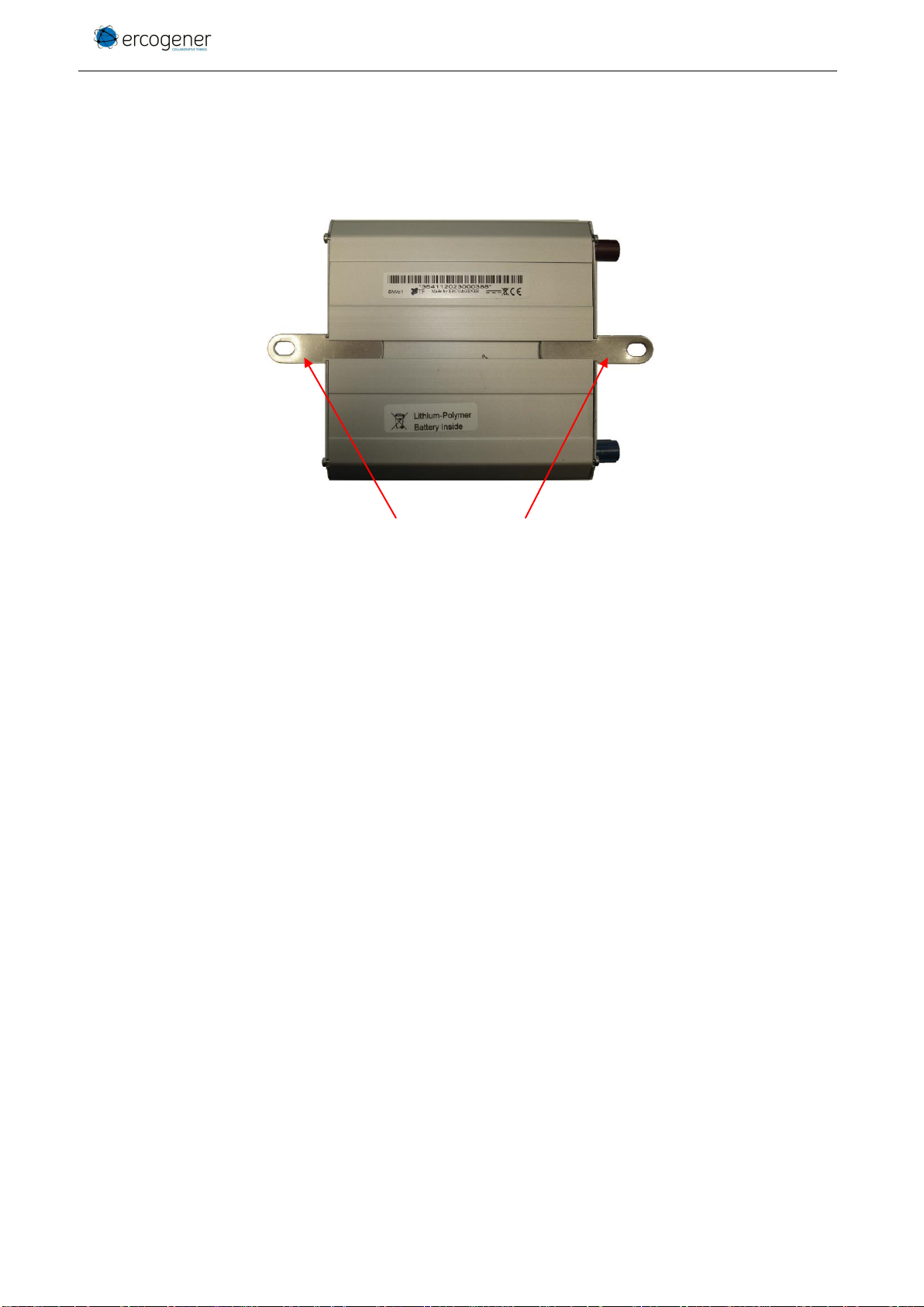
2.3 Modem label
On the standard casing, there are 2 labels placed on the back side of the modem:
▪A production label indicating the following information: (see picture of paragraph Fixing brackets )
- The CE mark,
- The crossed wheelie-bin mark (DEEE standards),
- The direct current mark (VDC),
- The IMEI bar code with 15 digits.
If the internal battery option has been mounted during production, the modem has the
following label: Lithium-Polymer Battery Inside.
EG_GenLoc54e_1040_UG_002_UK
Page 18 / 86
Descriptions and non-contractual illustrations in this document are given as an indication only.
ERCOGENER reserves the right to make any modifications. Dct_427_02
3 General presentation
3.1 Description
Description of the modem GenLoc 54e:
3.1.1 Front side
Figure 2 : Front side
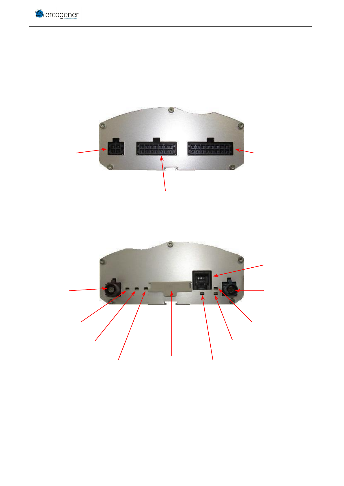
3.1.2 Back side
Figure 3 : Back side
Micro-FIT
connector 4pin/M
Micro-FIT
connector 14pin/M
Micro-FIT
connector 16pin/M
FAKRA-C
connector
GPS antenna
FAKRA-D
connector
GSM antenna
GSM LED
LED 3
SIM card cover
LED 4
GPS LED
LED 6
LED 5
Audio
connector
RJ9 4/4
EG_GenLoc54e_1040_UG_002_UK
Page 19 / 86
Descriptions and non-contractual illustrations in this document are given as an indication only.
ERCOGENER reserves the right to make any modifications. Dct_427_02
3.1.3 Fixing brackets
2 brackets to fix the modem on a support.
Figure 4 : Back side
Fixing brackets

EG_GenLoc54e_1040_UG_002_UK
Page 20 / 86
Descriptions and non-contractual illustrations in this document are given as an indication only.
ERCOGENER reserves the right to make any modifications. Dct_427_02
3.2 External connections
3.2.1 Connections
3.2.1.1 Antenna connectors
GSM antenna connector:
The GSM antenna connector is FAKRA D male with a 50Ω impedance.
GPS antenna connector:
The GPS antenna connector is FAKRA C male with a 50Ω impedance.
3.2.1.2 Micro FIT connectors
Female Micro-FIT connector with 4 male pins:
This connector of the GenLoc 54e is a connector for the DC external supply and the GPIOs (2 signals Input
and Output).
Figure 5 : 4-pin Micro-FIT connector
Table 1 : 4-pin Micro-FIT connector
Pin N°
Signal
1
Logical OUTPUT 1 (S1)
2
Logical INPUT 1 (E1)
3
GND
4
+VDC
The pins 1 and 2 are used for Input/Output functions. The modem can only be powered by
the pins 4 (+VDC) and 3 (GND).
You must use the power supply cable provided with the modem. It ensures the protection of
the equipment.
This manual suits for next models
2
Table of contents
Other Ercogener GPS manuals


