ERE DC485USB User manual
ERE S n.c. DC485USB: Instruction Manual Revision: 1.0
Page 1 of 7
DC485USB
USB ←→RS-485 Converter
User Information
in accordance with art. 13 of
the Legislative Decree of
25th July 2005, no. 15
”Implementation of Directives
2002/95/EC, 2002/96/EC and
2003/108/EC, relative to
reduction of the use of
hazardous substances in
electrical and electronic
equipment, in addition to
waste disposal”. The crossed
bin symbol shown on the
equipment indicates that at
the end of its working life the
product must be collected
separately from other waste.
The user must therefore take
the above equipment to the
appropriate differentiated
collection centres for
electronic and electro
technical waste, or return it to
the dealer when purchasing a
new appliance of equivalent
type, in a ratio of one to one.
Appropriate differentiated
waste collection for
subsequent recycling,
treatment and environment-
friendly disposal of the
discarded equipment helps to
prevent possible negative
environmental and health
effects and encourages
recycling of the component
materials of the equipment.
Illegal disposal of the product
by the user will be punished
by application of the
administrative fines provided
for by the legislative decree
no. 22/1997 (article 50 and
following of the legislative
decree no. 22/1997).

ERE S n.c. DC485USB: Instruction Manual Revision: 1.0
Page 2 of 7
Instruction Manual
General Index................................................................................................................................................page 1
1.0 General Information...............................................................................................................................page 2
1.1 Technical Characteristics.......................................................................................................................page 2
1.2 CE Conformity........................................................................................................................................page 2
2.0 Circuit Description .................................................................................................................................page 2
3.0 Selection and Installation of the VCP driver. Converter parameters................................................page 3
3.0.1 Selection and Installation of the VCP driver.................................................................................................page 3
3.0.2 Converter parameters.....................................................................................................................................page 3
4.0 Signals of the RS – 485 Serial Port........................................................................................................page 3
4.0.1 A and B lines ....................................................................................................................................................page 3
4.0.2 Power (PWR) line............................................................................................................................................page 3
4.0.3 GND line...........................................................................................................................................................page 4
4.0.4 Connection to a remote device with a RS – 485 serial port..........................................................................page 4
5.0 Mechanical Characteristics....................................................................................................................page 5
1.0 General Information.
The DC485USB Converter is a USB←→RS-485 converter that allows the data communication between devices
equipped with USB Serial Port and devices equipped with RS – 485 Serial Port and is specifically designed for the
use in conjunction with our radiomodems of the Radiant and DL*** Series. Characterised by a maximum data
speed of 115,200 bps may be used with any devices equipped with a RS – 485 serial port.
The card is equipped with a type “B” Micro USB female connector, to connect it to a USB device, such as a personal
computer, and a four poles screw terminal to connect the RS – 485 device, such as a PLC, a radiomodem and so on.
On the RS-485 side are available four signals: the “A” and “B” lines, the common Ground (GND) of the serial port
and a Power (PWR) Line, an active High TTL output, referred to GND, derived from the DTR signal of a RS – 232
serial port, that may be used as a remote ON/OFF switch. All these lines are protected against overvoltage with
transient voltage suppressors.
The converter is fed through the USB line and its current consumption is less of 100 mAdc, therefore is compatible
with all types of USB port. On each side of the screw terminal are present two Led diodes for the signalling of RxD,
green, and of TxD, yellow.
The device is an open cardprotected by an AISI 304 stainless steel cover and is equipped with four rubber feet used
as anti slide support. This feet may be easily removed and replaced by a chassis mounting system such as hexagonal
spacer.
1.1 Technical Characteristics.
The following Table 1 shows the technical characteristics of the DC485USB Converter.
Table 1: Technical characteristics of the DC485USB Converter.
Parameter Value Notes
Serial Input USB 2.0 Full Speed
Serial Output RS-485 Half Duplex
Data format UART 7 or 8 Data bits / Parity / 1 or 2 Stop bit(1)
Data Speed 300 bps →115.200 bps Selected after the serial port installation.
Requested Drive VCP, Virtual COM Port Free downloadable from FTDI website
Operative Systems Microsoft, Linux, Mac OS-X Select the VCP driver adequate to own OS
Supply + 5 Vdc, USB Powered Respects the Suspend Mode condition.
Maximum current absorption < 100 mAdc Adequate to all USB ports
A and B RS-485: Voltages 0 – 5 Vdc(2) No load condition on data line
A and B RS-485: Currents ≤± 200 mA - incoming, + outgoing, internally limited.
A and B RS-485: Impedances 25 ΩImpedance of the protection circuitry.

ERE S n.c. DC485USB: Instruction Manual Revision: 1.0
Page 3 of 7
PWR line: Operation Active High Equals to the DTR criteria of a RS-232 port
PWR line: Voltages 0 – 5 Vdc(2) No load condition on PWR line
PWR line: Currents ≤± 8 mA - incoming, +outgoing.
PWR line: Impedances 440 ΩImpedance of the protection circuitry.
Connecting cable A type plug – µUSB B type plug Standard cable, max. length 3 m (3.28 yd).
Temperature operating range - 20 + 55 °C (-22°F →+158°F)
Mechanical dimensions 53 x 31 x 21.50 mm
2.086 x 1.22 x 0.846 inches Overall dimensions with rubber feet.
Weight 18 g
0.635 oz. av. Max weight with rubber feet.
NOTES:
(1) After the Start Bit. Practically all format with 10 or 11 bits/word are accepted.
(2) Equals to the supply voltage outgoing from the USB Port. Normally it is 5 Vdc.
All stated specifications are subjected to change without notice or obligation
1.2 CE Conformity.
The DC485USB Converter is CE compliant under the following directives and related modifications:
2006/95/CE “Low Voltage” Directive
2004/108/CE “ Electromagnetic Compatibility” Directive
2.0 Circuit description.
The DC485USB Converter utilise the FT232R integrated circuit produced by FTDI. This integrated circuit allows the
implementation of a VCP (Virtual COM Port) in a device equipped with only the USB Port, such as a Personal Com-
puter. To install this VCP, the personal computer requires the installation of a suitable Driver that may be selected, as
function of the installed OS in the PC, into the Drivers Page of the FTDI website www.ftdichip.com
The TTL input/output from the FT232 are connected to the RS-485 Interface chip, characterised by a low power
consumption and protected against overvoltages, followed by the overvoltages protection circuitry utilising the
transient voltage suppressors.
The USB converter furnishes a DTR criteria that may be used as ON/OFF switch for the external device. As the serial
port lines, also this signal is protected against overvoltages.
A Supply supervisor circuit controls the reset line of the converter chip to avoid any malfunction due to supply
problems.
The whole device show a current consumption lower than 100 mA, therefore it can be connected to any type of
USB port, and it is completely disabled when the USB port enters in Suspend Mode, keeping the Fail Safe bias on
the RS- 485 lines and reducing the current consumption under 500 µA.
3.0 Selection and Installation of the VCP Driver. Converter parameters.
3.0.1 Selection and Installation of the VCP Driver.
To operate correctly, the DC485USB Converter needs an appropriate driver that must be installed into the Personal
Computer. This driver can be downloaded from the FTDI website and installed into own PC. The FTDI allows the
selection of the more adequate driver as function of the used Operative System and the computer architecture. In all
cases we recommend the installation of the stable version of the driver, if a choice between it and a Beta version is
available, because the second could be not fully compatible with the own computer.
From the Home Page of th FTDI website select Drivers and, successively, VCP Drivers to enter in the related page. Into
the driver list select the one compatible with own computer and start the download to install it into the pc. Normally the
drivers are available in a zipped file with .zip extension.
For example with a Windows XP operative system the correct procedure is the following:
-Download the selected driver and save it in a directory.
-Unzip this file with an unzip program, such as Winzip or Winrar, and extract the files into a suitable directory,
such as C:\FTDI Driver, so that may be easy to find them when requested.
-Connect the converter to an USB port and, as happens with any new hardware found, a dialogue box will be opened
by Windows to complete the installation procedure. The procedure asks the search of the related and, between the

ERE S n.c. DC485USB: Instruction Manual Revision: 1.0
Page 4 of 7
available choice, select the search into the computer, specifying the directory in which are stored the requested
files, i.e., the C:\FTDI Driver directory.
-At the end of this procedure the new hardware is installed as a new COM Port with an automatically assigned
new number, for example the COM4.
To verify the presence of the new COM port, and its number, enter in the Control Panel > System > Hardware >
Device Manager > Ports and verify the presence of the just installed new COM port. To verify the correct driver
association, enter in its Property and, selecting the Driver label, verify the use of the FTDI driver. If this driver is used
the DC485USB converter is correctly installed in the computer and may be used. The serial port characteristics may be
set in Property > Port Settings page. The maximum verified port speed is 115.200 bps.
3.0.2 Converter parameters.
In the final test each converter is loaded with some configuration parameters that identify the device every time it is
connected to a PC. All our converters are characterised with a unique identification code to avoid the creation of more
than one Virtual Com Port, one for each device, if you have more than one converter.
4.0 Signals of the RS – 485 Serial Port.
4.0.1 A and B lines.
The RS – 485 Port connector is characterised by two data lines, Aand B, and the Common Reference line (GND)
normally connected to the negative pole of the supply and to the earth. If a shielded cable is used, this point may be
used also to connect its shield.
The two lines are balanced respect to the common reference line (GND), that is, generally, the negative pole of the
supply voltage. It’s recommended to connect also the common reference line, between the converter and the device,
specially if they are quite far and if the cable may be subjected to the influence of a strong magnetic field or a
electrostatic discharge. In these cases is recommended the use of a shielded cable, with the precaution to connect its
shield only on one side, to obtain an equipotential shield. Both the Aand Blines are protected against overvoltages
by the use o transient voltage suppressors.
4.0.2 Power (PWR) line.
The DC485USB converter is equipped with an auxiliary output signal called Power (PWR) that may be used as a
remote switch of the external device. This is an active High signal and it’s referred to Ground (GND). The available
voltages are 5 Vdc, when is High and 0 Vdc if it’s Low. This output is driven by the DTR criteria of the Virtual COM
Port and, generally, is activated by the application software, that utilises the COM Port. If the application software does
not manage the DTR of the COM Port, this signal remains Low and the external device is turned OFF. To use
correctly this signal as remote switching ON/OFF is necessary to foresee a delay time between his activation and the
start of data flow, to allow the exhaustion of the turn ON transient of the controlled device. At the same manner, at the
end of the data flow, a delay time must be inserted between the data end and the turning OFF, to allow the complete
data acquisition. These delay times depends on the characteristics of the controlled device and, generally, a delay of 50
or 100 milliseconds is adequate and may be reduced, but must be experimentally verified.
For example, in the devices of the Radiant series, this signal is controlled by the configuration software, or by some
utility software such as the Radiomodem Test, in which the required delay times are internally set. This line, as the A
and B of the RS-485 serial port, is protected against overvoltages and is characterised by an internal impedance of
450 Ωtherefore it can deliver a current of 2 mA @ 4 Vdc output, generally adequate to drive a TTL digital input. It’s
possible to connect directly an optocoupler between this line and GND, without external resistors.
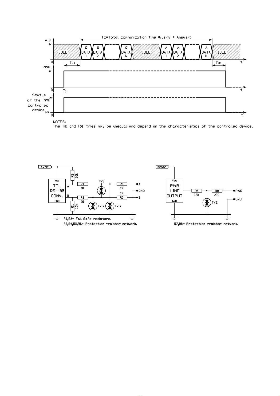
The following Figure 1 shows the correct timing diagram for a correct use of this signal.
Fig. 1: Timing diagram of the PWR line.
ERE S n.c. DC485USB: Instruction Manual Revision: 1.0
Page 5 of 7
As appears clearly the PWR signal must be activated before of the communication and must be disabled after its end.
Of course if the communication foresee a polling cycle of many peripherals it’s better to activate the PWR line before
the start of the polling cycle and disable it after its end, so that the communication will be not affected by dead times.
In the following Figure 2 is present the simplified schematic ofthe A, B and PWR lines to show the internal impedance.
Fig. 2 : Simplified schematics of A, B and PWR line.
4.0.3 GND line.
The GND (Ground) line is the common reference for both Aand Blines and for the PWR line. It is electrically
connected to the GND of the USB Port and must be connected to the ground line of the RS – 485 serial port of the
external device so that the reference of the two serial port is the same. This is particularly important if the distance
between the converter and the device is considerable, and if the negative pole of the remote device feeder is not
connected to earth. This line may be used to connect also the shield of the cable connecting it only on a side, to obtain
the maximum screening efficiency.
4.0.4 Connections to a remote device using the RS – 485 serial port.
The following Figure 3 shows the connection between the DC485USB Converter and a remote device using the RS –
485 serial port and the PWR line as remote switching control. In this case the connecting cable, eventually shielded if
the distance are considerably, must contain 4 wires: the Aand B lines, the PWR line and the common Ground
(GND) line. The shielding braid of the cable must be connected only on one side so that it is equipotential. In the
figure is clearly shown as the negative pole of the supply of the remote device is connected to the GND line of the
converter, to realise a common reference for the data lines. This reference point is normally, for obvious reasons of
electrical safety, connected to earth.
Fig. 3: Wiring of the DC485USB Converter and remote device.

ERE S n.c. DC485USB: Instruction Manual Revision: 1.0
Page 6 of 7
If the PWR signal is not used, the connecting cable may contains only 3 wires plus the shielding braid.
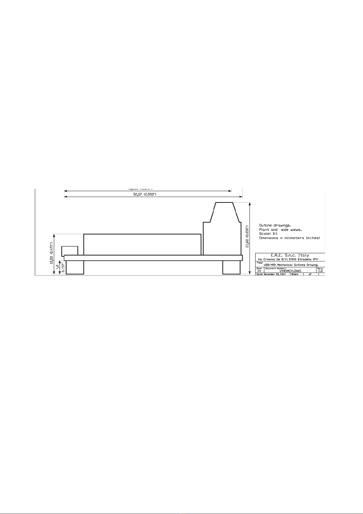
5.0 Mechanical characteristcs.
The following Figure 4 shows the mechanical outline of the DC485USB Converter. All dimensions are in millimeters
(inches).
ERE S n.c. DC485USB: Instruction Manual Revision: 1.0
Page 7 of 7
Table of contents


