ergoline ergometrics er 800S User manual

Operation Manual
ergometrics er800S
Art-Nr: 475.051 !Version: 05/02

Operation Manual for Bicycle Ergometer er800S
Printed in Germany.
We reserve the right of modifications due to technical development at any time and without prior notice.
Reprinting, translation and copying in any form - also in parts - is only permitted after prior written consent
by the manufacturer.
This Operation Manual is not registered for automatic update in case of possible alterations.
Information regarding the latest version is available from the manufacturer.
This Operation Manual Ergometer ergometrics 800S
Version: 05/02
is valid for following Software-Versions:
V3.3 / 9.3
ergoline GmbH
Lindenstraße 5
D-72475 Bitz
Tel.: +49 7431 98 94 - 0
Fax: +49 7431 98 94 - 127
e-mail: [email protected]
internet: http://www.ergoline.com
Version: 05/02 er800S Operation Manual
Art-Nr: 475.051


Version: 05/02 er800S Operation Manual
Art-No: 475.051

EC Declaration of Conformity ............................................................................... i
Table of Contents................................................................................................ iii
Foreword............................................................................................................. v
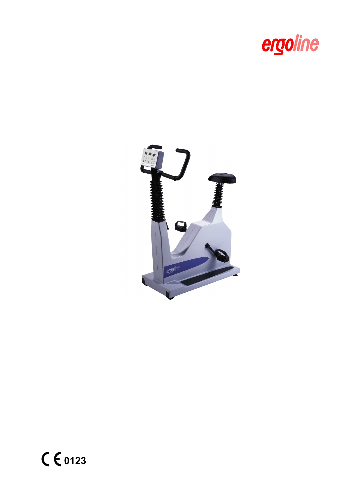
What the ergometrics er800S Offers................................................................... vi
1. Installation ......................................................................................................... 1
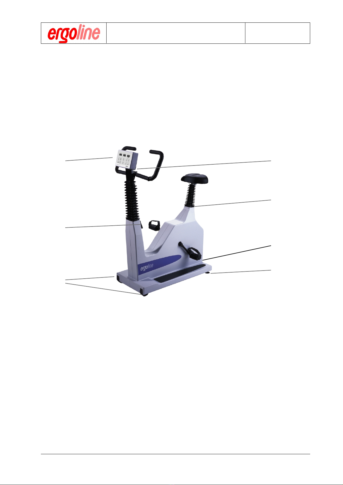
1.1 Features and Connections................................................................................... 1
1.2 Console............................................................................................................... 2
1.2.a Keypad ............................................................................................................... 2
1.3 Connectors and Interfaces ................................................................................... 3
1.3.a Power Connection ............................................................................................... 3
1.3.b Attaching a Pulse Meter, (e.g. Polar-Pacer) ......................................................... 3
1.3.c Signal Interface.................................................................................................... 4
1.4 Starting the Ergometer ........................................................................................ 5
2. Operation ........................................................................................................... 7
2.1 Your Helper - the Computer .................................................................................. 7
2.2 Control Panel ...................................................................................................... 8
2.2.a Parameters displayed on the Control Panel and their Meaning ............................ 8
3. Ergometric Process .......................................................................................... 9
3.1 Preparing the Patient........................................................................................... 9
3.2 Preparing of the Ergometer ............................................................................... 10
3.2.a Preparing an Automatic Ergometric Process ..................................................... 10
3.2.b Preparing a Manually Controlled Ergometry ....................................................... 10
3.3 Considerations for Control by ECG or PC ......................................................... 11
3.4 Starting the Ergometer ...................................................................................... 11
3.4.a Starting Automatic Operation............................................................................. 11
3.4.b Starting an ECG or PC Controlled Ergometry .................................................... 12
3.5 Process Flowcharts ........................................................................................... 12
3.5.a Automatically Controlled Ergometric Process .................................................... 12
3.5.b Manually Controlled Ergometric Process ........................................................... 13
4. Safety & Maintainance .................................................................................... 15
4.1 Safety ................................................................................................................ 15
4.2 Intended Use ..................................................................................................... 15
4.3 Basic Safety Comments .................................................................................... 15
4.4 Normative Notices ............................................................................................. 16
4.4.1 Notice for EMC (electromagnetic compatibility) ................................................. 16
4.5 Requirements for Operating Personnel .............................................................. 17
4.6 Safety and Device Protecting Features.............................................................. 17
4.7 Measurement Accuracy Verification ................................................................... 17
4.7.1 Load Unit Inspection .......................................................................................... 17
4.8 Cleaning ............................................................................................................ 17
4.8.a Cleaning the Unit ............................................................................................... 17
4.9 Identification plate, Labelling .............................................................................. 18
Version: 05/02 iii er800S Operation Manual
Art-Nr: 475.051
Table of Contents
Operation Manual Ergometer
Type er800S

er800S Operation Manual iv Version: 05/02
Art-Nr: 475.051
5. Configuration .................................................................................................. 19
5.1 General ............................................................................................................. 19
5.2 Setting the Load Algorithm ................................................................................ 19
5.2.a Linear Load Increment Program V 3.3 (3.3) ....................................................... 19
5.2.a.1 Linear Program Setup ....................................................................................... 20
5.2.b WHO Step Program V 9.3 (9.3) ......................................................................... 20
5.3 Setting an Individual Load Profile ....................................................................... 21
5.3.a Setting the Initial Load ....................................................................................... 21
5.3.b Setting the Load Increments .............................................................................. 21
5.3.c Setting the Pulse Limit ....................................................................................... 22
Appendix A: Interfaces ................................................................................... 23
A.1 Input and Output Pin Specifications.................................................................... 23
Ergometrics er800S: RS-232 Interface .............................................................. 24
Appendix B: HF Input ..................................................................................... 27
B.1 HF Return from ECG ......................................................................................... 27
B.2 Pulse Monitor .................................................................................................... 27
Appendix C: Service....................................................................................... 29
C.1 Calibrating the Analog I/O Signals ..................................................................... 29
C.1.a Calibrating the Analog Load Control Input .......................................................... 29
C.1.b Calibrating the Analog Load Output ................................................................... 29
C.2 Load Unit Calibration......................................................................................... 30
C.3 Service Connectors ........................................................................................... 30
Appendix D: Specifications ........................................................................... 31
D.1 Specifications ................................................................................................... 31
Operation Manual
Ergometer
Type er800S Table of Contents

Foreword:
We are pleased that you chose to purchase our computerized ergometer, ergometrics
er800S. This unit gives you and your patients the benefits of a new dimension in stress test
analysis and cardiovascular training.
The computerized ergometrics er800S ergometer has been specially designed with the
medical and ergonomic requirements in mind for well documented and monitored stress
testing and for cardiovascular training. Computer control makes fully automatic training a
simple process. Automatic operation can always be interrupted for manual intervention or
training can be entirely under manual control.
The possibility to connect the ergometer with heart rate monitoring devices means that steady-
state-pulse training can be carried out safely with a minimum of personnel.
A serial interface allows the unit to be connected to a computer system. This allows for excel-
lent control and documentation of the training as well as for remote control via an ECG for
stress testing. It also permits the ergometer to be integrated into a multi-station rehab-sys-
tem like „ergosoft".
This handbook is intended for the operator of the unit. It explains all the ergometer’s functions
in detail and in such a manner that operation of the unit can be learned through its use. This
manual can also be used as a reference.
We hope that you are successful in your work with the ergometrics er800S ergometer. We
always welcome your constructive remarks and improvement suggestions with regard to the
unit as well as to this handbook.
Your ergoline team,
GmbH
Lindenstraße 5
72475 Bitz
Germany
Tel: +49 7431 9894-0
Fax: +49 7431 9894-127
Attention !
This Operation Manual is a part of the unit in accordance with EN 60601-1:1990. It
should always be kept close to the unit. The necessary safety considerations, con-
forming to EC Guideline 93/42 EC are in chapter 4 of this manual.
Introduction
Operation Manual Ergometer
Type er800S
Version: 05/02 ver800S Operation Manual
Art-No: 475.051

What the ergometrics er800S Offers
The ergometrics er800S ergometer is a computer controlled, speed independent, bicycle
type ergometer which incorporates state-of-the-art technology. The ergometer conforms to
DIN 13405 and is certified by the Physikalisch Technischen Bundesanstalt (PTB).
The ergometer is speed independent within the range of 30 to 130 revolutions per minute
and load range between 25 and 999 Watts. Load max. tolerance is 3% (min. though of ±3
Watt).
Seat height, handlebar height and handlebar positioning are infinitely variable adjustable for
body heights between 1.20 m and 2.10 m.
The unit has connectors which allow it to interface with numerous other devices for compre-
hensive data and documentation services, e.g. ECG units, Spirometer, PCs, etc. These in-
terfaces are supported by the standard software. A linear load increment program or a WHO
conformant step load program may be selected for automatic ergometric operations. The
unit will automatically operate in Pulse-Steady-State-Training, with freely selectable heart
rate limit when a QRS signal is provided.
The ergometer is almost maintenance free due to its very solid construction. Inspections and
calibration that may become necessary are very simple to perform and can be done with a
minimum of time and material. Maintenance instructions are in the appendix of this manual.
Be sure to take notice of the preventive maintenance instructions in chapter 4 of this manual.
Operation Manual
Ergometer
Type er800S Introduction
er800S Operation Manual vi Version: 05/02
Art-Nr: 475.051

Version: 05/02 1er800S Operation Manual
Art-Nr: 475.051
Operation Manual Ergometer
Type er800S
Chapter 1: Installation
1.1 Features and Connections
1 power connector, fuse and main power switch
2 clamp handle for seat adjustment
3 clamp handle for handlebar height adjustment
4 clamp handle for handlebar angle adjustment
5 transport casters
6 control panel with keypad and LED displays
7 leveling feet for optimal stability
1
2
46
3
5
7

er800S Operation Manual 2Version: 05/02
Art-Nr: 475.051
Operation Manual
Ergometer
Type er800S Chapter 1: Installation
1.2 Control Panel
1.2.a Keypad
1 LED display for heart rate
2 LED display for RPM
3 LED display for power
4 manual power change in 5 Watt steps
3261
795
5 manual power change in 25 Watt steps
6 set base value for start load
7 set value for pulse limit
8 set base value for load change
9 cursor buttons for increase / decrease of values
10 start/stop switch for begin/end of load
11 pulse indicator
4
11
8
10

Version: 05/02 3er800S Operation Manual
Art-Nr: 475.051
Operation Manual Ergometer
Type er800S
Chapter 1: Installation
1.3 Connectors and Interfaces
1.3.a Power Connection
Note: When using an ergoline suction device it is convenient to connect the
unit’s power plug to one of the white outlets at the suction device. The
ergometer can then be turned on and off by using the main switch on the
suction device.
1.3.b Attaching a Pulse Meter, (e.g. Polar-Pacer)
Connect the Polar-Set’s receiver to the opto interface (J3). An
ear finger clip or the QRS-trigger of an ECG unit can also be
connected here.
1. Make sure that the power switch is in the
"off" (not depressed) position.
2. Connect the unit´s power plug to a 230V
outlet with the supplied power cord.

er800S Operation Manual 4Version: 05/02
Art-Nr: 475.051
Operation Manual
Ergometer
Type er800S Chapter 1: Installation
1.3.c Signal Interface
Analog interface for analog control
and analog data transfer to an
ECG
Digital RS-232 interface
connector for PC or ECG
Note: Interface pin descriptions and related technical data are in the appendix
to this manual.

Version: 05/02 5er800S Operation Manual
Art-Nr: 475.051
Operation Manual Ergometer
Type er800S
Chapter 1: Installation
1.4 Starting the Ergometer
Turn on the unit by pressing the main power switch.
The unit will subsequently execute a self-test. During this time 888 will be displayed.
Upon termination of the self-test the indicators will appear as below:
0 0 00 0 0 0 0 0
Main power switch

er800S Operation Manual 6Version: 05/02
Art-Nr: 475.051
Operation Manual
Ergometer
Type er800S Chapter 1: Installation

Operation Manual Ergometer
Type er800S
Chapter 2: Operation
Version: 05/02 7er800S Operation Manual
Art-Nr: 475.051
2.1 Your Helper - the Computer
The bicycle type ergometer ergometrics er800S was designed as a training ergometer
with which cardiovascular training can be carried out
simply - quickly - accurately - safely.
To this end, the computer is an indispensable aid. The computer can carry out a very
accurate pulse-steady-state-training as well as training with linear load increments or WHO
compliant load steps. The schematic below shows how versatile the unit is.
digital control from a PC or ECG
The ergometer can be controlled by a PC or ECG via the
integrated RS-232 interface. Multiple station systems for re-
habilitation can also be created.
analog control by an ECG
The ergometer can be controlled by an ECG via the analog
interface. Current data from the ergometer can be requested
over this interface.
external control
Training with WHO compliant load
steps
Load steps, compliant to the WHO table, can
also be set on the ergometer. The duration
of the load steps is then taken from the table
as specified by the load steps that were
selected.
Pulse-Steady-State-Training
By connecting a pulse probe, e.g. a Polar-
Pacer, the unit can independently carry out
pulse-steady-state-training. The heart rate
selected will be maintained throughout the
training session.
Training with linear load
increments
By setting the linear load increments the load
will be increased in accordance with the
selected linear steps over the period of 1
minute.
manual intervention
It is always possible to intervene manually in
the running program to increase or decrease
the load or alter other parameters.
internal control

Operation Manual
Ergometer
Type er800S Chapter 2: Operation
er800S Operation Manual 8Version: 05/02
Art-Nr: 475.051
2.2 Control Panel
2.2.a Parameters Displayed on the Control Panel and their Meaning
Power in Watts
This indicator displays the current power rating in Watts during an ergometric program.
Prior to beginning a load program (with the START key) this indicator can also display the
start load „Po“ in Watts or the load increments in W/min.
Press the appropriate red labelled key to display one of these values. The LED for the key
selected will blink and the current setting for this parameter will be displayed. As long as
the setting is selected, as indicated by the blinking LED, it may be altered by using the red
labelled „Up / Down“ keys. (Refer also to Chapter 5)
Revolutions per Minute (RPM)
This indicator displays the current RPM value during an ergometric program. The indicator
will begin to blink with every load change and display the physiologically optimal RPM
value expected of the test subject for the established load. If this RPM value can be
roughly maintained, the heart rate increase will be minimized (pulse sum curve). Basically,
the patient should select an RPM value that he feels comfortable with as the load on the
ergometer is independent from the pedal speed.
Heart Rate in Beats/Min
The current pulse rate is displayed here provided that a POLAR chest belt is attached or
there is a QRS connection to an ECG. By pressing the appropriate red labelled key prior
to beginning an ergometric program the established heart rate value for pulse-steady-
state-training can be displayed. The setting may be altered by using the red labelled „Up
/ Down“ arrow keys as long as this value is selected (as indicated by the blinking LED in
this key). (Refer also to Chapter 5)
Note: The ergometer automatically switches to pulse-steady-state-training
whenever it receives a heart rate from a pulse probe such as an ear/
finger clip or from a QRS connection to an ECG.

Operation Manual Ergometer
Type er800S
Chapter 3: Ergometric Process
Version: 05/02 9er800S Operation Manual
Art-Nr: 475.051
3.1 Preparing the Patient
1. Have the patient take his place on the saddle.
2. Position the saddle so that an angle of approx. 170 degrees exists between the
extended axis of the upper body and the thigh when the pedal is at its lowest
position. Ask the patient to stand on the pedals while you adjust the saddle posi-
tion. Saddle height is adjusted by loosening the saddle clamp screw and moving
the saddle to the correct position.
3. Move the handlebar to a position so that the test subject can comfortably sit up-
right. To do this, loosen the handlebar height clamp handle and adjust appropri-
ately. Next you can adjust the angle of the handlebar by loosening the handlebar
angle clamp handle.
4. Check to see that all the adjustment clamps are tightened. (Do not tighten these
with extreme force)
Clamp handle for
handlebar angle
Clamp handle for
handlebar height
Clamp handle for
seat height

Operation Manual
Ergometer
Type er800S Chapter 3: Ergometric Process
er800S Operation Manual 10 Version: 05/02
Art-Nr: 475.051
3.2 Preparing the Ergometer
3.2.a Preparing an Automatic Ergometric Process
1. Program the desired parameters by first pressing the appropriate red labelled key,
„Po“, „P (W/MIN)“ or „HR“. The corresponding LED will blink while you establish the
desired value by using the red labelled arrow keys. (Refer also to Chapter 5)
Note: Setting a heart rate value only makes sense when pulse-steady-state-
training is to be performed. To do this, it is absolutely necessary to pro-
vide the ergometer with a heart rate from a pulse monitor or a QRS trig-
ger from an ECG.
3.2.b Preparing a Manually Controlled Ergometry
There are two methods for manual operation of the ergometer.
1. Set all parameters to „000“. Proceed as described in section 3.2.a and press the
red labelled „Down“ key until the value reaches „000“. The LED in the correspond-
ing key will turn off because, at this point, the memory is empty.
Now start the ergometry by pressing the „START/STOP“ key. The ergometer will
switch the initial load to 20W and the patient can begin to pedal. Subsequent
control is determined by the operator and must be entered by using the keys „+/-
25 Watt" or „+/- 5 Watt".
2. Set the value for the initial load as described under 3.2.a. The other parameters
may be disregarded. Start the ergometry by pressing the „START/STOP“ key.
Let the patient begin to pedal. As soon as the patient starts, press key „START/
STOP“ again - the automatic load program will now stop. Now the load control is
up to the operator and may be entered by using the keys „+/- 25Watt“ or „+/- 5Watt“.
3. Pressing the key "START/STOP" again, will terminate the load program.

Operation Manual Ergometer
Type er800S
Chapter 3: Ergometric Process
Version: 05/02 11 er800S Operation Manual
Art-Nr: 475.051
Note: The target RPM value is a recommendation, not a requirement. The er-
gometerprovidesthispsychologicallyoptimalRPMvaluefortheset load
valuesothat theheartrateremainsataminimum.Basically,however,the
test subject should pedal at the rate which is most comfortable for him.
Theload on the ergometerisindependent from thepedalspeed.
3.3 Considerations for Control by ECG or PC
The ergometrics er800S ergometer can only be controlled by an ECG or a PC if the
ECG or the PC supports the interface protocol of the ergometrics er800S. Ask your
ECG or PC program supplier for details.
.The parameter “START LOAD”, “LOAD ALTERATION” and “HR LIMIT” have
besetto“000” (or to the minimal value) forPCoperation(seheChap.3.2.a).The
LEDinthecorresponding key will thenbeturnedoff.
3.4 Starting the Ergometer
3.4.a Starting Automatic Operation
1. Check toseeif all the parametersarecorrectly entered.
2. Start theergometricprocedure by pressingthe„START/STOP“ key.
3. Let thepatient begin topedal.
Thedisplaywillthenshowthecurrentload(initialload). TheRPMdisplaywillblink
for10sec. while displaying thegoalRPMvalue.

Operation Manual
Ergometer
Type er800S Chapter 3: Ergometric Process
er800S Operation Manual 12 Version: 05/02
Art-Nr: 475.051
Ending the ergometry
The ergometry will end when the patient ceases to pedal and subsequently the „START/STOP“
key is pressed.
Advancing to the nth load increment
The load will be increased by the programmed value „P (W/MIN)“.
Terminating the load program
A single press of the „START/STOP“ key will terminate the loading program. That is, the load
will no longer be increased. If the „START/STOP“ key is pressed again, the load program will
continue to proceed normally.
Possible Parameter Alterations
Prior to beginning an ergometric session you can alter any parameter for a specific ergometry.
See 3.2.a
Application of the initial load Po
The load program will begin and the initial load Po will be applied.
Advancing to the second load increment
The load will be increased by the programmed value „P (W/MIN)“.
Advancing to the first load increment
The load will be increased by the programmed value „P (W/MIN)“.
Ergometry Start
Press the „START“ key to begin the ergometric session.
3.4.b Starting an ECG or PC Controlled Ergometry
Start the ergometric program on your ECG or PC in accordance with the correspond-
ing instructions. After a successful start the patient should begin to pedal.
3.5 Process Flowcharts
Note: This ergometric process flow description is only valid for use of the ergo-
meter under its own internal control or manual control by the operator.
When control is exercised by an ECG or PC refer to the documentation
for those devices.
3.5.a Automatically Controlled Ergometric Process
Table of contents
Other ergoline Fitness Equipment manuals
Popular Fitness Equipment manuals by other brands

Gymrex
Gymrex GR-SI50 user manual

FREE MOTION
FREE MOTION EPIC STRENGHT GZFI8013.3 owner's manual

Tuff stuff
Tuff stuff BA-704 owner's manual

Life Gear
Life Gear 76200 owner's manual

Powerline
Powerline BSGLPX installation instructions

Life Span
Life Span Contour Pro Studio Aluminium Reformer Pilates Bed... user manual