ergoline ergoselect 1000 User manual

Manual
ergoselect 1000
Couch Ergometer
Operator's Manual
2010000070000 • Version 06/2009 • English

This manual was written with the utmost care. Should you still nd details that do not correspond with the system,
please let us know and we will correct the issue as soon as possible.
We reserve the right to modify the design and technical features of the device and are not bound by the information and
illustrations provided in this manual.
All trademarks appearing in this document are trademarks of their respective owners. Their protection is acknowledged.
No part of this manual may be reprinted, translated or reproduced without the manufacturer's written permission.
This manual is not subject to any change order service. Please contact the manufacturer for the latest document
revision.
ergoline GmbH
Lindenstraße 5
72475 Bitz
Germany
Tel.: +49-(0) 7431 98 94 - 0
Fax: +49-(0) 7431 98 94 - 128
e-mail: [email protected]
http: www.ergoline.com
Printed in Germany

- 3 -
Declaration of Conformity . . . . . . . . . . . . . . . . . . . . . . . . . . . . . 5
General Information . . . . . . . . . . . . . . . . . . . . . . . . . . . . . . . . 6
Safety Information . . . . . . . . . . . . . . . . . . . . . . . . . . . . . . . . 7
Intended Use . . . . . . . . . . . . . . . . . . . . . . . . . . . . . . . . . . . 8
Setup and Mains Connection . . . . . . . . . . . . . . . . . . . . . . . . . . .10
Controls and Indicators . . . . . . . . . . . . . . . . . . . . . . . . . . . . . . . . . . . . . . . . . . 10
Ergometer Setup . . . . . . . . . . . . . . . . . . . . . . . . . . . . . . . . . . . . . . . . . . . . . 10
Connecting the Power Cord. . . . . . . . . . . . . . . . . . . . . . . . . . . . . . . . . . . . . . . . 12
Connecting the ECG Cable . . . . . . . . . . . . . . . . . . . . . . . . . . . . . . . . . . . . . . . . 12
Preparing the Patient . . . . . . . . . . . . . . . . . . . . . . . . . . . . . . 13
Adjusting the Couch . . . . . . . . . . . . . . . . . . . . . . . . . . . . . . . . . . . . . . . . . . . 13
Preparing the Couch with the Patient . . . . . . . . . . . . . . . . . . . . . . . . . . . . . . . . . . 13
Preparing the Patient for Blood Pressure Measurements. . . . . . . . . . . . . . 14
Checking the Cu Tubing . . . . . . . . . . . . . . . . . . . . . . . . . . . . . . . . . . . . . . . . . 15
Operation . . . . . . . . . . . . . . . . . . . . . . . . . . . . . . . . . . . . 16
Control terminal P. . . . . . . . . . . . . . . . . . . . . . . . . . . . . . . . 16
Turning the System On . . . . . . . . . . . . . . . . . . . . . . . . . . . . . . . . . . . . . . . . . . 16
Operating Modes with Control Terminal P . . . . . . . . . . . . . . . . . . . . . . . . . . . . . . . . 17
PC Mode. . . . . . . . . . . . . . . . . . . . . . . . . . . . . . . . . . . . . . . . . . . . . . . . . . 18
Ergometry . . . . . . . . . . . . . . . . . . . . . . . . . . . . . . . . . . . . . . . . . . . . . . . . . 19
Manual . . . . . . . . . . . . . . . . . . . . . . . . . . . . . . . . . . . . . . . . . . . . . . . . . . 21
Settings with Control Terminal P . . . . . . . . . . . . . . . . . . . . . . . . . . . . . . . . . . . . . 22
Control Terminal K . . . . . . . . . . . . . . . . . . . . . . . . . . . . . . . 28
Turning the System On . . . . . . . . . . . . . . . . . . . . . . . . . . . . . . . . . . . . . . . . . . 28
Operating Modes with Control Terminal K . . . . . . . . . . . . . . . . . . . . . . . . . . . . . . . . 29
Speed readout. . . . . . . . . . . . . . . . . . . . . . . . . . . . . . . . . . . . . . . . . . . . . . . 29
PC Mode. . . . . . . . . . . . . . . . . . . . . . . . . . . . . . . . . . . . . . . . . . . . . . . . . . 30
Reha Ergometer in PC Mode . . . . . . . . . . . . . . . . . . . . . . . . . . . . . . . . . . . . . . . 31
Ergometry . . . . . . . . . . . . . . . . . . . . . . . . . . . . . . . . . . . . . . . . . . . . . . . . . 32
Manual . . . . . . . . . . . . . . . . . . . . . . . . . . . . . . . . . . . . . . . . . . . . . . . . . . 34
Training . . . . . . . . . . . . . . . . . . . . . . . . . . . . . . . . . . . . . . . . . . . . . . . . . . 35
Training with Chip Card. . . . . . . . . . . . . . . . . . . . . . . . . . . . . . . . . . . . . . . . . . 36
Settings for Control Terminals K . . . . . . . . . . . . . . . . . . . . . . . . . . . . . . . . . . . . . 38
Cleaning, Maintenance, Disposal . . . . . . . . . . . . . . . . . . . . . . . . . 45
Technical Specications . . . . . . . . . . . . . . . . . . . . . . . . . . . . . 48
Elektromagnetische Verträglichkeit EN 60601-1-2 . . . . . . . . . . . . . . . . 52
Contents

- 4 -

- 5 -
DeClaration of Conformity

- 6 -
General information
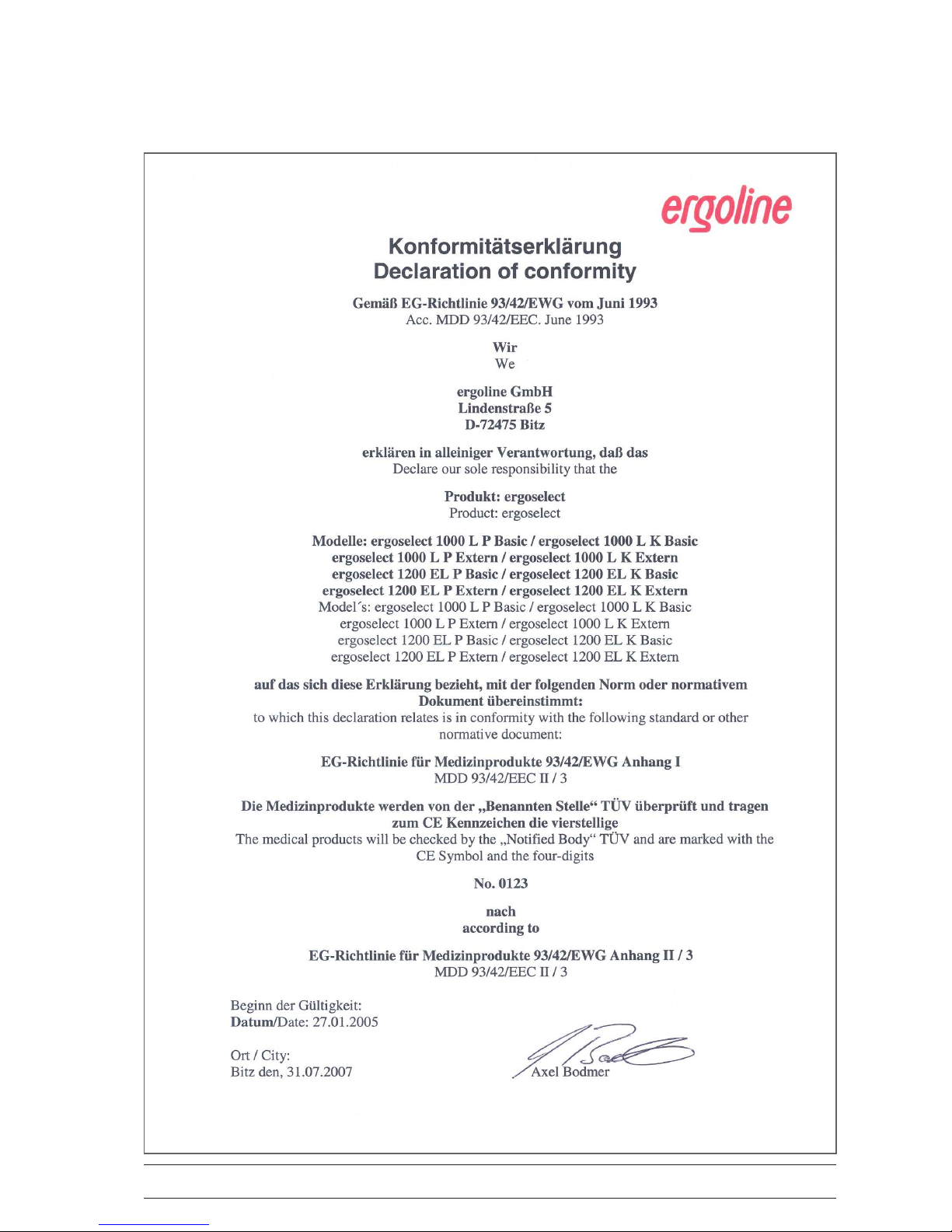
• TheproductergoselectbearstheCEmarkingCE‑0123
(NotiedBody:TÜV),indicatingitscompliancewith
theprovisionsoftheCouncilDirective93/42/EEC
aboutmedicaldevicesandfulllstheessential
requirementsofAnnexIofthisdirective.
TheCEmarkingcoversonlytheaccessorieslistedin
theOrderInformationchapter.
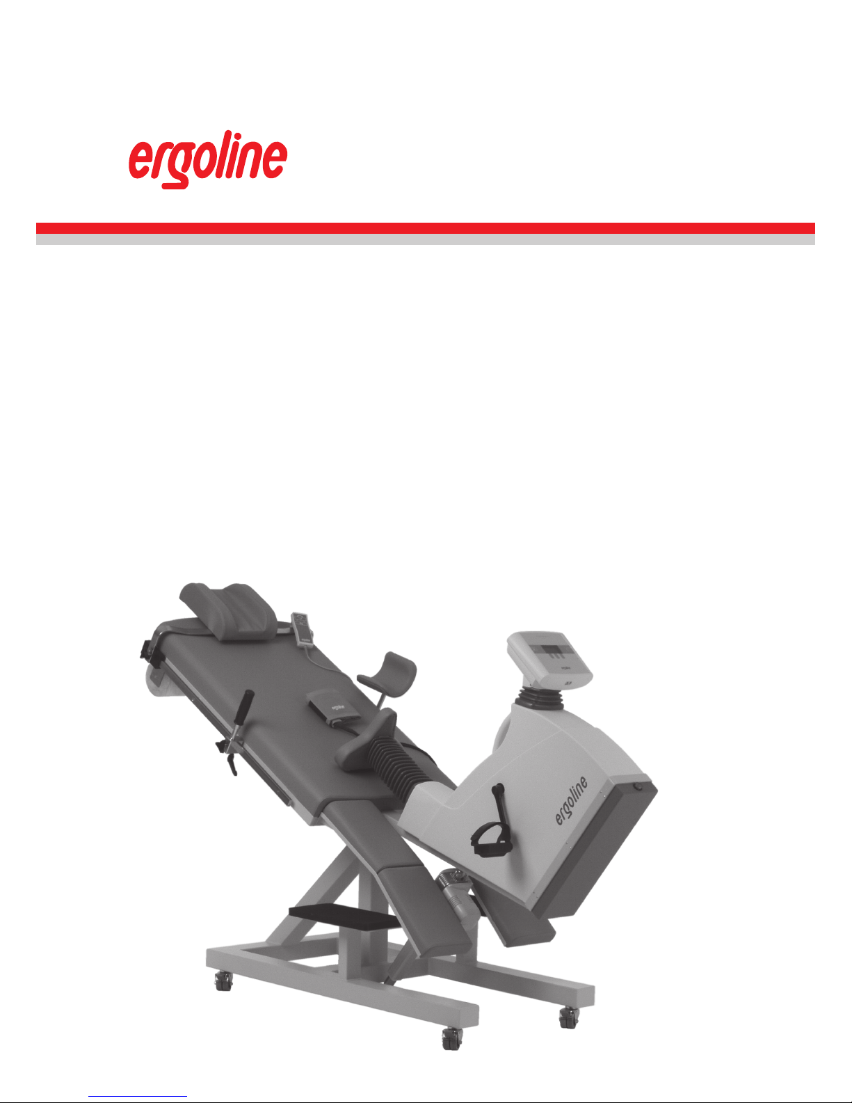
TheergometerisanMDDclassIIaproduct.
• Thedevicefulllstherequirementsofstandard
EN60601‑1"MedicalElectricalEquipment,Part1:
GeneralRequirementsforSafety"aswellasthe
interferenceprotectionrequirementsofstandard
EN60601‑1‑2"ElectromagneticCompatibility–
MedicalElectricalDevices".
Theradio‑interferenceemittedbythisproductis
withinthelimitsspeciedinEN55011,classB.
• Thismanualisanintegralpartoftheequipment.It
shouldbeavailabletotheequipmentoperatoratall
times.Closeobservanceoftheinformationgivenin
themanualisaprerequisiteforproperdeviceperfor‑
manceandcorrectoperationandensurespatientand
operatorsafety.Pleasenotethatinformationpertinent
toseveralchaptersisgivenonlyonce.Therefore,read
themanualoncecarefullyinitsentirety.
• Thesymbols mean:
Consultaccompanyingdocuments.
Itindicatespointswhichareofparticularimportance
intheoperationofthedevice.
• Observanceofthesafetyinformationprotectsfrom
injuriesandpreventsinappropriateuseofthedevice.
Allequipmentusersandpersonsresponsiblefor
assembly,maintenance,inspectionandrepairofthe
devicemustreadandunderstandthecontentofthis
manual,beforeusingorworkonit.
Paragraphswithspecialsymbolsareofparticular
importance.
• Ifunauthorizedindividualsopenthecontrolterminal,
damagingthecalibrationsticker,anywarrantyclaim
shallbecomevoid.
• Thismanualreectstheequipmentspecications
andapplicablesafetystandardsvalidatthetimeof
printing.Allrightsarereservedfordevices,circuits,
techniques,softwareprograms,andnamesappearing
inthismanual.
• OnrequestERGOLINEwillprovideaFieldService
Manual.
• TheERGOLINEqualitymanagementsystemcomplies
withthestandardsISO9001:2000andENISO13485:
2003.
• Thesafetyinformationgiveninthismanualisclassi‑
edasfollows:
• Toensurepatientsafety,thespeciedmeasuringac‑
curacy,andinterference‑freeoperation,werecom‑
mendusingonlyoriginalERGOLINEaccessories.The
userisresponsibleifnon‑ERGOLINEaccessoriesare
used.
• ERGOLINEisresponsibleforthesafety,reliability,and
performanceoftheequipment,onlyif
‑ modicationsandrepairarecarriedoutby
ergolineGmbHorbyanorganizationexpressly
authorizedbyergolineGmbH
‑ theequipmentisusedinaccordancewiththe
instructionsgiveninthisoperator'smanual.
ergoline GmbH
Lindenstrasse 5
72475 Bitz
Germany
Phone:+49-(0)-7431 - 9894 -0
Fax: +49-(0)-7431 - 9894 -128
http: www.ergoline.com / www.ergoline.eu
Danger
indicates an imminent hazard. If not avoided, the hazard will
result in death or serious injury.
Caution
indicates a potential hazard. If not avoided, the hazard may
result in minor injury and/or product/property damage.
Warning
indicates a hazard. If not avoided, the hazard may result in minor
injury and/or product/property damage.

- 7 -
Danger
• Explosion Hazard •
The device is not designed for use in areas where an explosion
hazard may occur.
Explosion hazards may result from the use of ammable anes-
thetics, skin cleansing agents or disinfectants.
Warning
• Patient Hazard, Equipment Damage •
Do not expose the ergoselect to direct sunlight to prevent system
components from reaching inadmissible high temperatures.
Do NOT use the ergoselect outdoors (medical device). Furthermore
the device has no additional protection against the ingress of hu-
midity. Humidity inside the device may cause equipment malfunc-
tions and increases the risk of an electric shock.
Additionally, the device should not be operated in the vicinity of
electric power plants, because they may impair equipment func-
tions.
The ergoselect ergometer may only be used in combination with
accessories approved by ergoline GmbH.
• Risk to Persons •
Before using the ergometer, the operator must ascertain that it is
in correct working order and operating condition. The cables and
connectors, in particular, must be checked for signs of damage.
Damaged parts must be replaced immediately, before use.
• Equipment Malfunction •
Only the special shielded cables supplied by ERGOLINE may be
used to connect the device to other pieces of equipment.
• Equipment Malfunction •
Cellular telephones may not be used in the immediate vicinity
of the ergometer, because they might interfere with the proper
functioning of the ergometer.
Electromagnetic interference most probably exists when the watt
reading is unstable. If the displayed value changes frequently even
though the speed is above 30 RPM, this may be due to electro-
magnetic interference.
Warning
• Shock Hazard •
When the ergometer is connected to other equipment or if a medi-
cal system is created, it must be ensured that the added leakage
currents do not present a hazard.
In case of questions, please contact your ERGOLINE dealer or the
ergoline GmbH Service Department.
For use, the ergometer must always be connected to electric
installations that fulll the local requirements.
• Patient Hazard •
The German Medical Device Operator Ordinance (MPBetreibV, § 5)
demands that users
• must be trained in the use of the ergometer
• must be familiar with the routines for handling and
assembly of the ergometer
• must be familiar with and observe the safety rules and regu-
lations for operation of this type of equipment
• must be informed about any other pertinent rules and regu-
lations (e.g. safety features)
• must be informed about the potential hazards arising from
the use of this type of equipment.
safety information
Hint
Removing the power cord results in complete disconnection from
mains (all poles)..
Danger
Additionalequipmentconnectedtomedicalelectrical
equipmentmustcomplywiththerespectiveIECorISO
standards(e.g.IEC60950fordataprocessingequipment).
Furthermoreallcongurationsshallcomplywiththere‑
quirementsformedicalelectricalsystems(seeIEC60601‑
1‑1orclause16ofthe3Ed.ofIEC60601‑1,respectively).
Anybodyconnectingadditionalequipmenttomedical
electricalequipmentconguresamedicalsystemandis
thereforeresponsiblethatthesystemcomplieswiththe
requirementsformedicalelectricalsystems.Attentionis
drawntothefactthatlocallawstakepriorityoverthe
abovementionedrequirements.Ifindoubt,consultyour
localrepresentativeorthetechnicalservicedepartment.
• IEC60601‑1+Al+A2:1995:6.8.2.c,19.2.b,19.2.c,
• IEC60601‑1:2005:7.9.2.5,8.1,16.2.d,
• MDD93142lEEC:AnnexIclause13.6.c

- 8 -
safety information for
non‑invasive BlooD Pressure
measurement
Warning
• Patient Hazard •
Do not take blood pressure measurements with a cu on pa-
tients suering from sickle cell anemia or where skin lesions are
likely to occur.
The cu may cause hematomas in patients with severe blood
coagulation disease. In these instances, the user must take a
decision for or against automatic blood pressure measurements.
Caution
• Compromised Measuring Accuracy •
Arrhythmias occurring frequently during a measurement may
compromise the accuracy of the measurement.
In certain cases, a valid measurement will not be possible.
Electromagnetic elds are also capable of impairing the measur-
ing accuracy.
Note
• The blood pressure module and the approved accessories
are debrillation-proof and may remain attached to the
patient during debrillation.
• If the cu pressure exceeds the maximum value of
300 mmHg during ination, the ination procedure will be
aborted and the cu deated.
As a redundant safety precaution, the cu is immediately
deated when the cu pressure exceeds 320 mmHg.
You can check the proper functioning of this safety precau-
tion by abruptly bending your arm while the cu is being
inated, causing a brief overpressure in the cu. The cu
must deate immediately.
• Measurements that did not yield a valid measurement will
not be repeated during the exercise test.
• If the ination phase takes longer than 40 seconds or if an
adequate pressure does not build up in the cu within a
reasonable period of time, the measurement will be aborted
and the cu deated.
• If a valid measurement cannot be completed within
120 seconds, the measurement will be aborted and the cu
deated.
• If the cu pressure remains constant for some time, the
measurement will also be aborted and the cu deated.
intenDeD use
Theergoselectisacomputer‑controlledmedicalergometer.
Atpedalspeedsbetween30and130RPMandloads
between6and999watt,theergometeroperatesindepen‑
dentofthepedalspeed.
Thespeed‑independentrangeisshownintheAppendix
(TechnicalSpecications).
Theergoselectergometermayonlybeusedinexercise
testingaswellasforrehabilitationofcardiacandcardio‑
vascularpatientsaccordingtotheinstructionsgivenin
thismanual.Iftheergometerisusedforotherpurposes,
themanufacturercannotbeheldliableforpersonalinju‑
riesorpropertydamageresultingfromtheunintendeduse
oftheequipment.
BioComPatiBility
Thepartsoftheproductdescribedinthismanual,includ‑
ingallaccessoriesthatcomeincontactwiththepatient
duringtheintendeduse,fulllthebiocompatibility
requirementsoftheapplicablestandardsifappliedas
intended.
Ifyouhavequestionsinthismatter,pleasecontact
ERGOLINEorarepresentative.
aPPliCaBle laws, reGulations anD
DireCtives
• 93/42/EEC(MedicalDeviceDirectiveoftheEU)
• 89/336/EEC(ElectromagneticCompatibilityDirective
oftheEU)
• EN1060‑1Non‑invasivesphygmomanometers,Part1:
Generalrequirements
• EN1060‑3Non‑invasivesphygmomanometers,Part3:
Supplementaryrequirementsforelectro‑mechanical
bloodpressuremeasuringsystems

- 9 -
Additionalequipmentconnectedtomedicalelectrical
equipmentmustcomplywiththerespectiveIECorISO
standards(e.g.IEC60950fordataprocessingequipment).
Furthermoreallcongurationsshallcomplywiththere‑
quirementsformedicalelectricalsystems(seeIEC60601‑
1‑1orclause16ofthe3Ed.ofIEC60601‑1,respectively).
Anybodyconnectingadditionalequipmenttomedical
electricalequipmentconguresamedicalsystemandis
thereforeresponsiblethatthesystemcomplieswiththe
requirementsformedicalelectricalsystems.Attentionis
drawntothefactthatlocallawstakepriorityoverthe
abovementionedrequirements.Ifindoubt,consultyour
localrepresentativeorthetechnicalservicedepartment.“
(Standard/directivereferences:
· IEC60601‑1+Al+A2:1995:6.8.2.c,19.2.b,19.2.c,
· IEC60601‑1:2005:7.9.2.5,8.1,16.2.d,
· MDD93142lEEC:AnnexIclause13.6.c

- 10 -
Setup and MainS ConneCtion
ControlS and indiCatorS
1 Clamping lever for head rest adjustment
2 Arm rest for blood pressure measurement
(right or left; on systems with automatic blood
pressure measurement only)
3 Handgrip (mounting and dismounting aid)
4 Speed indication for patient
5 Control terminal (model P or model K)
6 Power switch (green button)
7 Connectors for power cord and connection cables
8 Leg rest (option)
9 Castors, locking
10 Tissue roll
11 Remote control for couch and saddle adjustment
12 Connection for blood pressure cuff on either side of
the couch (on systems with automatic blood pres-
sure measurement only)
13 Type plate
14 Footboard
ergoMeter Setup
The ergoselect 1000 is mounted on a wooden pallet for
shipment.
You need a wrench (SW 17) or a ratchet and the corre-
sponding socket to detach the ergometer from the pallet
and for all other mounting operations described below.
Mounting the CaStorS
The four castors are mounted to the base plate with the
enclosed screws.
ergoselect 1000 - controls, connections and indicators
Caution
• Equipment Damage •
Avoid strong vibrations of the ergometer during transport.
• Patient Hazard / Equipment Damage •
During assembly, the ergometer must be disconnected from the
power line.

- 11 -
Mounting the aCCeSSorieS
• Introducethearmrestholderintotherightorleft
guide rail and secure in the desired position (1)
- on systems with blood pressure module only.
• Mountthelegrest(2)(option).
• Mountthetissuerollholderandinsertatissueroll
(3).
• Connectthebloodpressurecuffontherightorleft
side of the couch (4)
- on systems with blood pressure module only:
Connect the microphone at (1).
Slip the cuff tubing onto the connection sleeve (2)
and make sure that it locks properly into place.
To disconnect the tubing, push the knurled sleeve
backward.
Mounting the accessories
connecting the blood pressure cuff
Caution
• Equipment Damage •
When your couch ergometer has a separate control terminal,
route the connection cable to this terminal such that it does not
present a stumbling hazard.
Additionally, the control terminal must be protected from falling
down.

- 12 -
ConneCting the power Cord
The connection panel is located on the back of the drive
unit.
• Plugthepowercordintosocket(a)andusethesup-
plied lock (b) to secure it against disconnection.
• Usingthestrainreliefsupplied,screwthecableto
the metal frame.
ConneCting the eCg Cable
ergoselect ergometers can be connected to electrocar-
diographs and PC-based ECG systems of most manufac-
turers.
Different connection cables are available to support
different communication modes (digital, analog, remote
start, etc.).
The appropriate cable is plugged into the corresponding
port on the connection panel (Port 1, Port 3 or Analog)
and secured with the strain relief.
Caution
• Equipment Damage •
Before connecting the ergometer to the power line, check that
the line voltage corresponds to the ratings on the type plate.
The type plate is located on the back of the ergometer, at the
bottom.
connection panel
a Power input
b Lock
c Digital connection
(remote control by PC or ECG recorder
+ remote start pulse for ECG recorder)
d Service port
PC connector for software update
e Digital port
(remote control by PC or ECG recorder
+ remote start pulse for ECG recorder)
(compatible with ER 800/900)
f Analog port
remote control by ECG recorder
(compatible with ER 800/900)
g Service port
(to be used by authorized service personnel only)
Hint
• disconnection •
Removing the power cord results in complete disconnection from
mains (all poles).
• connecting cables •
Only use connecting cables released by ergoline.
Danger
• Patient Hazard •
To insure a safe connection to the protective ground system,
power cords of type „hospital only“ or „hospital grade“ have to
be used!

- 13 -
preparing the patient
adjuSting the CouCh
Saddle and couch are adjusted with the remote control
(see illustration at right):
Keys 2: longitudinal tilt adjustment (0 to 45 °)
Keys 3: saddle adjustment
The green indicator (1) is illuminated during activation of
any of the keys.
The movement will stop automatically when the final
position is reached. The movement will also stop, when
two control keys for one of the motors are pressed at the
same time.
preparing the CouCh with the patient
Before the patient can lie down on the couch, the er-
gometer must be prepared as follows:
• Retractthesaddlealltheway.
• Adjustthelongitudinaltilttoapprox.45°toallow
the patient to mount the couch easily.
• Ifalegrestisinstalled,removeitfromtheside
where the patient will mount the couch.
• Askyourpatienttoliedownonthecouch.
• Ifpedalshoesareinstalled,adjustthemtothe
patient's shoe size and strap the feet to the pedal
shoes with the Velcro loops.
• Reinstallthelegrest.
With the pedal in its lower position, there should be a
10°anglebetweentheaxisformedbytheupperbody
and the thigh:
• Adjustthesaddleuntilthisangleisachieved.
• Adjusttheheadrestuntilincontactwiththeshoul-
der, when the head is placed on the head rest.
Caution
• Patient Hazard •
Do not use the ergometer unless the brakes on all four wheels
are locked.
Otherwise the ergometer may move sideways, particularly when
the patient mounts the couch, and persons present could get
caught between the couch and other equipment or the wall.
• Patient Hazard •
Use only the handgrip at the drive unit as an aid in mounting and
dismounting the ergometer.
Do not allow patients to place their full weight on the arm
rest (for blood pressure measurements) or to use it as an aid in
mounting and dismounting the ergometer.
reMote control
1 green indicator (is illuminated while a key is pressed)
2 press to adjust the longitudinal tilt (0 - 45°)
3 press to adjust the saddle height
Note
• Tightentheclampingleversonlyasfarasnecessary,NOT
with maximum force.
• Lubricatetheclampingleverthreadsquarterlyatminimum,
using a suitable lubricant (e.g. OKS470).

- 14 -
PreParinG the Patient for BlooD
Pressure measurements
Cuff size
Alwayschoosethecusizesuitableforthepatient'sarm.
Themaximumarmcircumferenceisindicatedonthecu.
miCroPhone Position
Beforeapplyingthecu,checkthepositionofthemicro‑
phoneinsidetheredpocket(ontheinsideofthecu):
Whenthemicrophoneisinsidethepocket,itsmetal side
must face the arm.
aPPlyinG the Cuff
Thecenterofthemicrophonemustbelocatedexactly
onthebrachial artery.Locatethearterybypalpation,if
required.Thered tabidentiesthepositionofthemicro‑
phone.
Theaccurateplacementofthemicrophoneistheprimary
conditionforreliablepressuremeasurementduringexer‑
cisetests.
Thecumustbeapplieddirectlyontheskin,itmaynot
beappliedontopofclothing,paper,etc.Applythecu
approx.2 cm above the bend of theelbow.Thecu
shouldbetight,butitshouldnotconstrictbloodvessels.
Thecumay not moveduringtheexercisetest.
CorreCt miCrophone position
Wrong Cuff size
miCrophone plaCement on the artery
CorreCt Cuff size

- 15 -
CorreCt Cuff position (tab)
Caution
• Patient Hazard •
Apply the cu directly on the skin. Make sure that rolled up
sleeves do not impede blood circulation in the upper arm.
Loose cus will cause erroneous measurements; overtight cus
may constrict blood vessels or cause skin lesions and hemato-
mas.
• Incorrect Measurements •
A loose cu would degrade the accuracy of the measurement.
Therefore, the computer aborts the measurement, if a minimum
pressure is not attained within a few seconds.
Warning
• Patient Hazard •
If, by accident, an excessive pressure builds up inside the cu ,
either remove the cu immediately from the arm or disconnect
the cu tubing from the control terminal.
The same measures are recommended, if the cu does not
deate correctly.
WhenyouclosetheVelcrostrap,checkthatthemetal
clasp(a)isinsidethemarkedindexrange(b),andnot
outside.
Thecutabmustbelocatedbelowthemetalclasp(see
illustrationatright).
CheCkinG the Cuff tuBinG
Checkthatthecutubingdoesnotknockagainstthe
patient'sknee,whenthepatientispedallingandthehand
isonthehandlebar.
SecurethecutubingwiththeVelcrotapeattachedtothe
handlebar.
Instructyourpatienttomoveaslittleaspossibleduring
abloodpressuremeasurementand,inparticular,toavoid
excessivecontractionsofthemusclesintheupperarm.
DistanCe betWeen knee anD tubing

- 16 -
ergoline
GmbH
ergoline
GmbH
oPeration
Theergometersoftheergoselectseriesareavailablewith
twoversionsofthecontrolterminalwhosefunctionalities
dier.
Thefollowingsectionsdescribethecontrolandcongura‑
tionoftheergometer.
Control terminal P
turninG the system on
Youturntheergometeronbypressingthepowerswitch‑
thegreenindicatorintheswitchlightsup.
Theergometerrunsaself‑test.Subsequently,themain
menudisplays.
Control terminal P Control terminal K
Note
• Instruct the patient not to pedal while the ergometer is
being turned on and during the self-test.
• Apply the blood pressure cu to the patient AFTER the
ergometer has been turned on and the self-test completed.
• The device can be congured to default to one of the
operating modes.
If this option is selected, the initial screen of the selected
operating mode (e.g. Ergometry) will be displayed instead
of the main menu.
With the key, you can display the main menu.
• If an error message (e.g. E:01) appears immediately after
the self-test, please refer to the "Troubleshooting" section
for advice.
self-test sCreen
Selftest running
main menu
PC Mode
Ergometry
Manual
Settings
Select
Theergometersoftwareiscontrolledwith5keys:
Withthiskeyyoudisplaythemainmenuor
returntothepreviousmenulevel.
Withthiskeyyouinitiateabloodpressuremea‑
surement.Ameasurementinprogresscanbeabortedwith
thesamekey.
Thefunctionsofthesethreesoftkeys
changewiththedisplayedmenu‑thekeylabeldescribing
thefunctionisshownonthedisplay.
keypaD p

- 17 -
oPeratinG moDes with Control terminal
P
AnergoselectergometerwithacontrolterminalPsup‑
portsthefollowingoperatingmodes:
PC MODE
Anexternaldevice(e.g.stand‑aloneelectrocardio‑
graph,PC‑basedECGsystem)controlstheergometer‑
nointerventionatallisrequiredattheergometer.
ERGOMETRY
Theergometerrunsanautomaticexercisetest‑some
ofthecorrespondingtestprotocolsareuser‑congu‑
rableandstoredinthesystem(seechapter"Settings").
MANUAL
Theergometeriscontrolledmanually,i.e.,theuser
performsallloadchangesviathekeypad.
SETTINGS
Usedtoconguretheergometer.
sPeeD reaDout
Atthetopofthecontrolterminal,thereisaspeedreadout
forthepatientaswellasthreeLEDsthatinformthe
patientofthespeed:tooslow,toofastorcorrect.
Therangesfortherespectivespeedratingsdependonthe
selectedload(see"TechnicalSpecications").
speeD reaDout
1 speed low (patient should pedal faster)
2 correct speed
3 speed high (= patient should pedal slower)
Note
• If, during an exercise test, the speed drops below 30 RPM,
the load readout starts blinking on the display.
• To reactivate the saddle height adjustment function, press
and the arrow keys will again be displayed.
• Additional blood pressure measurements an be initiated
with .

- 18 -
↑ ↓
PC Mode
Ergometry
Manual
Settings
Select
Saddle
main menu
initial sCreen
PC moDe
Usethesoftkeysontherightandleft(↑↓)topositionthe
barcursoronPCMODEandconrmtheselectionwith
SELECT.
Thedisplaychanges‑theergometeriswaitingforcom‑
mandsfromtheexternalECGunit.
Withthearrrowkeys,thesaddleheightcanbeelectrically
adjustedontheergoselect200(ontheergoselect400,
thesekeysadjusttheheightofthedriveunit).
Assoonastheergometerreceivescommandsfromthe
controllingECGunitorPC,theexercisetestwillstartand
thecorrespondingvalueswillbedisplayed.
Theexercisetestcanonlybeterminatedwiththecorre‑
spondingcommandfromthecontrollingECGunit.
Note
• All functions are locked while the ergometer is operating in
PC mode, except for the saddle height adjustment and the
blood pressure key .
• To reactivate the saddle height adjustment function, press
and the arrow keys will again be displayed.
• Additional blood pressure measurements can be initiated
with .
PC Mode
Display During exerCise test
1 current load in watts
2 most recent BP value (systolic/diastolic values) or cu
pressure during ination
3 duration of exercise test (min)
4 heart rate at the time of the BP measurement (BPM)
5 pedal speed (RPM)

- 19 -
+ 5 W - 5 W
erGometry
Usethesoftkeysontherightandleft(↑↓)topositionthe
barcursoronERGOMETRYandconrmtheselectionwith
SELECT.
Thestoredtestprotocolsavailableforselectionwillbe
displayed.Therearevexedprotocols(protocols1to5,
seeAppendix),whereasprotocols6to15areuser‑pro‑
grammable.
Theprotocolmenuprovidesanoverviewofthetest
phases:
e.g.: 50 W / 2 min / 25 W
means: initial(basic)load50watts
stagetime2minutes
loadincrement25watts
Usethesoftkeysontherightandleft(↑↓)topositionthe
barcursorononeoftheprotocolsandconrmtheselec‑
tionwithSELECT.
Theexercisetestisstartedwiththe"Start"key,ablood
pressuremeasurementatrestmayprecedethetest(see
"Settings").
Whenthebasicloadappearsonthedisplay(afterapprox.
15secondsoruponterminationofthebloodpressure
measurement)andthepatient'sRPMindicatorblinks,the
patientshouldstartpedalling.
Theinternalprotocolwillnowcontroltheentireexercise
test‑thedisplayalwaysindicatesthecurrentvalues.
Withthe+5Wand‑5Wkeys,thecurrentloadcanbe
changedatanytime(inincrementsof+/‑1Wupto
+/‑25W,ascongured).
sCreen Display During the test
PC Mode
Ergometry
Manual
Settings
Select
Protocols
1. WHO
2. BAL
3. Hollmann
4. STD. France
5. Standard
Select
main menu
seleCting an exerCise test protoCol
initial exerCise test sCreen
Start
Recovery

- 20 -
+ 5 W - 5 W
terminatinG an exerCise test
Theexercisephasecanbeterminatedmanuallyatanytime
withtheRECOVERYkey.
Theloadwillimmediatelybereducedto25watts,buta
higherorlowervaluecanbeselectedmanually.
Itisrecommendedthatthepatientcontinuestopedalin
therecoveryphase.
TheENDkeyinthemiddlewillterminatethetest.
End
Note
• The saddle height (ergoselect 200) can be changed during
an exercise test.
• To reactivate the saddle height adjustment function, press
and the arrow keys will again be displayed.
• Additional blood pressure measurements can be initiated
with .
reCovery phase
Table of contents
Other ergoline Fitness Equipment manuals