Ergon Crafco SUPER SHOT 125 User manual

Parts Manual - 26633N
Revision 0
SUPER SHOT 125 DIESEL ME
LT
ER

Fill in appropriate fields that apply to this machine
Machine S/N: ________________________________
1st Hose S/N: _______________________________
2nd Hose S/N: _______________________________
1st Pump S/N: _______________________________
2nd Pump S/N: ______________________________
Engine S/N: ________________________________
Compressor S/N: _____________________________
Gear Box S/N (Patcher): ______________________
Blower S/N (Magnum): ________________________

Super Shot 125 Diesel Melter Part
Manual
Revisions
Revision
Date
0) Initial Release
7/24/2019

Super Shot 125 Diesel Melter
PN 43600
Super Shot 125 Skid Diesel Melter
PN 57200

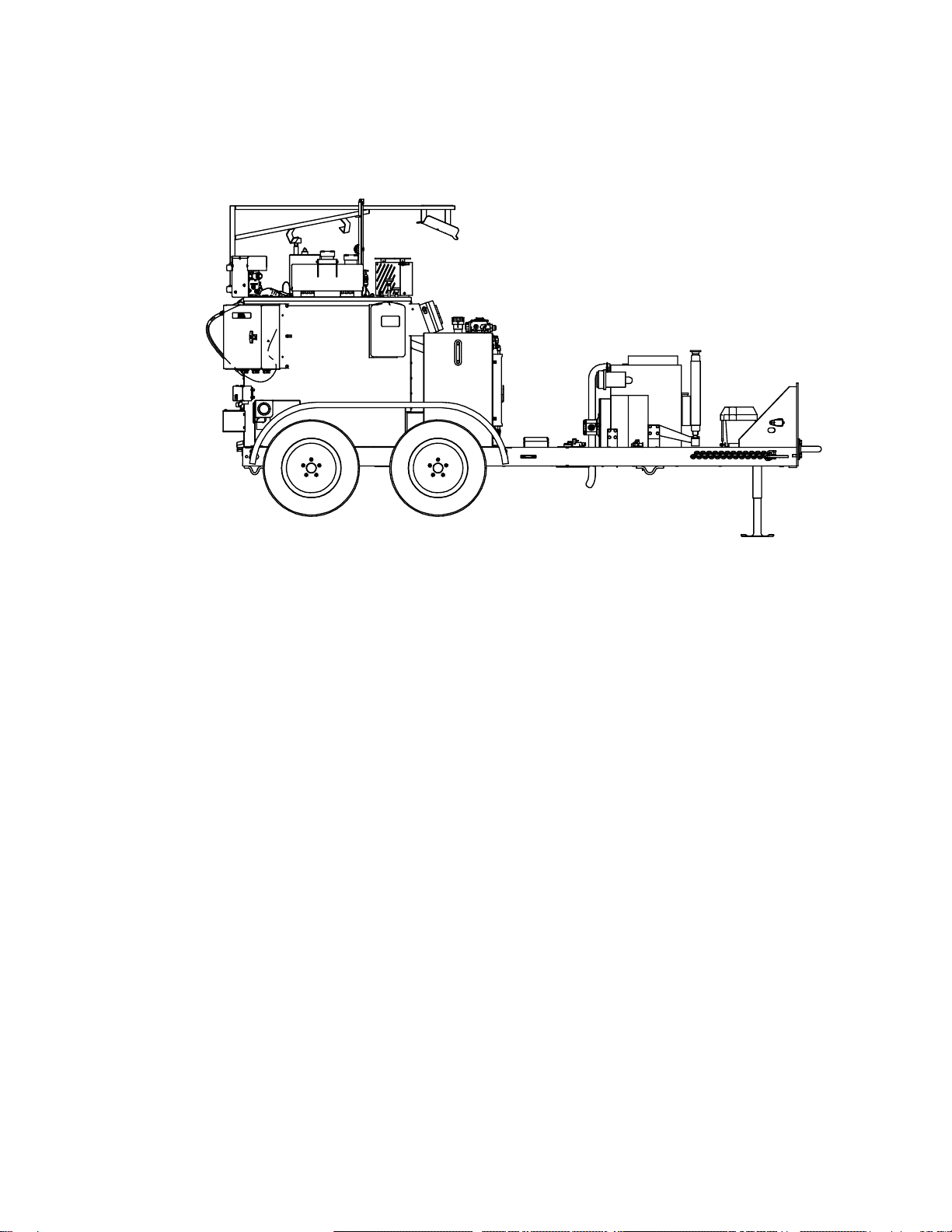
Super Shot 125 Dual Axle Diesel Melter
PN 43600DX

Super Shot 125 Diesel Melter Part
Manual
Table of Contents
1.0 About This Manual.................................................................................................................. 1-1
1.1 How to use this manual....................................................................................................... 1-1
2.0 Safety Precautions.................................................................................................................. 2-1
2.1 General Safety.................................................................................................................... 2-1
2.2 Personal Safety................................................................................................................... 2-1
2.3 Equipment or Operational Safety......................................................................................... 2-1
2.4 California Proposition 65 ..................................................................................................... 2-2
All Crafco, Inc. Equipment........................................................................................... 2-2
All Crafco, Inc. Equipment using a diesel engine......................................................... 2-2
2.5 Towing or Driving for Transporting with Burner On.............................................................. 2-2
2.6 Safety Symbols and Notices................................................................................................ 2-3
3.0 Limited Warranty..................................................................................................................... 3-1
3.1 Warranty Claim Instructions................................................................................................. 3-2
4.0 Machine Specifications ........................................................................................................... 4-1
5.0 Operating Instructions............................................................................................................. 5-1
5.1 Preparing the Machine for Start Up ..................................................................................... 5-1
5.2 Machine Start Up for 43600, 57200, and 43600DX ............................................................. 5-3
5.3 Altitude Compensation System (3CH1 Engine) ................................................................... 5-4
5.4 About the Heated Hose, Wand, Valve, and Tip Guard......................................................... 5-5
5.5 Operating the Electric Hose................................................................................................. 5-6
5.6 Dispensing the Material....................................................................................................... 5-7
5.7 About the Active Screen Pump Protection........................................................................... 5-7
5.8 Loading Material into the Sealant Tank ............................................................................... 5-8
Material Tank Depth Chart........................................................................................... 5-9
5.9 Shutting Down and Cleaning Out the Machine (43600, 57200, and 43600DX).................. 5-10
5.10 Storing the Electric Hose for Transport............................................................................ 5-11
5.11 Overnight Heater Use...................................................................................................... 5-12
5.12 Mounting a Skid Machine................................................................................................ 5-13
5.13 Shot Timer Option........................................................................................................... 5-14
5.14 Storing the Machine ........................................................................................................ 5-14
6.0 Maintenance Instructions........................................................................................................ 6-1
6.1 Engine................................................................................................................................. 6-1
6.2 Hydraulic System ................................................................................................................ 6-1
6.3 Heat Transfer Oil................................................................................................................. 6-1

Super Shot 125 Diesel Melter Part
Manual
Table of Contents
6.4 Wheel Bearing.....................................................................................................................6-1
6.5 Material Sensor Tube ..........................................................................................................6-1
6.6 Cleaning Material Tank and Sensor Area............................................................................6-2
6.7 Lug Nuts..............................................................................................................................6-2
6.8 Brakes................................................................................................................................. 6-2
6.9 Tongue Jack........................................................................................................................6-2
6.10 Temperature Control Calibration........................................................................................6-3
6.11 Cleaning the Melter ...........................................................................................................6-3
6.12 Maintenance Chart ............................................................................................................6-4
6.13 Service Instructions...........................................................................................................6-5
6.14 General Maintenance Parts...............................................................................................6-5
6.15 Recommended Spare Parts...............................................................................................6-6
6.16 Recommended Fluids and Lubricants................................................................................6-7
6.17 Applicable Brands of Heat Transfer Oil..............................................................................6-8
6.18 Typical Heat Transfer Oil Specifications ............................................................................6-8
6.19 Material Pump Replacement..............................................................................................6-9
6.20 Wand Repair Instructions ................................................................................................6-21
Cable Replacement...................................................................................................6-21
Switch Replacement..................................................................................................6-21
Terminal Block Replacement.....................................................................................6-21
Wand Handle Replacement.......................................................................................6-22
6.21 Burner Fuel Filter Replacement.......................................................................................6-25
7.0 How to Use a Multimeter.........................................................................................................7-1
7.1 Checking DC Voltage with a Multimeter...............................................................................7-1
7.2 Checking AC Voltage with Multimeter..................................................................................7-1
7.3 Checking Resistance (Ohms)..............................................................................................7-1
How to Check Wire Continuity .....................................................................................7-1
How to Check RTD Sensor..........................................................................................7-1
7.4 Checking Amperage............................................................................................................7-2
8.0 Troubleshooting (43600, 57200, and 43600DX)......................................................................8-1
8.1 Diesel Burner Troubleshooting ............................................................................................8-1
Symptoms: Burner will Not Ignite.................................................................................8-1
Burner Electrical Troubleshooting................................................................................8-2
Excessive Smoke Coming Out of Exhaust Stack.........................................................8-6
Burner Lights but Shuts Down After 15 Seconds.........................................................8-6

Super Shot 125 Diesel Melter Part
Manual
Table of Contents
Testing DC Controller.................................................................................................. 8-7
Burner Fuel Solenoid Testing...................................................................................... 8-7
Burner Ignition Coil Testing ......................................................................................... 8-8
Bleeding the Burner..................................................................................................... 8-8
Sealant is Heating Slowly.......................................................................................... 8-10
8.2 Mixer Troubleshooting....................................................................................................... 8-11
Symptom: Mixer Does Not Rotate ............................................................................. 8-11
Mixer Electrical Troubleshooting................................................................................ 8-12
Mixer Hydraulic Troubleshooting ............................................................................... 8-16
8.3 Hose Troubleshooting ....................................................................................................... 8-19
Symptom: Hose Does Not Heat................................................................................. 8-19
Hose Electrical Troubleshooting................................................................................ 8-19
Symptom: Trigger is not Working............................................................................... 8-24
RTD Sensor Ohms vs. Temperature ......................................................................... 8-25
8.4 Pump Troubleshooting ...................................................................................................... 8-27
Symptom: Material Does Not Dispense When the Pump is Activated........................ 8-27
Pump Electrical Troubleshooting............................................................................... 8-28
Pump Hydraulic Troubleshooting............................................................................... 8-34
9.0 About the Illustrated Parts List ................................................................................................ 9-1
9.1 Ordering Crafco Parts ......................................................................................................... 9-1
9.2 Super Shot 125 Diesel Melter Assembly 43600................................................................... 9-2
9.3 Super Shot 125 Diesel Melter Skid Mount Assembly 57200................................................ 9-8
9.4 Super Shot 125 Diesel Melter Dual Axle PN 43600DX...................................................... 9-12
9.5 Tank Assembly, All Models ............................................................................................... 9-18
9.6 Control Box Assembly, 43600, 57200, and 43600DX........................................................ 9-20
9.7 Engine Assembly: PN 43600, 57200, and 43600DX.......................................................... 9-22
9.8 Hydraulic Control Valve Assembly: PN 45420 All Models.................................................. 9-24
9.9 Material Flow Control Assembly: PN 46060 All Models ..................................................... 9-26
9.10 Pump/Mixer Motor Assembly: PN 44832 All Models........................................................ 9-28
9.11 Diesel Burner Assembly: PN 46380 All Models ............................................................... 9-30
9.12 Hydraulic Diagram: PN 26554 (43600, and 57200) ......................................................... 9-32
9.13 Hydraulic Diagram: PN 26554DX (43600DX) .................................................................. 9-36
9.14 Diesel Fuel Line Schematic –43600, and 57200 Engines............................................... 9-40
9.15 Diesel Fuel Line Schematic –43600DX Engine............................................................... 9-42
9.16 Electrical Schematic: PN 43600, 57200, and 43600DX................................................... 9-46

Super Shot 125 Diesel Melter Part
Manual
Table of Contents
9.17 Wand Assembly (All Models)...........................................................................................9-48
9.18 Optional Engine Cover for 3CH1 Engine..........................................................................9-50
10.0 Tools and Accessories........................................................................................................10-1

Super Shot 125 Diesel Melter Part
Manual
List of Figures
Fig. 5-1 Hydraulic Fluid Level and Temp. Gauge.......................................................................... 5-2
Fig. 5-2 Heat Transfer Oil Dip Stick............................................................................................... 5-2
Fig. 6-1 Lug bolt Tightening Sequence ......................................................................................... 6-2
Fig. 6-2 Temperature Control Calibration...................................................................................... 6-3
Fig. 6-3 Agitator and Pump Shaft Alignment................................................................................. 6-9
Fig. 6-4 Removal of Motor Mount Assembly ............................................................................... 6-10
Fig. 6-5 Supporting the Agitator Away from the Material Pump................................................... 6-11
Fig. 6-6 Unbolting the Material Pump.......................................................................................... 6-12
Fig. 6-7 Cleaning of the Pump Mounting Plate............................................................................ 6-13
Fig. 6-8 Pump Drive Shaft Dry Fit to Material Pump.................................................................... 6-14
Fig. 6-9 New Material Pump Mounting........................................................................................ 6-15
Fig. 6-10 Agitator Shaft and Paddles Mounting........................................................................... 6-16
Fig. 6-11 Pump Shaft Placement................................................................................................ 6-17
Fig. 6-12 Pump Shaft to Hydraulic Pump Motor Placement ........................................................ 6-18
Fig. 6-13 Agitator Connecting Link.............................................................................................. 6-19
Fig. 6-14 Agitator Chain Tightening Steps................................................................................... 6-20
Fig. 6-15 Switch Wire Location ................................................................................................... 6-22
Fig.6-16 Wire Routing................................................................................................................. 6-22
Fig.6-17 Terminal Block Wiring................................................................................................... 6-23
Fig.6-18 Actuator Spring Location............................................................................................... 6-23
Fig.6-19 Actuator / Trigger Assembly.......................................................................................... 6-24
Fig. 7-1 Standard Multimeter......................................................................................................... 7-2
Fig. 7-2 Clamp –On Amp Meter/Multimeter.................................................................................. 7-3
Fig. 8-1 Diesel Burner Schematic ................................................................................................. 8-5
Fig. 8-2 Diesel Burner Electrode Adjustment ................................................................................ 8-9
Fig. 8-3 Diesel Burner Air Settings................................................................................................ 8-9
Fig. 8-4 Checking Din Plug Voltage ............................................................................................ 8-14
Fig. 8-5 Mixer Schematic............................................................................................................ 8-15
Fig. 8-6 Hydraulic Valve Pressure Setting................................................................................... 8-17
Fig. 8-7 Din Plug Layout ............................................................................................................. 8-18
Fig. 8-8 Junction Box Voltage Testing......................................................................................... 8-21

Super Shot 125 Diesel Melter Part
Manual
List of Figures
Fig. 8-9 Hose Circuit Schematic..................................................................................................8-22
Fig. 8-10 Junction Box Wiring .....................................................................................................8-23
Fig. 8-11 Pump Schematic..........................................................................................................8-33
Fig. 9-1 Super Shot 125 Diesel Melter: PN 43600.........................................................................9-2
Fig. 9-2 Super Shot 125 Diesel Melter: PN 43600 (continued)......................................................9-4
Fig. 9-3 Super Shot 125 Diesel Melter: PN 43600 (continued)......................................................9-6
Fig. 9-4 Super Shot 125 Diesel Melter Skid Mount Assembly 57200.............................................9-8
Fig. 9-5 Super Shot 125 Diesel Melter Skid Mount Assembly 57200 (continued)........................9-10
Fig. 9-6 Super Shot 125 Diesel Melter Dual Axle PN 43600DX...................................................9-12
Fig. 9-7 Super Shot 125 Diesel Melter Dual Axle PN 43600DX (continued)................................9-14
Fig. 9-8 Super Shot 125 Diesel Melter Dual Axle PN 43600DX (continued)................................9-16
Fig. 9-9 Tank Assembly: All Models............................................................................................9-18
Fig. 9-10 Control Box Assembly, 43600, 57200, and 43600DX...................................................9-20
Fig. 9-11 Engine Assembly: PN 43600, 57200, and 43600DX ....................................................9-22
Fig. 9-12 Hydraulic Control Valve Assembly: PN 45420 All Models.............................................9-24
Fig. 9-13 Material Flow Control Assembly: PN 46060 All Models................................................9-26
Fig. 9-14 Pump/Mixer Motor Assembly: PN 44832 All Models.....................................................9-28
Fig. 9-15 Diesel Burner Assembly: PN 46380 All Models............................................................9-30
Fig. 9-16 Hydraulic Diagram: PN 26554 (43600, and 57200)......................................................9-32
Fig. 9-17 Hydraulic Diagram: PN 26554 (43600, and 57200) (continued)....................................9-34
Fig. 9-18 Hydraulic Diagram: PN 26554DX (43600DX)...............................................................9-36
Fig. 9-19 Hydraulic Diagram: PN 26554DX (43600DX continued)...............................................9-38
Fig. 9-20 Diesel Fuel Line Schematic –43600, and 57200 Engines............................................9-40
Fig. 9-21 Diesel Fuel Line Schematic –43600DX Engine...........................................................9-42
Fig. 9-22 Diesel Fuel Line Schematic –43600DX Engine (continued).........................................9-44
Fig. 9-23 Electrical Schematic: PN 43600, 57200, and 43600DX................................................9-46
Fig. 9-24 Wand Assembly (All Models) .......................................................................................9-48
Fig. 9-25 Optional Engine Cover for 3CH1 Engine......................................................................9-50

Super Shot 125 Diesel Melter Part
Manual
List of Tables
Table 2-1 Safety Symbols and Notices......................................................................................... 2-3
Table 2-2 Safety Symbols and Notices (continued)....................................................................... 2-4
Table 4-1 Machine Specifications................................................................................................. 4-1
Table 5-1 Preparing the Machine for Start Up............................................................................... 5-1
Table 5-2 Starting the Burner........................................................................................................ 5-3
Table 5-3 Starting the Burner for Electric Hose (continued).......................................................... 5-4
Table 5-4 Operating the Electric Hose.......................................................................................... 5-6
Table 5-5 Dispensing the Material ................................................................................................ 5-7
Table 5-6 Loading Material into the Sealant Tank......................................................................... 5-8
Table 5-7 Material Tank Depth Chart............................................................................................ 5-9
Table 5-8 Shutting Down and Cleaning Out the Machine (43600, 57200, and 43600DX) ........... 5-10
Table 5-9 Hose for Transport Instructions................................................................................... 5-11
Table 5-10 Overnight Heater Use ............................................................................................... 5-12
Table 5-11 Mounting a Skid Machine.......................................................................................... 5-13
Table 6-1 Maintenance Chart........................................................................................................ 6-4
Table 6-2 Service Instructions....................................................................................................... 6-5
Table 6-3 General Maintenance Parts .......................................................................................... 6-5
Table 6-4 General Maintenance Parts (continued)........................................................................ 6-6
Table 6-5 Recommended Spare Parts.......................................................................................... 6-6
Table 6-6 Recommended Fluids and Lubricants........................................................................... 6-7
Table 6-7 Applicable Brand of Heat Transfer Oil........................................................................... 6-8
Table 6-8 Material Pump Replacement......................................................................................... 6-9
Table 6-9 Material Pump Replacement (continued).................................................................... 6-10
Table 6-10 Material Pump Replacement (continued).................................................................. 6-11
Table 6-11 Material Pump Replacement (continued).................................................................. 6-12
Table 6-12 Material Pump Replacement (continued).................................................................. 6-13
Table 6-13 Material Pump Replacement (continued).................................................................. 6-14
Table 6-14 Material Pump Replacement (continued).................................................................. 6-15
Table 6-15 Material Pump Replacement (continued).................................................................. 6-16
Table 6-16 Material Pump Replacement (continued).................................................................. 6-17
Table 6-17 Material Pump Replacement (continued).................................................................. 6-18

Super Shot 125 Diesel Melter Part
Manual
List of Tables
Table 6-18 Material Pump Replacement (continued) ..................................................................6-19
Table 6-19 Material Pump Replacement (continued) ..................................................................6-20
Table 6-20 Burner Fuel Filter Replacement.................................................................................6-25
Table 8-1 Basic Visual Troubleshooting........................................................................................8-1
Table 8-2 Basic Visual Troubleshooting (continued) .....................................................................8-2
Table 8-3 Burner Electrical Troubleshooting .................................................................................8-2
Table 8-4 Burner Electrical Troubleshooting (continued)...............................................................8-3
Table 8-5 Burner Electrical Troubleshooting (continued)...............................................................8-4
Table 8-6 Smoke Coming Out of Exhaust Stack ...........................................................................8-6
Table 8-7 Burner Lights but Shuts Down After 15 Seconds...........................................................8-6
Table 8-8 Testing the DC Controller..............................................................................................8-7
Table 8-9 Burner Fuel Solenoid Test.............................................................................................8-7
Table 8-10 Burner Ignition Coil Test..............................................................................................8-8
Table 8-11 Bleeding the Diesel Burner..........................................................................................8-8
Table 8-12 Sealant is Heating Slowly..........................................................................................8-10
Table 8-13 Basic Visual Troubleshooting....................................................................................8-11
Table 8-14 Mixer Electrical Troubleshooting ...............................................................................8-12
Table 8-15 Mixer Electrical Troubleshooting (continued).............................................................8-13
Table 8-16 Mixer Hydraulic Troubleshooting...............................................................................8-16
Table 8-17 Basic Visual Hose Troubleshooting...........................................................................8-19
Table 8-18 Hose Electrical Troubleshooting................................................................................8-19
Table 8-19 Hose Electrical Troubleshooting (continued).............................................................8-20
Table 8-20 Trigger is Not Working...............................................................................................8-24
Table 8-21 RTD Sensor Ohms vs. Temperature.........................................................................8-25
Table 8-22 RTD Sensor Ohms vs. Temperature (continued).......................................................8-26
Table 8-23 Basic Visual Pump Troubleshooting..........................................................................8-27
Table 8-24 Pump Electrical Troubleshooting...............................................................................8-28
Table 8-25 Pump Electrical Troubleshooting (continued)............................................................8-29
Table 8-26 Pump Electrical Troubleshooting (continued)............................................................8-30
Table 8-27 Pump Electrical Troubleshooting (continued)............................................................8-31
Table 8-28 Pump Electrical Troubleshooting (continued)............................................................8-32

Super Shot 125 Diesel Melter Part
Manual
List of Tables
Table 8-29 Pump Electrical Troubleshooting (continued)............................................................ 8-33
Table 8-30 Pump Hydraulic Troubleshooting.............................................................................. 8-34
Table 9-1 Super Shot 125 Diesel Melter: PN 43600...................................................................... 9-3
Table 9-2 Super Shot 125 Diesel Melter: PN 43600 (continued)................................................... 9-5
Table 9-3 Super Shot 125 Diesel Melter: PN 43600 (continued)................................................... 9-7
Table 9-4 Super Shot 125 Diesel Melter Skid Mount Assembly 57200.......................................... 9-9
Table 9-5 Super Shot 125 Diesel Melter Skid Mount Assembly 57200 (continued)..................... 9-11
Table 9-6 Super Shot 125 Diesel Melter Dual Axle PN 43600DX................................................ 9-13
Table 9-7 Super Shot 125 Diesel Melter Dual Axle PN 43600DX (continued)............................. 9-15
Table 9-8 Super Shot 125 Diesel Melter Dual Axle PN 43600DX (continued)............................. 9-17
Table 9-9 Tank Assembly: All Models......................................................................................... 9-19
Table 9-10 Control Box Assembly, 43600, 57200, and 43600DX................................................ 9-21
Table 9-11 Engine Assembly: PN 43600, 57200, and 43600DX................................................. 9-23
Table 9-12 Hydraulic Control Valve Assembly: PN 45420 All Models ......................................... 9-25
Table 9-13 Material Flow Control Assembly: PN 46060 All Models............................................. 9-27
Table 9-14 Pump/Mixer Motor Assembly: PN 44832 All Models ................................................. 9-29
Table 9-15 Diesel Burner Assembly: PN 46380 All Models......................................................... 9-31
Table 9-16 Hydraulic Diagram: PN 26554 (43600, and 57200)................................................... 9-33
Table 9-17 Hydraulic Diagram: PN 26554 (43600, and 57200 continued)................................... 9-35
Table 9-18 Hydraulic Diagram: PN 26554DX (43600DX)............................................................ 9-37
Table 9-19 Hydraulic Diagram: PN 26554DX (43600DX continued)............................................ 9-39
Table 9-20 Diesel Fuel Line Schematic –43600, and 57200 Engines......................................... 9-41
Table 9-21 Diesel Fuel Line Schematic –43600DX Engine........................................................ 9-43
Table 9-22 Diesel Fuel Line Schematic –43600DX Engine (continued) ..................................... 9-45
Table 9-23 Electrical Schematic: PN 43600, 57200, and 43600DX............................................. 9-47
Table 9-24 Wand Assembly (All Models) .................................................................................... 9-49
Table 9-25 Optional Engine Cover for 3CH1 Engine................................................................... 9-51

Super Shot 125 Diesel Melter Part
Manual
Chapter 1 Introduction
©2019 by Crafco, Inc. All Rights Reserved Introduction 1-1
1.0 About This Manual
This manual is supplied with each new Crafco Super Shot 125 Diesel Melter. The manual assists
your machine operators in the proper use of the melter applicator and provides information about
the machine’s mechanical functions.
Your Crafco Super Shot 125 Diesel Melter is specially made to give excellent service and save
maintenance expense. However, as with all specially engineered equipment, you get best results at
minimum cost if you:
Operate your machine as instructed in this manual.
Maintain your machine regularly as stated in this manual.
1.1 How to use this manual
This manual is formatted to start each new chapter on the right page. There may be a blank page
on the left page if the previous chapter ends on the right page.
If you are viewing this in a digital format (PDF) the following features are available:
1. The Table of Contents, List of Tables, and List of Figures are all hyperlinks; when mouse is left-
clicked on section, table, or figure you will be sent to that page.
2. The blue highlighted text throughout the manual is a hyperlink; when mouse is left-clicked you
will be sent to that page, table, or figure.
3. The panel to the left in the PDF is a bookmarks panel, if you left-click on any section/heading in
the bookmarks panel you will be sent to that page.


Super Shot 125 Diesel Melter Part
Manual
Chapter 2 Safety
©2019 by Crafco, Inc. All Rights Reserved………………………………………..…………………………………Safety 2-1
2.0 Safety Precautions
For more in-depth safety information, please see Safety Manual (PN 26221), which comes with the
machine. Or contact your nearest authorized Crafco Distributor at crafco.com/Distributors.
2.1 General Safety
•Crafco, Inc. assumes no liability for an accident or injury incurred through improper use of
the machine.
•Read this manual thoroughly before operating the machine.
•Obey all CAUTION and WARNING signs posted on the machine.
•Make sure an operator fully knows how to operate the machine before using the machine.
2.2 Personal Safety
•The high operating temperatures of this machine and the sealant it contains requires that
protective clothing, gloves, hard-soled shoes, and safety glasses or a face shield be worn at
all times by operators of the machine.
•Prevent water from going into any part of the machine. If there is indication of water in the
heat transfer oil system, warm heating oil to 250-300°F for 2 to 3 hours.
•Bodily contact with hot sealant or heat transfer oil can cause severe burns.
•If the mixer is not stopped before adding solid material, hot material can get on an operator’s
body and cause severe burns.
•Keep hands, feet, and clothing away from all moving parts.
2.3 Equipment or Operational Safety
•Do not operate the machine in buildings or work areas that do not have sufficient airflow.
•Shut-down the burner and the engine before refilling the fuel tank.
•Make sure the mixer stops before adding solid material to the sealant tank. Lift the lid, place
the material on the lid, and close the lid. The mixer should restart automatically.
•Always keep a correctly maintained fire extinguisher near the machine and know how to use
it.
•DO NOT heat transfer oil to a temperature of more than 525°F.
•DO NOT put too much heat transfer oil in the reservoir. The expansion of oil while it heats
up can cause overflow. Check the oil each day before starting the burner. With the machine
on a level surface, check the heat transfer oil level using the mark on the dipstick closest to
the current oil temperature (0°F, 70°F, or 150°F) See Fig. 5-2 Heat Transfer Oil Dip Stick.
Add oil if required. Use only recommended heat transfer oil. Change the oil after 500 hours
of machine operation, or one year, whichever comes first.
•Follow the operating instructions for starting and shutting down the burner. Instructions are
mounted on the control box on the machine.
•Calibrate the temperature control operation after each 50 hours of machine operation. Refer
to section 6.10 Temperature Control Calibration.
•Replace any hoses that show signs of wear, fraying, or splitting.
•Make sure all fittings and joints are tight and do not leak each time the machine is used.
•Do not leave the machine unattended while the burner is lit.
•Tighten all bolts and screws every 100 hours of machine operation.

Super Shot 125 Diesel Melter Part
Manual
Chapter 2 Safety
©2019 by Crafco, Inc. All Rights Reserved………………………………………..…………………………………Safety 2-2
2.4 California Proposition 65
The state of California currently maintains a list of chemicals that can cause cancer, birth defects, or
other reproductive harm. Your Crafco, Inc. equipment comes with the following warnings:
All Crafco, Inc. Equipment
All Crafco, Inc. Equipment using a diesel engine
2.5 Towing or Driving for Transporting with Burner On
The burner in your Crafco machine is designed for operation only while the unit is parked or towed
at slow speeds while applying sealant at a jobsite. When driving or towing this machine for
transport, the burner shall be turned off. Operating the burner when transporting the machine is a
violation of The Code of Federal Regulations, CFR Title 49, Part 392, Subpart G, 392.67 and may
cause damage to the burner and/or machine.
CAUTION
The burner in your Crafco machine is designed for operation only while the unit is parked or
towed at slow speeds while applying sealant at a jobsite. When driving or towing this
machine for transport, the burner shall be turned off.
! WARNING: Cancer and Reproductive Harm - www.P65Warnings.ca.gov
26471N
! WARNING: Breathing diesel engine exhaust exposes you to chemicals
known to the State of California to cause cancer and birth defects or other
reproductive harm.
• Always start and operate the engine in a well-ventilated area.
• If in an enclosed area, vent the exhaust to the outside.
• Do not modify or tamper with the exhaust system.
• Do not idle the engine except as necessary.
For more information go to www.P65warnings.ca.gov/diesel. 26307

Super Shot 125 Diesel Melter Part
Manual
Chapter 2 Safety
©2019 by Crafco, Inc. All Rights Reserved………………………………………..…………………………………Safety 2-3
2.6 Safety Symbols and Notices
Important safety symbols and notices are marked on the machine and in this manual. Failure to
comply could result in equipment damage, operational malfunction, serious injury, or death. Please
read and comply with all symbols and notices. The table below includes the most commonly used
symbols and notices.
Symbol
Item
Remarks
WARNING
Warning
Refers to possible bodily injury or death.
CAUTION
Caution
Refers to possible equipment damage or operational
malfunction.
Severe Burn Hazard
Hot material can cause severe burns.
Protective Shoes
Wear hard-soled work shoes.
Protective Gloves
Wear heat-resistant gloves.
Protective Face or Eye Wear
Wear face shield or safety glasses.
Body Crush Hazard
Do not stand between trailer and hitch when hooking
melter to truck.
Table 2-1 Safety Symbols and Notices

Super Shot 125 Diesel Melter Part
Manual
Chapter 2 Safety
©2019 by Crafco, Inc. All Rights Reserved………………………………………..…………………………………Safety 2-4
Symbol
Item
Remark
Crush Hazard
Keep feet and legs clear.
Pinch Hazard
Keep hands and feet clear.
Exhaust Hazard
Avoid breathing engine exhaust.
Read Manual
Read and understand operator and safety manuals
before operating machine.
Table 2-2 Safety Symbols and Notices (continued)
Other manuals for Crafco SUPER SHOT 125
1
Table of contents
Other Ergon Construction Equipment manuals
Popular Construction Equipment manuals by other brands

OBO Bettermann
OBO Bettermann 1814 FT Mounting instructions

JB Pipepuller
JB Pipepuller 1700 Operator's manual

Altrad
Altrad BELLE PCEL 320X Operator's manual

MULTIQUIP
MULTIQUIP Mikasa MT77HFR Operation manual

cascade corporation
cascade corporation QFM Nstallation instructions

Case
Case NCDC11500 Service manual