Ergon Crafco Patcher 4 Programming manual

For January 2023 & Newer Patcher 4’s
Operator/Parts Manual –56645N
Revision O

Fill in the appropriate fields that apply to this machine.
Machine S/N: ___________________________________
Engine S/N: ____________________________________
Gear Box S/N: __________________________________

Patcher 4 Operator/Part
Manual
Revisions
Revision
Description
Date

Patcher 4 Operator/Part
Manual
Machine Views

Patcher 4 Operator/Part
Manual
Machine Views

Patcher 4 Operator/Part
Manual
Table of Contents
Contents
1.0 About This Manual................................................................................................................ 1-1
How to use this Manual ................................................................................................... 1-1
2.0 Safety Precautions ............................................................................................................... 2-1
General Safety................................................................................................................. 2-1
Personal Safety............................................................................................................... 2-1
Equipment or Operational Safety..................................................................................... 2-1
California Proposition 65.................................................................................................. 2-2
All Crafco, Inc. Equipment ....................................................................................... 2-2
All Crafco, Inc. Equipment using a Diesel Engine.................................................... 2-2
Towing or Driving for Transporting with Burner On .......................................................... 2-2
Safety Symbols and Notices............................................................................................ 2-3
3.0 Limited Warranty .................................................................................................................. 3-1
Warranty Claim Instructions............................................................................................. 3-2
4.0 Machine Specifications......................................................................................................... 4-1
5.0 Operating Instructions........................................................................................................... 5-1
Introduction...................................................................................................................... 5-1
Preparing the Machine for Start Up.................................................................................. 5-1
Starting the Engine and Burner........................................................................................ 5-5
Altitude Compensation System........................................................................................ 5-7
Loading Material into Material Tank................................................................................. 5-7
Dispensing the Material................................................................................................... 5-9
Shutting Down and Cleaning Out the Machine............................................................... 5-10
Storing the Machine....................................................................................................... 5-11
Overnight Heaters ......................................................................................................... 5-11
Hot Applied Patching Material Placement.................................................................... 5-12
Application Steps................................................................................................... 5-13
Heated Toolbox Operation........................................................................................... 5-15
Material Tank Depth to Capacity Chart........................................................................ 5-17
Removing Optional Heated Chute ............................................................................... 5-18
Mounting a Skid Machine............................................................................................. 5-21
6.0 Maintenance Instructions...................................................................................................... 6-1
Engine............................................................................................................................. 6-1
Hydraulic System............................................................................................................. 6-1

Patcher 4 Operator/Part
Manual
Table of Contents
Heat Transfer Oil .............................................................................................................6-1
Mixer Packing Gland Seals..............................................................................................6-1
Mixer Shaft Bearings........................................................................................................6-1
Material Sensor Tube.......................................................................................................6-1
Lug Nuts..........................................................................................................................6-1
Wheel Bearing.................................................................................................................6-2
Brakes .............................................................................................................................6-2
Tongue Jack..................................................................................................................6-2
Water Separator.............................................................................................................6-2
Temperature Control Calibration....................................................................................6-2
Maintenance Chart.........................................................................................................6-3
Service Instructions........................................................................................................6-4
Recommended Fluids and Lubricants............................................................................6-4
General Maintenance Parts ...........................................................................................6-5
Recommended Spare Parts...........................................................................................6-5
Applicable Brands of Heat Transfer Oil..........................................................................6-6
Typical Heat Transfer Oil Specifications.........................................................................6-6
Changing the Heat Transfer Oil......................................................................................6-7
Adjusting the Discharge Gate ........................................................................................6-8
Adjusting and Replacing Mixer Shaft Packing................................................................6-9
Cleaning Material Tank and Sensor Area.....................................................................6-10
Cleaning the Melter......................................................................................................6-10
Burner Fuel Filter Replacement ...................................................................................6-10
7.0 How to Use a Multimeter.......................................................................................................7-1
Checking DC Voltage with a Multimeter...........................................................................7-1
Checking Resistance (Ohms) ..........................................................................................7-1
How to Check Wire Continuity .................................................................................7-1
How to Check RTD Sensor......................................................................................7-1
Checking Amperage ........................................................................................................7-2
8.0 Troubleshooting....................................................................................................................8-1
Burner Troubleshooting ...................................................................................................8-1
Symptom: Burner will Not Ignite...............................................................................8-1
Burner Lights but Shuts Down After 15 Seconds .............................................................8-6
Electrical Schematic.........................................................................................................8-7

Patcher 4 Operator/Part
Manual
Table of Contents
Testing the DC Controller ................................................................................................ 8-8
Fuel Solenoid Troubleshooting........................................................................................ 8-8
Ignition Coil Troubleshooting ........................................................................................... 8-9
Bleeding the Diesel Burners ............................................................................................ 8-9
Smoke Coming Out of the Exhaust Stack...................................................................... 8-10
Burner Electrode Adjustment......................................................................................... 8-11
Burner Air Settings....................................................................................................... 8-11
Material is Heating Slowly............................................................................................ 8-12
Mixer Troubleshooting................................................................................................. 8-12
Symptom: Mixer Does Not Rotate.......................................................................... 8-12
Mixer Hydraulic Troubleshooting.................................................................................. 8-16
Hydraulic Schematic.................................................................................................... 8-18
RTD Sensor Ohms vs. Temperature............................................................................ 8-19
9.0 About the Illustrated Parts List.............................................................................................. 9-1
Ordering Crafco Parts...................................................................................................... 9-1
Patcher 4 Parts List ......................................................................................................... 9-2
Fuel and Hydraulic Tanks Parts List ................................................................................ 9-8
Engine Parts List ........................................................................................................... 9-10
Hydraulic Schematic and Parts List ............................................................................... 9-12
Hydraulic Valve Parts List.............................................................................................. 9-16
Hitch Parts List .............................................................................................................. 9-17
Diesel Fuel Line Schematic ........................................................................................... 9-18
Main Diesel Burner Parts List (P/N 46380) .................................................................... 9-20
Toolbox Diesel Burner Parts List (P/N 57485N)........................................................... 9-21
Control Box Parts List (P/N 47265N)............................................................................ 9-22
Electrical Wiring Harness Parts List............................................................................. 9-24
Electrical Schematic Parts List..................................................................................... 9-26
Heated Toolbox Parts List (P/N 57450N)..................................................................... 9-28
Optional Material Chute Parts List (P/N 56895N)......................................................... 9-30
Optional Heated Chute Parts List (P/N 56890N).......................................................... 9-32
Hydraulic Schematic for Optional Heated Chute.......................................................... 9-36
Heated Chute Pump and Motor Assembly (P/N 41696)............................................... 9-40
Patcher II Options........................................................................................................ 9-42
10.0 Tools and Accessories...................................................................................................... 10-1

Patcher 4 Operator/Part
Manual
Table of Contents

Patcher 4 Operator/Part
Manual
List of Figures
Figure 5-1 Hydraulic and Diesel Fill Caps................................................................................... 5-2
Figure 5-2 Hydraulic Fluid Level and Temp Gauge..................................................................... 5-2
Figure 5-3 Heat Transfer Oil Dipstick.......................................................................................... 5-3
Figure 5-4 Discharge Gate ......................................................................................................... 5-4
Figure 5-5 Mixer & Engine Speed Switch ................................................................................... 5-4
Figure 5-6 Mixer Bearings .......................................................................................................... 5-5
Figure 5-7 Control Panel ............................................................................................................ 5-6
Figure 5-8 Loading Material Using the Lid.................................................................................. 5-8
Figure 5-9 Lid Hold-Down/Lid Pins............................................................................................. 5-8
Figure 5-10 Flow Control Knob................................................................................................... 5-9
Figure 5-11 Heated Toolbox..................................................................................................... 5-16
Figure 5-12 Material Tank Depth to Capacity Chart.................................................................. 5-17
Figure 5-13 Optional Heated Chute Components (P/N 56890N)............................................... 5-20
Figure 6-1 Lug Bolt Tightening Sequence................................................................................... 6-1
Figure 6-2 Temperature Control Calibration ............................................................................... 6-2
Figure 6-3 Heat Transfer Oil Drain Plug and Fill Ports................................................................ 6-7
Figure 7-1 Standard Multimeter.................................................................................................. 7-2
Figure 7-2 Clamp-On Amp Meter/Multimeter.............................................................................. 7-3
Figure 8-1 Electrical Schematic (PN 26582P4)........................................................................... 8-7
Figure 8-2 Diesel Burner Electrode Adjustment........................................................................ 8-11
Figure 8-3 Diesel Burner Air Settings ....................................................................................... 8-11
Figure 8-4 Checking Din Plug Voltage...................................................................................... 8-15
Figure 8-5 Hydraulic Pressure Adjustment Location................................................................. 8-17
Figure 8-6 Din Plug Layout....................................................................................................... 8-17
Figure 8-7 Hydraulic Schematic (P/N 56690N)......................................................................... 8-18
Figure 9-1 Right ISO View.......................................................................................................... 9-2
Figure 9-2 Left ISO View............................................................................................................ 9-4
Figure 9-3 Top Section View ...................................................................................................... 9-6
Figure 9-4 Fuel and Hydraulic Tanks Section View..................................................................... 9-8
Figure 9-5 Engine..................................................................................................................... 9-10
Figure 9-6 Hydraulic Schematic (P/N 56690N)......................................................................... 9-12
Figure 9-7 Hydraulic Schematic (PN 56690N) (continued)........................................................ 9-14
Figure 9-8 Hydraulic Valve ....................................................................................................... 9-16
Figure 9-9 Hitch........................................................................................................................ 9-17
Figure 9-10 Diesel Fuel Line Schematic (P/N 26599)............................................................... 9-18
Figure 9-11 Main Diesel Burner (P/N 46380)............................................................................ 9-20
Figure 9-12 Toolbox Diesel Burner (P/N 57485N) .................................................................... 9-21
Figure 9-13 Control Box Parts List (P/N 47265N)..................................................................... 9-22
Figure 9-14 Electrical Wiring Harness Parts List....................................................................... 9-24

Patcher 4 Operator/Part
Manual
List of Figures
Figure 9-15 Electrical schematic parts list (P/N 26582P4).........................................................9-26
Figure 9-16 Heated Toolbox Parts List (P/N 57450N)...............................................................9-28
Figure 9-17 Optional Material Chute (P/N 56895N)...................................................................9-30
Figure 9-18 Optional Heated Chute (P/N 56890N)....................................................................9-32
Figure 9-19 Optional Heated Chute Parts List (continued)........................................................9-34
Figure 9-20 Hydraulic Schematic for Optional Heated Chute....................................................9-36
Figure 9-21 Hydraulic Schematic for Optional Heated Chute (continued) .................................9-38
Figure 9-22 Heated Chute Pump and Motor Assembly (P/N 41696).........................................9-40
Figure 9-23 Patcher 4 Options..................................................................................................9-42
Figure 9-24 Patcher 4 Options..................................................................................................9-44

Patcher 4 Operator/Part
Manual
List of Tables
Table 2-1 Safety Symbols and Notices....................................................................................... 2-3
Table 2-2 Safety Symbols and Notices (continued).................................................................... 2-4
Table 4-1 Machine Specifications............................................................................................... 4-1
Table 5-1 Preparing the Machine for Start Up............................................................................. 5-1
Table 5-2 Starting the Engine and Burner................................................................................... 5-5
Table 5-3 Loading Material into the Material Tank...................................................................... 5-7
Table 5-4 Dispensing the Material.............................................................................................. 5-9
Table 5-5 Shutting Down and Cleaning Out the Machine ......................................................... 5-10
Table 5-6 Overnight Heaters .................................................................................................... 5-11
Table 5-7 Overnight Heaters (continued).................................................................................. 5-12
Table 5-8 Application Steps...................................................................................................... 5-13
Table 5-9 Application Steps (continued)................................................................................... 5-14
Table 5-10 Heated Toolbox Operation...................................................................................... 5-15
Table 5-11 Heated Toolbox Operation (continued)................................................................... 5-16
Table 5-12 Temporary Removal of Optional Heated Chute ...................................................... 5-18
Table 5-13 Complete Removal of Optional Heated Chute........................................................ 5-19
Table 5-14 Mounting a Skid Machine ....................................................................................... 5-21
Table 6-1 Maintenance Chart..................................................................................................... 6-3
Table 6-2 Maintenance Chart (continued)................................................................................... 6-4
Table 6-3 Service Instructions.................................................................................................... 6-4
Table 6-4 Recommended Fluids and Lubricants......................................................................... 6-4
Table 6-5 General Maintenance Parts........................................................................................ 6-5
Table 6-6 Recommended Spare Parts........................................................................................ 6-5
Table 6-7 Applicable Brand of Heat Transfer Oil......................................................................... 6-6
Table 6-8 Typical Heat Transfer Oil Specifications..................................................................... 6-6
Table 6-9 Changing the Heat Transfer Oil.................................................................................. 6-7
Table 6-10 Adjusting the Discharge Gate................................................................................... 6-8
Table 6-11 Adjusting and Replacing Mixer Shaft Packing........................................................... 6-9
Table 6-12 Burner Fuel Filter Replacement.............................................................................. 6-10
Table 8-1 Burner Basic Visual Troubleshooting.......................................................................... 8-1
Table 8-2 Burner Electrical Troubleshooting Part 1..................................................................... 8-2
Table 8-3 Burner Lights but Shuts Down After 15 Seconds........................................................ 8-6
Table 8-4 Testing the DC Controller........................................................................................... 8-8
Table 8-5 Fuel Solenoid Troubleshooting................................................................................... 8-8
Table 8-6 Ignition Coil Troubleshooting ...................................................................................... 8-9
Table 8-7 Bleeding the Diesel Burners ....................................................................................... 8-9
Table 8-8 Smoke Coming Out of the Exhaust Stack................................................................. 8-10
Table 8-9 Burner Air Settings ................................................................................................... 8-11
Table 8-10 Material is Heating Slowly....................................................................................... 8-12

Patcher 4 Operator/Part
Manual
List of Tables
Table 8-11 Mixer Basic Visual Troubleshooting........................................................................8-12
Table 8-12 Mixer Basic Visual Troubleshooting (continued)......................................................8-13
Table 8-13 Mixer Electrical Troubleshooting.............................................................................8-13
Table 8-14 Mixer Electrical Troubleshooting (continued)...........................................................8-14
Table 8-15 Mixer Electrical Troubleshooting (continued)...........................................................8-15
Table 8-16 Mixer Hydraulic Troubleshooting.............................................................................8-16
Table 8-17 RTD Sensor Ohms vs. Temperature.......................................................................8-19
Table 9-1 Right Iso View Parts List.............................................................................................9-3
Table 9-2 Left View Parts List.....................................................................................................9-5
Table 9-3 Top Section View Parts List........................................................................................9-7
Table 9-4 Fuel and Hydraulic Tanks Parts List............................................................................9-8
Table 9-5 Engine Parts List.......................................................................................................9-11
Table 9-6 Hydraulic Parts List...................................................................................................9-13
Table 9-7 Hydraulic Parts List (continued) ................................................................................9-15
Table 9-8 Hydraulic Valve Parts List.........................................................................................9-16
Table 9-9 Hitch Parts List..........................................................................................................9-17
Table 9-10 Diesel Fuel Line Schematic Parts List.....................................................................9-19
Table 9-11 Main Diesel Burner Parts List (P/N 46380)..............................................................9-21
Table 9-12 Toolbox Diesel Burner (P/N 57485N)......................................................................9-21
Table 9-13 Control Box Parts List (P/N 47265N).......................................................................9-23
Table 9-14 Electrical Wiring Harness Parts List........................................................................9-24
Table 9-15 Electrical Schematic Parts List................................................................................9-27
Table 9-16 Heated Toolbox Parts List (P/N 57450N)................................................................9-29
Table 9-17 Optional Material Chute (56895N)...........................................................................9-31
Table 9-18 Optional Heated Chute Parts List............................................................................9-33
Table 9-19 Optional Heated Chute Parts List (continued).........................................................9-35
Table 9-20 Hydraulic Schematic for Optional Heated Chute Parts List......................................9-37
Table 9-21 Hydraulic Schematic for Optional Heated Chute Parts List (continued)...................9-39
Table 9-22 Heated Chute Pump and Motor Assembly Parts List...............................................9-41
Table 9-23 Options Parts List ...................................................................................................9-43
Table 9-24 Options Parts List (continued).................................................................................9-45


Patcher 4 Operator/Part
Manual
Chapter 1 Introduction
©2023 by Crafco, Inc. All Rights Reserved…………………………………………………………………Introduction 1-1
1.0 About This Manual
This manual is supplied with each new Crafco Patcher 4. The manual assists your machine
operators in the proper use of the Patcher 4 and provides information about the machine’s
mechanical functions.
Your Crafco Patcher 4 is specially made to give excellent service and save maintenance expense.
However, as with all specially engineered equipment, you will get the best results at minimum cost if
you:
•Operate your machine as instructed in this manual.
•Maintain your machine regularly as stated in this manual.
How to use this Manual
This manual is formatted to start each new chapter on the right page. There may be a blank page
on the left page if the previous chapter ends on the right page.
If you are viewing this in a digital format (PDF) the following features are available:
1. The Table of Contents, List of Tables, and List of Figures are all hyperlinks, when left
mouse clicked on section, table, or figure you will be sent to that page.
2. The blue highlighted text throughout the manual is a hyperlink, when left mouse clicked you
will be sent to that page, table, or figure.
3. The panel to the left in the PDF is a bookmarks panel, if you left mouse click on any
section/heading in the bookmarks panel you will be sent to that page.
4. There is an attachments icon (paper clip) to the left of the bookmarks, this is where you will
find full size prints of the control box, electrical, and hydraulic schematics if available.


Patcher 4 Operator/Part
Manual
Chapter 2 Safety Precautions
©2023 by Crafco, Inc. All Rights Reserved………...……………………………………………….…Safety Precautions 2-1
2.0 Safety Precautions
For more in-depth safety information, please see Safety Manual (PN 26221) which comes with the
machine. Or contact your nearest authorized Crafco Distributor at crafco.com/Distributors.
General Safety
•Crafco, Inc. assumes no liability for an accident or injury incurred through improper use of
the machine.
•Read this manual thoroughly before operating the machine.
•Obey all CAUTION and WARNING signs posted on the machine.
•Make sure an operator fully knows how to operate the machine before using the machine.
Personal Safety
•The high operating temperatures of this machine and the material it contains requires that
protective clothing, gloves, hard-soled shoes, and safety glasses or a face shield be worn at
all times by operators of the machine.
•Prevent water from going into any part of the machine. If there is indication of water in the
heat transfer oil system, warm heating oil to 250-300°F for 2 to 3 hours.
•Bodily contact with hot material or heat transfer oil can cause severe burns.
•If the mixer is not stopped before adding solid material, hot material can get on an operator’s
body and cause severe burns.
•Keep hands, feet, and clothing away from all moving parts.
Equipment or Operational Safety
•Do not operate the machine in buildings or work areas that do not have sufficient airflow.
•Shut down the burner and the engine before refilling the fuel tank.
•Make sure the mixer stops before adding solid material to the material tank. Lift the lid, place
the material on the lid and close the lid. The mixer should start automatically.
•Always keep a correctly maintained fire extinguisher near the machine and know how to use
it.
•DO NOT heat transfer oil to a temperature of more than 525°F.
•DO NOT put too much heat transfer oil in the reservoir. The expansion of oil while it heats
up can cause overflow. With the machine on level ground, check the oil each day before
starting the burner. Add oil to the top mark on the dipstick if required (at 70°F). Use only
recommended heat transfer oil. Change the oil after 500 hours of machine operation, or one
year, whichever comes first.
•Follow the operating instructions for starting and shutting down the burner.
•Calibrate the temperature control knobs after each 50 hours of machine operation. Refer to
Figure 6-2 Temperature Control Calibration
•Replace any hoses which show signs of wear, fraying or splitting.
•Make sure all fittings and joints are tight and do not leak each time the machine is used.
•Do not leave the machine unattended while the burner is lit.
•Tighten all bolts and screws every 100 hours of machine operation.

Patcher 4 Operator/Part
Manual
Chapter 2 Safety Precautions
©2023 by Crafco, Inc. All Rights Reserved………...……………………………………………….…Safety Precautions 2-2
California Proposition 65
The state of California currently maintains a list of chemicals that can cause cancer, birth defects or
other reproductive harm. Your Crafco, Inc. equipment comes with the following warnings:
All Crafco, Inc. Equipment
All Crafco, Inc. Equipment using a Diesel Engine
Towing or Driving for Transporting with Burner On
The burner in your Crafco machine is designed for operation only while the unit is parked or towed
at slow speeds while applying sealant at a jobsite. When driving or towing this machine for
transport, the burner shall be turned off. Operating the burner when transporting the machine is a
violation of The Code of Federal Regulations, CFR Title 49, Part 392, Subpart G, 392.67 and may
cause damage to the burner and/or machine.
CAUTION
The burner in your Crafco machine is designed for operation only while the unit is parked or
towed at slow speeds while applying sealant at a jobsite. When driving or towing this
machine for transport, the burner shall be turned off.
Patcher 4 Operator/Part
Manual
Chapter 2 Safety Precautions
©2023 by Crafco, Inc. All Rights Reserved………...……………………………………………….…Safety Precautions 2-3
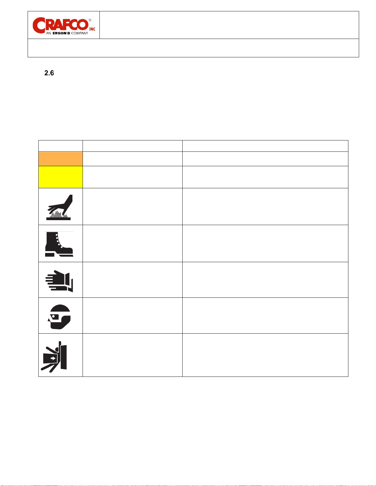
Safety Symbols and Notices
Important safety symbols and notices are marked on the machine and in this manual. Failure to
comply could result in equipment damage, operational malfunction, severe injury, or death. Please
read and comply with all symbols and notices. The table below includes the most commonly used
symbols and notices.
Table 2-1 Safety Symbols and Notices
Symbol
Item
Remarks
WARNING
Warning
Refers to possible bodily injury or death.
CAUTION
Caution
Refers to possible equipment damage or
operational malfunction.
Severe Burn Hazard
Hot material can cause severe burns.
Protective Shoes
Wear hard-soled work shoes.
Protective Gloves
Wear heat resistant gloves.
Protective Face or Eye Wear
Wear face shield or safety glasses.
Body Crush Hazard
Do not stand between trailer and hitch when
hooking melter to truck.

Patcher 4 Operator/Part
Manual
Chapter 2 Safety Precautions
©2023 by Crafco, Inc. All Rights Reserved………...……………………………………………….…Safety Precautions 2-4
Table 2-2 Safety Symbols and Notices (continued)
Symbol
Item
Remark
Crush Hazard
Keep feet and legs clear.
Pinch Hazard
Keep hands and feet clear.
Moving Machinery
Never reach into moving machinery.
Exhaust Hazard
Avoid breathing engine exhaust.
Noise Hazard
Ear protection is advisable.
Read Manual
Read and understand operator and safety
manuals before operating machine.
Table of contents
Other Ergon Construction Equipment manuals


Popular Construction Equipment manuals by other brands


Ammann
Ammann APF 12/40 Translation of the original operating instructions

Toro
Toro MMXD-958H-S Operator's manual

AIRLESSCO
AIRLESSCO SureStripe 4000 Service & operation manual

Komatsu
Komatsu D61EX-12 Operation and maintenance manual

Manitowoc
Manitowoc MLC650 Service maintenance manual

Equipment Technologies
Equipment Technologies APACHE AS740 Operator's manual


