ERICHSEN LINEARTESTER 249 User manual

Scratch Hardness Tester LINEARTESTER 249 1
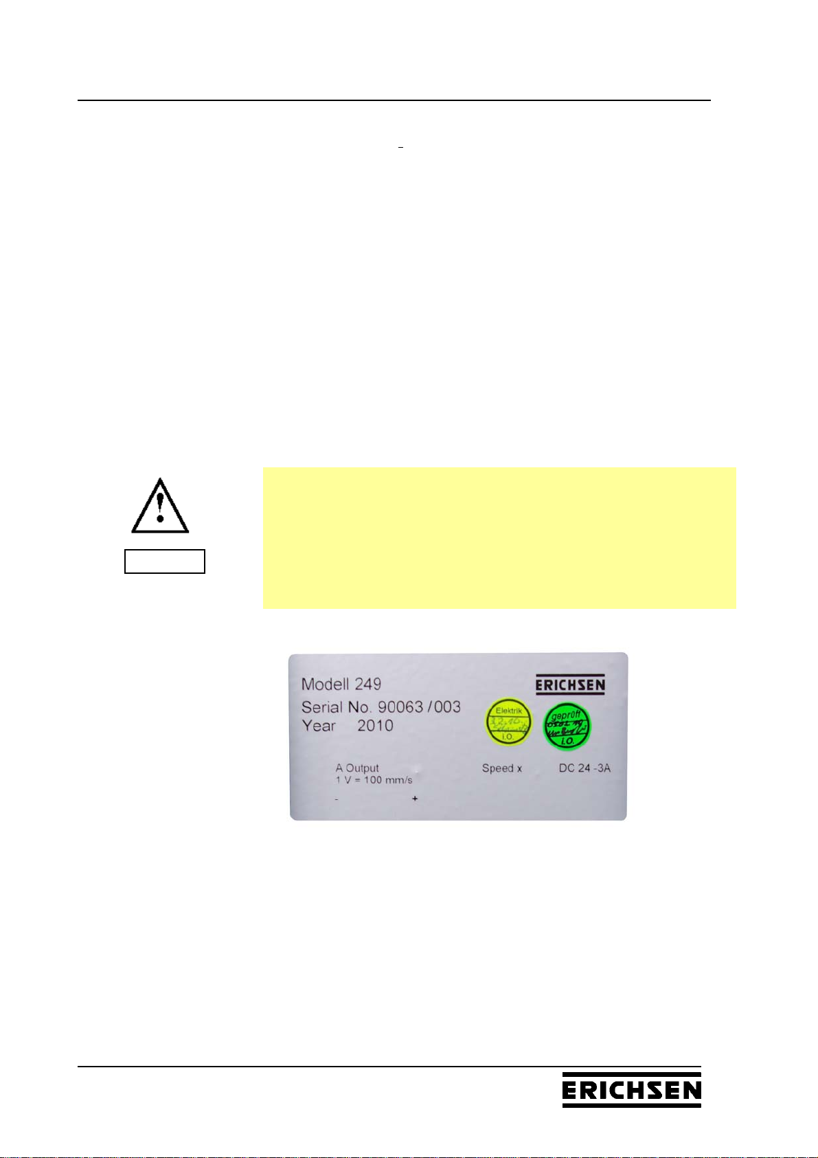
BAE 249
ATTENTION
Read Operating Instructions carefully before commissioning.
Seria-No.:
Erichsen-No.:
Year of construction: 2010
Country of origin: Germany
Stand: VI/2010
Operating Instructions
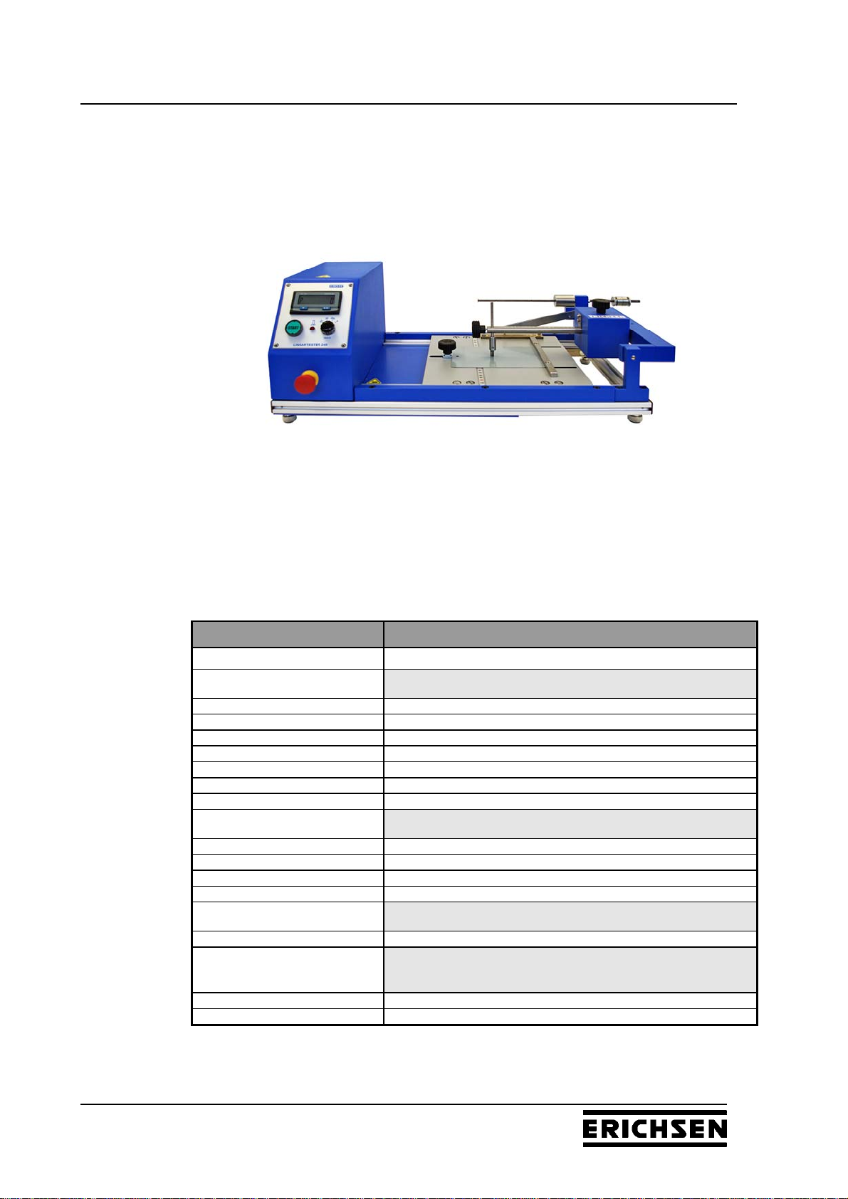
Scratch Hardness Tester
LINEARTESTER 249

Scratch Hardness Tester LINEARTESTER 249 2
BAE 249
Index Page
1. Fundamentals 4
1.1 Who should have access to the Manual 4
1.2 Duties of the user's management 4
1.3 Duties of the user's operators 4
1.4 Dangers arising from the use of the instrument 5
1.5 Proper Use 5
1.6 Guarantee and Liability 5
1.7 Copyright 6
1.8 Address of the Manufacturer 6
2. Safety Instructions 7
2.1 Meaning of Symbols 7
2.2 Availability of Safety Information 7
2.3 Training of Personnel 7
2.4 Dangers from Electrical Energy 8
2.5 Points of Special Danger 8
2.6 Care, Maintenance, Correction of Faults 8
2.7 Modifications to the Equipment 8
2.8 Cleaning of the Instrument and Disposal of Materials 8
3. Transport and Storage 9
3.1 Packing 9
3.2 Checks on Receipt by the User 9
3.3 Reporting Transport Damage and Documentation 9
3.4 Storage 9
4. Instrument Data 10
4.1 Name / Type 10
4.2 Scope of supply 10
4.3 Accessories and Spare Parts 10
4.4 Technical Data 11
4.4.1 Dimensions 11
4.4.2 Technical Data 11
4.5 Noise Level 11
5. Assembly and Commissioning 12
5.1 Installation of the Instrument 12
5.2 Preparation of Energy and Supply Connections 12
5.3 Control elements 14
6. Performance of the Scratch Tests 16
6.1 Selection of Test Tools 16
6.2 Single Scratch Test 18
6.3 Double stroke tests 22

Scratch Hardness Tester LINEARTESTER 249 3
BAE 249
7Preselection Counter (Display) 23
7.1 Control Elements 23
7.2 Operation of the preselection counter 24
7.3 Battery change (Preselection counter) 25
8Universal Adapter Set (Accessories) 26
8.1 Universal shaft 26
8.2 Clamping adapter 26
8.3 Disc adapter 27
8.4 Chucking adapter 27
8.5 Mounting instructions for the universal adapter set 28
9. Care and Maintenance 29
9.1 Inspection and Maintenance 29
9.1.1 Basic Unit 29
9.1.2 Test Tools 29
9.2 Cleaning Material 29
9.3 Disposal of Materials 29
9.4 Customer Service 29
Encl.: Declaration of Conformity

Scratch Hardness Tester LINEARTESTER 249 4
BAE 249
1. Fundamentals
1.1 Who should have access to the Manual
It is a fundamental precondition for safe and trouble-free
operation of the instrument that the safety instructions and
safety guidelines are known by all concerned.
This instruction manual contains the most important guidelines
for the safe operation of the instrument.
The contents of this instruction manual and especially the
safety guidelines must be observed by all persons who work
with the instrument.
In addition all local safety regulations and instructions for
accident and prevention must be observed.
1.2 Duties of the user's management
It is the user's management's duty:
a) only to permit persons to work on the machine who
are familiar with the regulations for safety at work and
accident prevention and who have been trained to operate the
instrument, and
who have read the Chapter on Safety and the warnings given
in this instruction manual and have understood what they have
read and have confirmed this by signing a statement to that
effect, and
b) to check at regular intervals that personnel are aware of the
essential need for a safe working
1.3 Duties of the user's operators
All persons whose duty it is to work with the instrument must
before starting work:
take note and follow the fundamental instructions for safe
working and accident prevention
read the Safety Instructions chapter and warnings given in this
instruction manual and to confirm that they have done this and
have understood what they have read with their signature.

Scratch Hardness Tester LINEARTESTER 249 5
BAE 249
1.4 Dangers arising from the use of the instrument
The instrument is built in accordance with the state of technology
and the recognised safety regulations. In spite of this, dangers to life
and limb can arise for the user or third parties. Damage on the
instrument of other objects can arise in its use. The instrument must
only be used:
for the application for which it is intended.
with all safety features in fault-free condition.
Faults that could influence safety must be corrected immediately.
1.5 Proper Use
The Scratch Hardness Tester LINEARTESTER 249, is intended for
determining the scratch resistance of protective surface coatings,
such as paint and lacquer finishes, plastic coatings etc.
Also for other tests:
Scribe/Scratch tests, to and fro-cycle abrasion tests, Crockmeter
tests, MEK tests, tests determining the resistance against solvents in
general or wipe test, respectively.
If the instrument is employed for any other purposes, this will be
improper use. Erichsen GmbH & Co. KG will not be liable for any
damage resulting from this.
Proper use also implies:
observance of all guidelines contained in the instruction manual
and
full attention to laid down inspection and maintenance
procedures.
1.6 Guarantee and Liability
Fundamentally our general Conditions of Sale and Supply apply.
These will be available to the user at the latest at the time of
completion of the contract. Claims under guarantee or liability in the
event of injury to persons or damage to equipment cannot be
accepted if these are the result of one or more of the following
causes:
- Improper use of the instrument.
- Incorrect assembly, commissioning, operation and maintenance of
the instrument.
- Operation of the instrument when safety equipment was faulty or
incorrectly fitted.
- Failure to observe guidelines in the instruction manual in respect
of transport, storage, assembly, commissioning, operation,
maintenance, and setting up the instrument.
- Unauthorised modifications to the instrument
- Inadequate monitoring of parts of the instrument that are subject
to wear, or incorrectly made repairs.
- Catastrophic damage caused by external effects or force majeur.

Scratch Hardness Tester LINEARTESTER 249 6
BAE 249
1.7 Copyright
The copyright of this instruction manual remains with ERICHSEN
GmbH & Co. KG, D-58675 Hemer. The instruction manual is
intended solely for the user and his personnel.
The instruction manual contains instructions and guidelines that
may not be duplicated, distributed or otherwise passed on either in
full or in part.
Infringement of these restrictions can lead to criminal prosecutions.
1.8 Address of the Manufacturer
ERICHSEN GmbH & Co. KG
Am Iserbach 14
D-58675 HEMER
Tel.: +49(0) 2372 96 83-0
Fax: +49(0) 2372 6430
Internet: http://www.erichsen.de

Scratch Hardness Tester LINEARTESTER 249 7
BAE 249
2. Safety Instructions
2.1 Meaning of Symbols
The following symbols for dangers are used in this instruction
manual.
2.2 Availability of Safety Information
The instruction manuals must always be kept at the place of
operation of the instrument.
In addition to the information contained in the instruction
manual, general and local regulations for accident
prevention and environmental protection shall be kept
available and observed.
• It is essential to ensure that all guidelines in respect of
safety and dangers on the instrument are kept in readable
condition.
2.3 Training of Personnel
Only properly trained personnel may operate the instrument.
Who is responsible for what must be clearly established in
respect of installation, commissioning, operation, setting up
maintenance and repair.
Personnel in training must only be allowed to work on the
instrument when supervised by an experienced person.
This symbol means possible immediate danger to the life or
health of personnel.
If this guideline is not noted it can lead to severe danger to
health, up to fatal injury.
This signal signifies a situation that could be dangerous.
Non observance of this guideline can lead to injury or to
damage to equipment.
This symbol draws the attention to special tips for the user and
information that is particularly useful.
•It refers to aspects which will enable you to use your
Instrument to optimum effect.
Dan
g
e
r
Warnin
g

Scratch Hardness Tester LINEARTESTER 249 8
BAE 249
2.4 Dangers from Electrical Energy
Work on the electrical supply may only be done by
qualified electrician.
The electrical equipment of the instrument must be checked
regularly. Loose connections and cable damaged by heat
must be corrected immediately.
2.5 Points of Special Danger
2.6 Care, Maintenance, Correction of Faults
Carry out maintenance and inspection at the correct
intervals.
Inform operating personnel before starting with
maintenance or repair work.
The instrument must be isolated from the elctrical supply
whenever maintenance, inspection or repair work is done.
2.7 Modifications to the Equipment
No modifications or additions or alterations to the instrument
may be made without permission from the manufacturer.
All measures involving modifications require written
confirmation of approval from ERICHSEN GmbH & Co. KG
Instruments not in fault-free condition must be switched off
immediately.
Use only replacement parts from the original supplier.
- If parts from other sources are used there is no guarantee
that they are designed to take the loading and meet the
safety requirements.
2.8 Cleaning of the Instrument and Disposal of Materials
Materials must always be used and disposed of correctly.
This applies particularly when cleaning with solvents.
There is a special point of danger in the working area of the
instrument:
Do not move hands into the radius of action of the working
stylus.
Dan
g
e
r

Scratch Hardness Tester LINEARTESTER 249 9
BAE 249
3. Transport and Storage
3.1 Packing
One of the factors on which the type of packing depends is the
method of transport involved. Unless otherwise agreed in the
Contract, the packing will be in accordance with the HPE guidelines
laid down by the Federal Association for Timber, Pallet and Export
Packing (German registered association) and from the German
Association of Machine Builders.
Note must be taken of the pictorial symbols on the packing.
3.2 Checks on Receipt by the User
Check packing for damage
After unpacking check complete supply.
3.3 Reporting Transport Damage and Documentation
Reports of damage should be documented as accurately as
possible (possibly photographed) and reported to the relevant
insurers or, in the case of sales "delivered to customers works",
to the supplier.
3.4 Storage
The instrument must be stored in a dry place at a temperature
between 10 - 40°C (if possible in the original packing).
Scratch Hardness Tester LINEARTESTER 249 10
BAE 249
4.InstrumentData
4.1 Name / Type
Scratch Hardness Tester LINEARTESTER 249
Ord.-No. 0263.01.31
4.2 Scope of supply
1 Basic unit
1 Circular level
1 Power pack
1 Operating manual
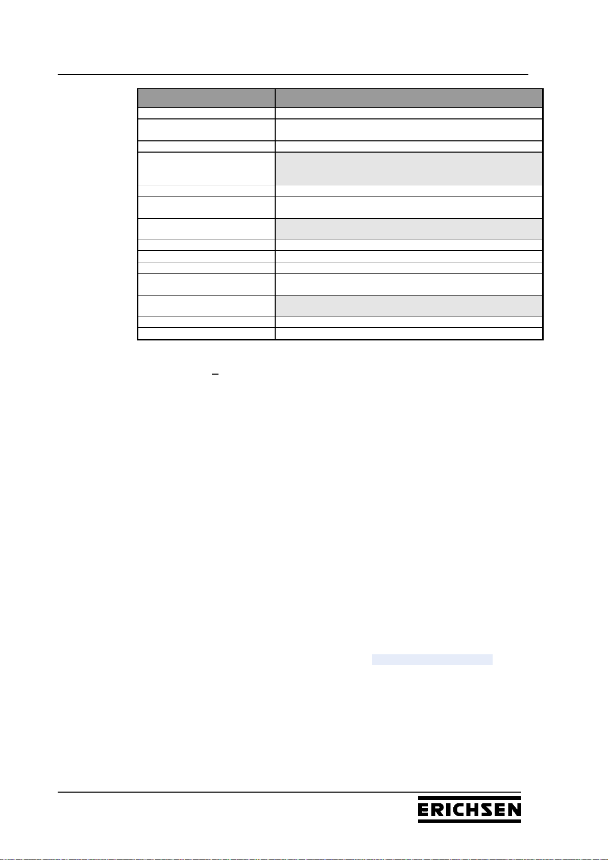
4.3 Accessories and Spare Parts
Ord.-No. Product Description
0839.01.32 Load weight (1 - 40) N
Test Tip with long shaft
915030241 Test tip acc. to Clemen (R 1.0 mm)
0693.01.32 Test tip acc. to van Laar (Ø 0.5 mm)
0842.01.32 Test tip acc. to IHD (Ø 0.6 mm)
0208.02.32 Test tip acc. to ISO (Ø 1.0 mm)
915030441 Test tip acc. to VW (3 mm/60°)
0741.01.32 Test tip acc. to (0.5 mm/90°)
0740.01.32 Test tip acc. to (1.0 mm/90°)
Equipment for MEK test
0840.01.32 MEK-Attachment
0841.01.32 Test plugs made of high dense special felt (per 100 pcs.)
0849.01.32 Test set for MEK test
0364.08.53 Crocking cloth (per 1000 pcs.)
Universal adapter set and accessories
0690.01.32 Universal Adapter Set
Spherical inserts for the clamping adapter (short
shaft without clamping device)
0539.01.32 Test tip acc. to van Laar (Ø 0.5 mm)
0539.02.32 Test tip acc. to Bosch (Ø 0.75 mm)
Scratch Hardness Tester LINEARTESTER 249 11
BAE 249
Ord.-No. Product Description
0539.03.32 Test tip acc. to ISO (Ø 1.0 mm)
0539.07.32 Test tip acc. to ISO (Ø 1.0 mm) – additionally covered with an
extremly hard layer
0539.04.32 Test tip acc. to BMW (Ø 3.0 mm)
Asymmetric inserts (short shaft with clamping
device)
0218.02.32 Test tip acc. to Clemen (R 1.0 mm)
0564.01.32 Test Tip for cross hatch cutting (30°) – additionally covered with
an extremly hard layer
Inserts (Ø 16 mm/R 0.5 mm) for the disc adapter
0430.01.32 Test discs made of Duroplast (p. 10 pcs.)
0430.02.32 Test discs made of copper (p. 10 pcs.)
0430.03.32 Test discs made of stainless steel (p. 10 pcs.)
0539.05.32 Test discs made of stainless steel, additionally covered with an
extremly hard layer (p. 10 pcs.)
Adapter for abrasion tests
0844.01.32 Squarish adapter (egde length 25 mm)
0845.01.32 Cylindrical adapter (dia. 25 mm)
4.4 Technical Data
4.4.1 Dimensions
Width: approx. 280 mm
Length: approx. 580 mm
Height: approx. 210 mm
Net weight: approx. 13 kg
4.4.2 Technical Data
Power supply: (100 - 240) VAC, (47 - 63) Hz
Power consumption: 25 VA
Scratch force: - range: (0,5 - 20) N *)
- increment: 0,5 N *)
- accuracy: 0,2 N *)
Test speed: 22/35/200 mm/s (fixed)
(20 - 200) mm/s programmable
Test distance: 60 mm
Specimen dimensions max. 150 x 210 mm (DIN A 5) **)
Length of cycles: 60/110 mm (with/without guide plate)
*)Using the 40 N load weight (optional) all force levels doubles up.
**)Only flat specimens can be tested.
4.5 Noise Level
The continuous noise level from the instrument does not exceed
<70 dB(A).
Scratch Hardness Tester LINEARTESTER 249 12
BAE 249
5. Assembly and Commissioning
5.1 Assembly of the Instrument
The Scratch Hardness Tester LINEARTASTER 249 is a table
model, which must be installed in a suitable place with normal
ambient temperature. Special fixings are not required.
To align the instrument horizontally use the four adjustable leveling
feet at the bottom of the device as well as the included spirit level.
5.2 Preparation of Energy and Supply Connections
For the power supply please use the delivered power pack 24V 3A
only.
• Connect the low tension jack (c) to the instrument.
• Connect mains plug to the AC mains supply.
Prior to connecting the instrument check whether the voltage
indicated on the name plate corresponds to the local mains
voltage.
If these ratings are not compatible, the instrument should under
no circumstances be connected!
The input voltage range is 100 V AC – 240 V AC. Please make
sure that this range is not exceeded.
Attention

Scratch Hardness Tester LINEARTESTER 249 13
BAE 249
Rear panel of the housing
A out
1V=100mm/s Speed X
DC 24V-3A
+
-
LINEARTESTER 249
a Potentiometer for speed setting
b Analogue output
c Low tension jack
The analogue output (b) consists of two telephone jacks (black =
pole / red = +pole).
The analogue output is short-circuit proof and must be connected to a
commercial digital voltmeter <2% and an input resistance >
1 MOhm. Adjust the measuring range to 2 V DC (direct current).
The test weight with the test tip must be lifted safely.
Set the preselection counter to a value of >50 strokes to have time
enough available for the adjusting procedure.
Reasonable values for the speed are recommended in the range of
10 mm/s to 190 mm/s (resolution: 1 V – 100 mm/s; medium test
speed with an accuracy of ±2.5 %.
The 15-gear potentiometer (a) serves for the setting of the speed.
With the help of a calibration screw driver and the reading of the
proportional analogue output voltage it is possible to adjust the speed
simply and precisely.
b a c

Scratch Hardness Tester LINEARTESTER 249 14
BAE 249
5.3 Control elements
1 Main switch EMERGENCY-OFF
2 Slide
3 Test tip
4 Limit stop / Movable clamping bar
5 Counterpoised lever with scale
6 Taring weight
7 Weight block with locking screw
8 Weight of 0.5 N
9 Fastening screw for test tip
10 Clamp screw for fixing the test panel
11 Setting test speed
12 LED display
13 Start key
14 Visual through-cutting signal
15 Scratch guide plate
16 Scratch depth adjusting groove
17 Rest position of sliding guide ball
18 Sliding guide ball
19 Ruler

Scratch Hardness Tester LINEARTESTER 249 15
BAE 249
1 2
3
4 5
6
7
8
9
10
11
12
13
14
19
18
16
15
17

Scratch Hardness Tester LINEARTESTER 249 16
BAE 249
6. Performance of the Scratch Tests
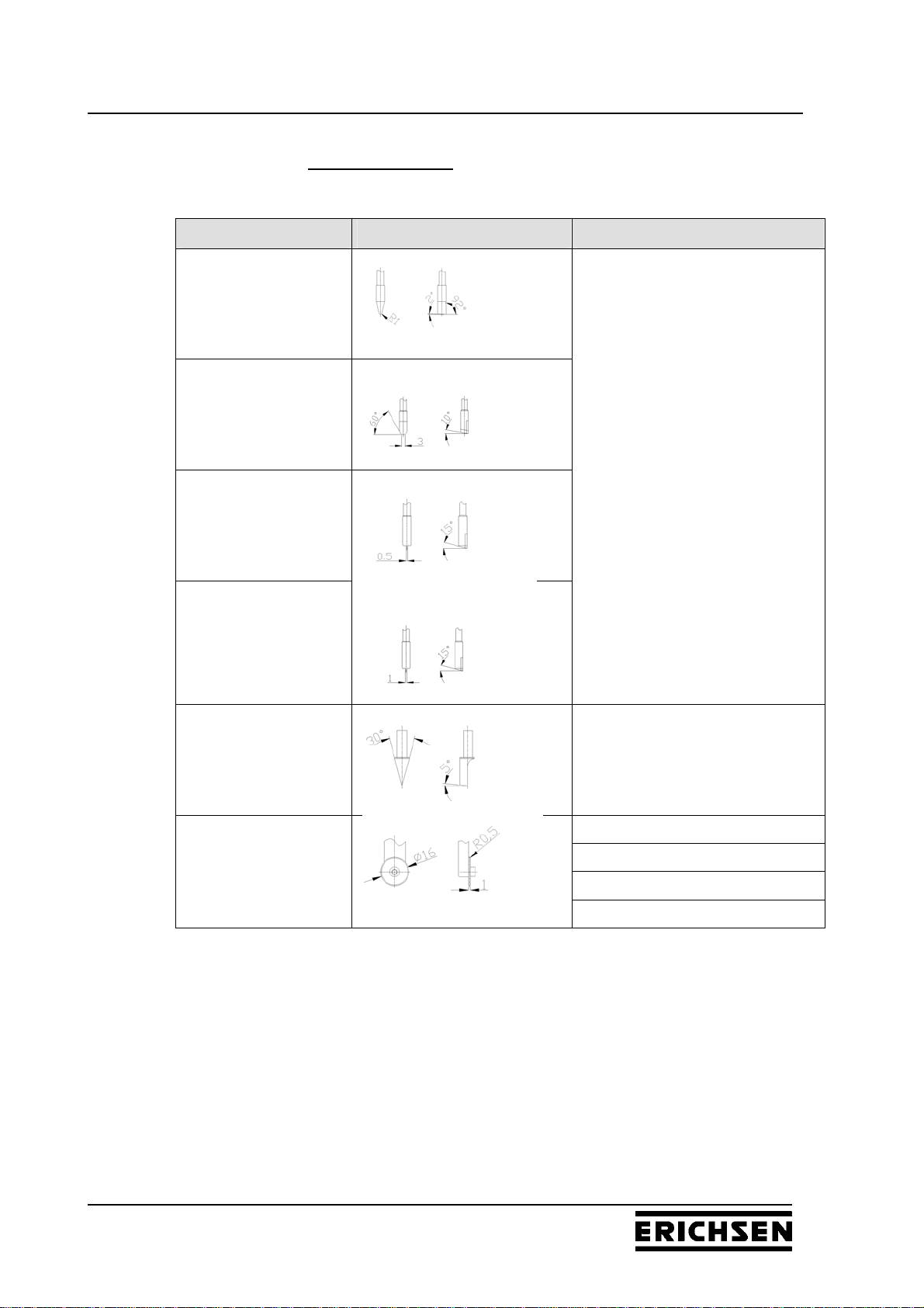
6.1 Selection of Test Tools
For the performance of scratch hardness tests with the
LINEARTESTER 249 following test tools are available:
Spherical Inserts
Description Test geometry Material
test tip
acc. to van
Laar 1) 2)
test tip
acc. to IHD 1)
carbide insert
test tip
acc. to Bosch 2)
test tip
acc. to ISO 1) 2)
carbide insert *)
test tip
acc. to BMW 2)
hardened
steel
*)additionally covered with an extremly hard layer
1) long shaft, directly assembled
2) short shaft, only for using with the adapter set
3) only for using with the disc adapter of the universal adapter set
Scratch Hardness Tester LINEARTESTER 249 17
BAE 249
Asymmetric Inserts
Description Test geometry Material
test tip
acc. to
Clemen 1) 2)
test tip
acc. to VW 1)
carbide insert
test tip
acc. to
Sikkens 1)
test tip
acc. to
Sikkens 1)
test tip for
cross hatch cutting 2)
hardened
steel *)
duroplast
copper
stainless steel
test disc
acc. to
Oesterle 3)
stainless steel *)
*)additionally covered with an extremly hard layer
1) long shaft, directly assembled
2) short shaft, only for using with the adapter set
3) only for using with the disc adapter of the universal adapter set

Scratch Hardness Tester LINEARTESTER 249 18
BAE 249
Fig. 1
Fig. 2
Fig. 3
Fig. 4a
Fig. 4b
6.2 Single Scratch Test
Loosen clamp screw (10) for fixing the
specimen and draw it backwards.
Loosen movable clamping bar/ limit stop (4) and
draw it backwards (if desired, tighten it in this
position or in any other). (Fig. 1)
Place test panel onto the slide (2) and push it
against the clamping bar / limit stop (4). (Fig.2)
Fix test panel with the clamp screw for fixing the
specimen (10). (Fig.3)
Place weight block (7) into zero position and fix
it with the locking screw. (Fig. 4a/4b)

Scratch Hardness Tester LINEARTESTER 249 19
BAE 249
Fig. 5
Fig. 6
Fig. 7a
Fig. 7b
Fig. 8
Move the weight of 0.5 N (8) to the right into
the zero position (clicks into place behind).
(Fig.5)
Insert test tip (3), according to the correct
direction of effect, into the corresponding holder
in the counterpoised beam (5) and fix it slightly
with the fastening screw (9). (Fig.6)
Then set the sliding guide ball (18) into the
scratch depth adjusting groove (16) of the
scratch guide plate (15).
At this the fastening screw (9) must be loosened
again, so that the test tool rests on the test
panel. (Fig. 7a)
Now tighten the fastening screw (9) finally.
(Fig.6)
Then lift the counterpoised lever (5) for a
moment using the fastening screw (9) and
replace it immediately.
At this the sliding guide ball (18) automatically
jumps from the scratch depths adjusting groove
(16) into the rest position (17) of the guide plate
(15). (Fig.7b)
The tip of the test tool (3) is now located in a
“pending / resting position” just over the test
panel.
Adjust the position of the taring weight by
turning so that the weight of the test tip (3) is
compensated and the counterpoised lever (5)
shows already a corresponding upward trend
when it is slightly touched. (Fig. 8)

Scratch Hardness Tester LINEARTESTER 249 20
BAE 249
Fig. 9a
Fig. 9b
Fig. 10
Fig. 11a
Fig. 11b
Fig. 11c
Now set the required test force by moving the
weight block (7) along the scale on the
counterpoised lever (5) (steps of 1 N).
(Fig. 9 a/9b)
By moving the weight of 0.5 N (8) to the left
into the first catching position the test force is
increased by 0.5 N, when moving further into
the next catching position by totally 1 N.
(Fig. 10)
Now push the left arrow key under the display
(12) until “P” (programme/preset) appears on
the left side of the display. (Fig. 11a)
Then set the number „1“ (= 1 double stroke
cycle) using the left and the right key. (Fig. 11b)
Now push the left key again so that „C“(cycles
completed) instead of „P“ appears on the left
side of the display.(Fig. 11c)
(see page 25 – Operation of the preselection counter)
Table of contents
Other ERICHSEN Test Equipment manuals


