ERICSON EDACS LBI-39153 User manual

LBI-39153
ericssonzericssonz
MAINTENANCE MANUAL
EDACSCOMPACT VERTICAL VOTER
SYSTEM INSTALLATION AND SERVICE
TABLE OF CONTENTS
Section/Paragraph..........................................................................................................................................Page
TABLE OF CONTENTS................................................................................................................................1
INTRODUCTION...........................................................................................................................................5
RELATED PUBLICATIONS........................................................................................................................5
RECOMMENDED TEST EQUIPMENT AND ACCESSORIES...............................................................5
INSTALLATION............................................................................................................................................6
SITE PREPARATION...............................................................................................................................6
Equipment Location............................................................................................................................6
Equipment Room Grounding..............................................................................................................6
Operating Environment.......................................................................................................................6
Electrical Power..................................................................................................................................6
Telephone Service ..............................................................................................................................6
UNPACKING EQUIPMENT....................................................................................................................7
VOTER CABINET RACK-UP..................................................................................................................7
POWER DISTRIBUTION ........................................................................................................................7
GETC CONFIGURATION............................................................................................................................8
GETC PERSONALITY PROGRAMMING..............................................................................................8
COMPACT VERTICAL VOTER CONFIGURATION..............................................................................9
SIMULCAST SYSTEM CONFIGURATION...........................................................................................9
Hardware Installation:.........................................................................................................................9
STEP 1 - EDACS DIGITAL INTERFACE PANEL CONFIGURATION................................................9
STEP 2 - BACKPLANE CONFIGURATION ..........................................................................................11
STEP 3 - ROCKWELL MODEM INTERFACE CARD CONFIGURATION .........................................12
STEP 4 - DIGITAL RECEIVER CONFIGURATION..............................................................................13
STEP 5 - SELECTOR CONFIGURATION..............................................................................................13
STEP 6 - VOTER SOFTWARE INSTALLATION ..................................................................................14
Equipment Required ...........................................................................................................................14
POST CONFIGURATION CHECKS .......................................................................................................15
CARD CONFIGURATION GUIDE (350A1612).........................................................................................16
USING THE SLOT CONFIGURATION TABLES..................................................................................16
Simulcast Systems (VP1-5 = S)..........................................................................................................16
Voted Systems (VP1-5 = V)...............................................................................................................16
CONFIGURATION TABLES...................................................................................................................18

LBI-39153 TABLE OF CONTENTS
2
TABLE OF CONTENTS
Section/Paragraph..........................................................................................................................................Page
SYSTEM ALIGNMENT.................................................................................................................................31
SYSTEM SETUP LEVELS.......................................................................................................................31
ANALOG VOTER ALIGNMENT PROCEDURE....................................................................................31
Setup ...................................................................................................................................................31
CV2FIELD ALIGNMENT PROCEDURE................................................................................................31
Setup ...................................................................................................................................................31
RMIC Modem Levels..........................................................................................................................31
SYSTEM CHECKOUT..................................................................................................................................32
MAIN SITE GETC....................................................................................................................................32
SATELLITE RECEIVER ..........................................................................................................................32
SIMULCAST TX SITE .............................................................................................................................33
VOTER SYSTEM CHECKOUT...............................................................................................................33
TROUBLESHOOTING..................................................................................................................................35
CABLE CONNECTION LISTS.....................................................................................................................39
CABLE CONNECTION LISTS CONNECTION LIST 350A1711, 2 TO 12 SITE CV2SYSTEM
(1 CHANNEL PER SHELF)......................................................................................................................39
CONNECTION LIST 350A1712, 2 TO 17 SITE CV2SYSTEM (1 CHANNEL PER SHELF)...............41
CONNECTION LIST 350A1710, 2 TO 6 SITE CV2SYSTEM (2 CHANNEL PER SHELF).................44
DC POWER DISTRIBUTION CABLE LISTS, 350A1713......................................................................47
Main Cabinet Power Source................................................................................................................47
Expansion Cabinet Power Source .......................................................................................................47
DC Power Distribution to Voter Units................................................................................................48
ANALOG AND DIGITAL VOTER CROSS-CONNECT PANEL CONNECTION LIST......................49
Analog Connections............................................................................................................................49
Digital Connections, Simulcast...........................................................................................................51
Digital Connections, Voted.................................................................................................................53
CABLE DIAGRAMS......................................................................................................................................55
PARTS LISTS..................................................................................................................................................73
83-INCH VERTICAL CABINET..............................................................................................................73
86-INCH OPEN RACK .............................................................................................................................73
VOTER EQUIPMENT ..............................................................................................................................73
ASSEMBLY DIAGRAMS..............................................................................................................................75
INTERCONNECTION DIAGRAMS............................................................................................................81
Copyright February 1996, Ericsson Inc.

TABLE OF CONTENTS LBI-39153
3
FIGURES AND TABLES
Page
Figure 1 - ROA 117 2228 Header Pinouts...............................................................................................................9
Figure 2 - ROA 117 2227 Header Pinouts...............................................................................................................11
Figure 3 - Backplane Jumper Locations...................................................................................................................11
Figure 4 - RMIC Jumper Locations..........................................................................................................................12
Figure 5 - DIP Switches S1 thru S3..........................................................................................................................13
Figure 6 - RMIC DIP Switch S1.............................................................................................................................. 31
Table 1 - Telco Cable Lengths.................................................................................................................................6
Table 2 - Simulcast 1-Channel/Shelf Interface Panel and Backplane Jumpers ........................................................10
Table 3 - Simulcast 1-Channel/Shelf Interface Panel Jumpers J40 and J41............................................................. 10
Table 4 - Simulcast 2-Channel/Shelf Interface Panel and Backplane Jumpers ........................................................10
Table 5 - Digital Receiver Time Slot Settings.......................................................................................................... 13
Table 6 - Information in VP1...................................................................................................................................17
Table 7 - Number values for letters for VP1-6, 7, 8, 10, & 15................................................................................. 17
Table 8 - Information in VP2...................................................................................................................................17
Table 9 - Information in VP3...................................................................................................................................18
Table 10 - Digital Voter Configuration, Simulcast, 2 to 6 RS232 Sites, 2 Channels/Shelf, no RM Sites................ 19
Table 11 - Analog Voter Configuration, Simulcast, 2 to 6 RS232 Sites, no RM Sites ............................................19
Table 12 - Digital Voter Configuration, Simulcast, 2 to 5 RS232 Sites, 2 channels/shelf, One RM Site................. 20
Table 13 - Analog Voter Configuration, Simulcast, 2 to 5 RS232 Sites, One RM Site ........................................... 20
Table 14 - Digital Voter Configuration, Simulcast, 1 channel/shelf, 2 to 12 RS232 Sites and no RM Sites ...........21
Table 15 - Analog Voter Configuration, Simulcast, 2 to 12 RS232 Sites and no RM Sites..................................... 21
Table 16 - Digital Voter Configuration, Simulcast, 1 channel/shelf, 13 to 17 RS232 Sites and no RM Sites .........22
Table 17 - Analog Voter Configuration, Simulcast, 13 to 17 RS232 Sites and no RM Sites................................... 22
Table 18 - Digital Voter Configuration, Simulcast, 1 channel/shelf, 2 to 11 RS232 Sites and One RM Site .......... 23
Table 19 - Analog Voter Configuration, Simulcast, 2 to 11 RS232 Sites and One RM Site.................................... 23
Table 20 - Digital Voter Configuration, Simulcast, 1 channel/shelf, 12 to 15 RS232 Sites and One RM Site ........ 24
Table 21 - Analog Voter Configuration, Simulcast, 12 to 15 RS232 Sites and One RM Site.................................. 24
Table 22 - Digital Voter Configuration, Simulcast, 1 channel/shelf, 2 to 10 RS232 Sites and Two RM Sites........ 25
Table 23 - Analog Voter Configuration, Simulcast, 2 to 10 RS232 Sites and Two RM Sites .................................25
Table 24 - Digital Voter Configuration, Simulcast, 1 channel/shelf, 11 to 13 RS232 Sites and Two RM Sites...... 26
Table 25 - Analog Voter Configuration, Simulcast, 11 to 13 RS232 Sites and Two RM Sites ...............................26
Table 26 - Digital Voter Configuration, Simulcast, 1 channel/shelf, 2 to 9 RS232 Sites and Three RM Sites........ 27
Table 27 - Analog Voter Configuration, Simulcast, 2 to 9 RS232 Sites and Three RM Sites .................................27
Table 28 - Digital Voter Configuration, Simulcast, 1 channel/shelf, 10 or 11 RS232 Sites and Three RM Sites....28
Table 29 - Analog Voter Configuration, Simulcast, 10 or 11 RS232 Sites and Three RM Sites.............................28
Table 30 - Voted, 2 Channel, RM Connected.......................................................................................................... 29
Table 31 - Voted, 1 Channel, RM Connected.......................................................................................................... 29
Table 32 - Voted, 2 Channel, RS232 Connected .....................................................................................................29
Table 33 - Voted, 1 Channel, RS232 Connected .....................................................................................................30

LBI-39153 TABLE OF CONTENTS
4
FIGURES AND TABLES
Page
Table 34 - LED Indicators for Trunked Idle Channels.............................................................................................32
Table 35 - LED Indicators for Trunked Assigned Channels ....................................................................................32
Table 36 - LED Indicators for Failsoft Idle Channels ..............................................................................................32
Table 37 - LED Indicators for Failsoft Assigned Channels......................................................................................32
Table 38 - LED Indicators for Satellite Site Receivers ............................................................................................33
Table 39 - LED Indicators for Simulcast TX Site GETC.........................................................................................33
Table 40 - 2 To 12 Site CV2System (1 Channel Per Shelf) Cable Connection List.................................................39
Table 41 - 2 To 17 Site CV2System (1 Channel Per Shelf) Cable Connection List.................................................41
Table 42 - 2 To 6 Site CV2System (2 Channel Per Shelf) Cable Connection List...................................................44
Table 43 - Main Cabinet Power Source....................................................................................................................47
Table 44 - Expansion Cabinet Power Source...........................................................................................................47
Table 45 - 24 Vdc Power Distribution .....................................................................................................................48
Table 46 - 5/12 Vdc Power Distribution ..................................................................................................................48
Table 47 - 12 Vdc Power Distribution for 2 Channel per Shelf Systems Only.........................................................48
Table 48 - Analog Connections For a Two Channel/Shelf Voter, 2-6 Sites.............................................................49
Table 49 - Analog Connections For a One Channel/Shelf Voter, 2-12 Sites............................................................50
Table 50 - Analog Connections For a One Channel/Shelf Voter, 2-17 Sites............................................................50
Table 51 - Digital Connections, Two Channels/Shelf, Simulcast or Voted, RS-232 Connected, 2-6 Sites.............51
Table 52 - Digital Connections, One Channel/Shelf, Simulcast or Voted, RS-232 Connected, 2-12 Sites..............51
Table 53 - Digital Connections, One Channel/Shelf, Simulcast or Voted, RS-232 Connected, 2-17 Sites..............52
Table 54 - Digital Connections, Two Channels/Shelf, Voted, Rockwell Modem Connected, 2-4 Sites ..................53
Table 55 - Digital Connections, One Channel/Shelf, Voted, Rockwell Modem Connected, 2-9 Sites.....................54

INTRODUCTION LBI-39153
5
INTRODUCTION
This manual contains maintenance information for the
Enhanced Digital Access Communication System
(EDACS) Compact Vertical Voter (CV2) system. The
information presented covers Voter equipment used in
Simulcast or Voted (Non-Simulcast) systems.
Included in this manual are the following sections:
• Installation Instructions
• Voter Configuration Procedures
• Card Configuration Guide
• System Alignment
• System Checkout
• Cable connection Lists
• Assembly Diagrams
• Interconnect Diagrams
RELATED PUBLICATIONS
It may be necessary to refer to one or more of the
following maintenance manuals when installing and setting
up the Voter system. These manuals provide additional
information
LBI-38430 - MASTR IIe Station Maintenance
Manual.
LBI-38676 - Analog Voter Maintenance Manual
LBI-38894 - GETC Trunking Card Maintenance
Manual for 19D901868G3 and G4.
LBI-38988 - EDACS Station GETC Configuration
Manual.
LBI-39038 - EDACS Redundant Power Supply
System Maintenance Manual
LBI-39074 - MASTR III EDACS Installation
Manual.
LBI-39075 - EDACS CV2 Interface Panel
Maintenance Manual
LBI-39090 - Simulcast Transmit Site Maintenance
Manuals.
LBI-39112 - MASTR III Multiple Receiver
Maintenance Manual
LBI-39142 - EDACS Voter Cross Connect Panel
Maintenance Manual
LBI-39149 - EDACS Compact Vertical Voter
(CV2) Maintenance Manual
LBI-39150 - EDACS CV2 Digital Voter Shelf
Maintenance Manual
LBI-39151 - EDACS CV2 Digital Receiver &
Selector Maintenance Manual
LBI-39152 - EDACS CV2 Rockwell Modem & RS-
232 Intfc Card Maintenance Manual
LBI-39158 - EDACS Power Distribution Panel
Maintenance Manual
LBI-39186 - Simulcast Control Point Maintenance
Manuals
SRN-1007 - Release Notes for Voter Software
SRN-1060 - Release Notes for GETC 1e
TQ-3357 - Personality Programming Instructions
RECOMMENDED TEST
EQUIPMENT AND ACCESSORIES
The following test equipment is required for alignment
and testing of the Voter system. Items identified by an
asterisk (*) indicate test equipment available in the
Simulcast Test Equipment Rack.
1. *Digital Storage Oscilloscope, configured for rack
mount - Tektronix 2232A or Tektronix TDS 410A
2. *Transmission Test Set - Convex C120
3. *Sweep Analyzer - Hewlett Packard HP 35670A
4. Digital Voltmeter with fine tip leads
5. Eye Pattern Generator - 19A149431P1
6. Inline Modular Adapter (not available from
Ericsson)
• Six Wire Modular Adapter - similar to Harris
“Banjo-6” 10220-100
• Eight Wire Modular Adapter - similar to Harris
“Banjo-8” 10230-100
7. Communications Service Monitor FM/AM 1200S
with Spectrum Analyzer - IFR Systems Inc.
Alternate monitors that may be used include the
IFR 1500 and HP8920A.
7. Test Module Kit, VPTS3X, includes:
NOTE
LBI-39153 INSTALLATION
6
• Digital Voter Extender Card (ROA 117 2249)
• Analog Voter Extender Card (19C317762G2)
• Analog Voter Test Assy Card (19D416003G1)
• Programming (Flash) Cable (19B804346P111)
INSTALLATION
SITE PREPARATION
Equipment Location
In a typical Voter system installation, the CV2system is
co-located with the Simulcast Control Point or Main Site
repeater (Non-simulcast system).
The Interface between the Voter (EDACS Interface
Panel) and other system equipment, such as Satellite
Receivers, IMC, and Main Site repeater, or Simulcast
Control Point equipment is made via the Analog and Digital
Voter Cross Connect panels. Refer to LBI-39142 for
information regarding the cross connect panels.
The Voter system uses standard twenty-five (25) pair
TELCO cables to route the audio and digital signals between
the Voter Interface Panel and the Voter Cross Connect
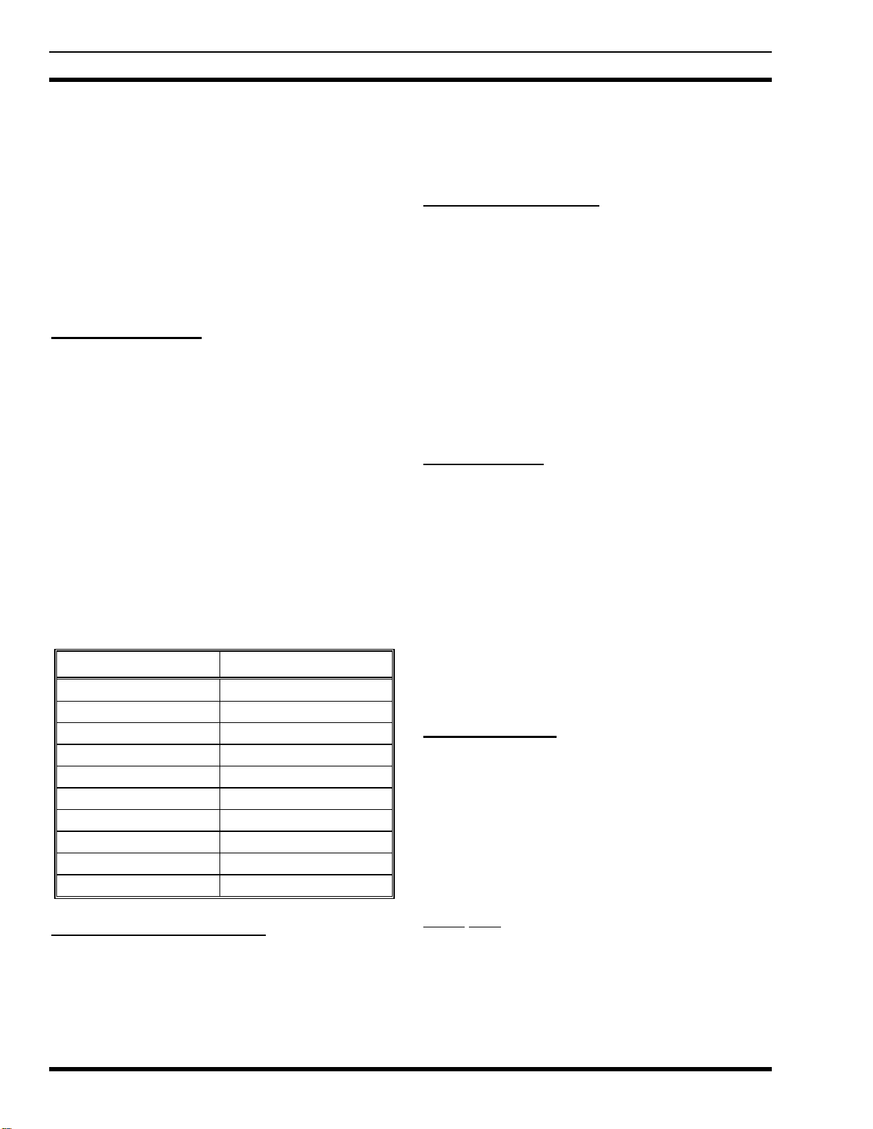
Panels. Table 1 provides the part number for Telco cables
of various lengths.
Table 1 - Telco Cable Lengths
PART NUMBER CABLE LENGTH
19D903880P120 5 feet (1.52 meters)
19D903880P121 15 feet (4.57 meters)
19D903880P122 7 feet (2.13 meters)
19D903880P123 10 feet (3.05 meters)
19D903880P124 20 feet (6.10 meters)
19D903880P125 25 feet (7.62 meters)
19D903880P126 30 feet (9.14 meters)
19D903880P127 35 feet (10.67 meters)
19D903880P128 40 feet (12.19 meters)
19D903880P129 50 feet (15.24 meters)
Equipment Room Grounding
Ensure all equipment and facilities meet the
requirements for grounding and lightning protection.
Installation manual LBI-39067 – Standard For Site
Grounding And Protection provides instructions for proper
grounding of sites and radio equipment. These procedures
should be observed in order to protect the equipment and
service personnel from lightning and other sources of
electrical surges. This manual is not included, but is
available on request from Ericsson Inc.
Operating Environment
The equipment room where the Voter equipment is
installed must meet the environmental conditions listed in
the Specifications section of LBI-39149. Each Voter
cabinet is equipped with an exhaust fan which draws cool air
through the cabinet to dissipate heat.
Although the temperature requirements for individual
pieces of equipment may be broader, when several units are
assembled together in a cabinet more heat is generated.
Because of this condition, the ambient room temperature
outside the cabinet must be lowered to ensure the
temperature inside the cabinet does not exceed the limits for
the equipment.
Electrical Power
Each EDACS cabinet is equipped with its own AC
power cord (except for DC options). Each of these power
cords should be connected to a separate circuit breaker. The
following circuit breakers are recommended.
•115 Vac (60 Hz) - a 20-amp circuit breaker for
each power cord.
•230 Vac (50 Hz) - a 15-amp circuit breaker for
each power cord.
Receptacles must be installed within reach of the power
cords. This can be on the wall behind the cabinets, in the
floor under the cabinets, on the cable ladders above the
cabinets, or in the cabinet top cable ducts.
Telephone Service
The following paragraphs provide information on the
characteristics of phone lines used in a voted system.
System Alignment Level
The System Alignment Level is the maximum level that
can be put through the phone lines without limiting, i.e.
there is sufficient headroom. The telephone company will
specify the system alignment level. Typically, the system
alignment level is 0 dBm for non-leased facilities. The
System Level is the level at which signals should be set and
is 10 dB below the system alignment level.
Phone Line Grades
Type 2000 Voice Grade Lines are sufficient for voice
channels with the following exception. The 1950 Hz tone
must arrive at the voter at a level not less than -30 dBm.

INSTALLATION LBI-39153
7
This can cause difficulties. For instance, if you order a
voice grade line and don't specify the loss, you will typically
get a line with 10 dB of loss at 1000 Hz. The 1950 Hz loss
will normally be 8 dB more than at 1000 Hz. By adding the
4 dB long-term variation and the 3 dB short-term variation
the worst case 1950 Hz loss would be 25 dB. It then follows
that you cannot send any lower than -5 dBm. If the phone
company will not allow you to send continuous tone as high
as -5 dBm, then you will have to ask for a lower loss circuit
or add conditioning.
When ordering voice lines for a voting system, ensure
all lines are of the same type with similar characteristics.
This will help prevent changes in pitch and intensity as a
signal is voted between sites.
All phone lines carrying data must be Type 3002 Data-
Grade Telephone Lines without additional conditioning (or
equivalent). To ensure the proper data-grade circuit is
obtained when leasing a telephone line, request a 4-Wire
3002 Data-Grade line from the local or regional telephone
carrier. If using an equivalent line, it must meet the
following specifications:
•Frequency response:
1000 Hz Reference
500 - 2400 Hz -1 to +3 dB
300 - 2700 Hz -2 to +6 dB
•Maximum Frequency Error = ±5 Hz
•Maximum Net Loss = 16 dB
•Maximum Group Delay (800-2400 Hz) = 2000 µS
•Minimum S/N Ratio = 24 dB
UNPACKING EQUIPMENT
EDACS Voter equipment is generally packed in one of
the following two ways:
• Bolted vertically to a mini pallet approximately 36”
deep x 32” wide, with a corrugated cardboard
cover held down with two plastic straps. This
technique is generally used for domestic shipments
of 83-inch cabinets. The mini pallet adds
approximately three inches to the overall cabinet
height. The weight varies according to the content,
but generally runs from 300 pounds to 600 pounds.
• Crated vertically or horizontally. This technique is
generally used for 86-inch open-racks and overseas
shipments. Crates may contain one or several
cabinets or racks, and the dimensions and weight
will vary accordingly. If size and weight limits are
required, contact the factory for special packing
instructions.
Cabinets packed on mini pallets can be moved with a
hand-truck, crates may need a fork lift or pallet jack,
depending on the size. Wrenches will be needed to unbolt
the cabinets from the mini pallets, and a crowbar and
hammer will be useful in opening the crates. Do not leave
packed or unpacked equipment where they can be rained on.
Upon receipt of the EDACS Voter equipment, carefully
examine each carton. If any damage is detected, note the
damage on the Bill of Lading.
Move the cartons as close as possible to their mounting
location.
Unpack the equipment and carefully examine each item.
If there is any damage to the equipment, contact the carrier
immediately and have their representative verify the
damage. If you fail to report the shipping damage
immediately, you may forfeit any claim against the carrier.
When unpacking the equipment, check the contents
against the packing list. Contact your Ericsson Inc.
representative and the carrier if any discrepancies are noted.
VOTER CABINET RACK-UP
Each Voter system is unique and specific installation
requirements will vary greatly depending on the number of
channels per shelf and the number of sites supported.
However, with the exception of the Voter Cross Connect
Panels, all of the Voter equipment is housed in either 83-
inch cabinets or 86-inch open racks and interconnected as
Voter Units.
A Voter Unit consists of a Digital Voter Shelf, two (2)
Analog Voter Shelves (three (3) for 13 to 17 site systems),
and an EDACS Interface panel. The number of Voter units
contained in a cabinet or rack ranges from two (2) units per
rack, for 13 to 17 site systems using 83-inch cabinets (with
or without power supplies) or 86-inch open racks (with
power supplies) to four (4) units per rack, for 2 to 12 site
systems using 86-inch open racks (without power supplies).
Refer to the Assembly Diagram 193D1054 to determine the
proper rack-up configuration for the system.
The EDACS Interface Panel mounts in the rear of the
cabinet or rack and acts as the central cabling point between
the individual Voter components (each Voter Unit) and the
Voter Cross Connect panels (Analog and Digital) normally
located in a separate Cross Connect rack.

LBI-39153 GETC CONFIGURATION
8
POWER DISTRIBUTION
The Compact Vertical Voter system requires 5, 12, and
24 Vdc power inputs. This may be provided through the use
of power supplies connected to commercial AC power or via
external DC power supplied by the customer.
When the DC option is specified, the power supplies are
omitted from the Voter cabinet. The external DC power is
connected directly to the Power Distribution Panels as
shown in the Interconnection Diagram 188D6802 sheet 5.
Voter installations are divided into cabinet groups with
up to three cabinets per group. If the system uses power
supplies as the power source, the power supplies are
installed in the right most cabinet of each Voter cabinet
group. These power supplies provide power to the cabinet
group via the Power Distribution Panels in each cabinet.
The power cord for each supply plugs into an AC Outlet
strip mounted in the Voter cabinet. If the system requires
more than three cabinets, another group of three cabinets is
installed with additional power supplies.
The Voter Redundant Power Supplies (RPS) provide
+5/±12 Vdc (350A1441P1 chassis and a 350A1441P3
+5/±12 Vdc Power Module) and 24 Vdc (350A1441P2
chassis and a 350A1441P5 +24 Vdc Power Module).
Redundancy is introduced when additional power modules
are added to the basic RPS. The +5/±12 Vdc RPS operates
as an “N+1” system and the 24 Vdc RPS operates as a “2N”
system.
In the CV2, “N” power modules are necessary to meet
the system’s power requirements. In an “N+1” RPS
configuration, one additional module is added in case one of
the modules becomes defective. In a “2N” configuration, if
one of the modules becomes defective, the other module is
capable of meeting the load requirements.
The Power Distribution Panels (PDP) distribute DC
power from the RPS to the individual units within the
equipment cabinet. Each cabinet requires two PDPs for
power distribution. One PDP distributes the +5 and ±12
Vdc and the other distributes the 24 Vdc.
When using power supplies, refer to the DC Power
Distribution wiring diagrams and the Interconnection
Diagram 188D6802, sheet 5 for wiring details. For
information on the Power Distribution Panel (19C852636),
refer to LBI-39158, and for information on the Redundant
Power Supply (344A4414), refer to LBI-39038.
GETC CONFIGURATION
Control Point, Transmit ( or Main) Site GETCs, and
Satellite Site Receivers must be configured for voter
operation. Detailed step by step configuration instructions
are available in the GETC Configuration manuals, Software
Release Notes, Station Installation manuals, or Simulcast
Installation as applicable.
Configuration of the GETCs involves operations:
1. Hardware Installation - This procedure verifies
the GETC’s jumpers, DIP switch settings, and
Rockwell modem or RS-232 setup.
2. GETC Software Installation - The GETC
Software Installation procedure provides
instructions for installing the GETC operating
software.
3. GETC Turbo Software Installation - The
Software Installation procedure provides
instructions for installing the Turbo Board
software.
4. GETC Personality Programming - This
procedure provides instructions for programming
and storing system configuration data in the GETC.
NOTE
For Digital Dispatch, Simulcast Voters are
configured for Modem Data out and RS-232 Data
in.
GETC PERSONALITY PROGRAMMING
The GETC Personality programming allows you to
store system operating information into the GETCs and each
Satellite Receiver.
Personality programming instructions are contained in
LBI-38988 and TQ-3357.
q
q
GETC Personality
1. Setup the GETC personality by using the PC
programmer.
2. Each station GETC must have the "Voted"
personality bit set. This may be found in the Site
Data section of the Station personality screen. For
voted systems set either Simulcast or Voted (Non-
Simulcast) to "YES."
3. For Voted Digital Interconnect (VDI) systems,
ensure the Control Point GETC's personality has
the Digital Voter Interconnect option (GETC
Personality Extended Options screen) set to
"AVAIL."
NOTE

COMPACT VERTICAL VOTER CONFIGURATION LBI-39153
9
COMPACT VERTICAL VOTER
CONFIGURATION
The configuration of the CV2system depends on a
number of variables including:
• Number of sites.
• Number of channels per shelf, either one or two.
• Type of system, Simulcast or Voted (Non-
Simulcast).
• Voted Digital Interconnect Installed.
• Type of communication link (modem or RS-232).
These factors determine the installation configuration
(slot placement) of the modules (Selectors, Digital
Receivers, and Interface Cards).
The configuration procedures are also affected by the
factors listed above. When installing new or replacement
modules, it is necessary to identify these parameters prior to
configuring the individual modules.
The configuration procedures are grouped by
application, such as for Simulcast and Non-Simulcast
systems. Within each group are the specific procedures for
the following components:
1. EDACS Digital Interface Panel Configuration -
This procedure provides instructions for
configuring the EDACS Digital Interface panel
jumpers.
2. Backplane Configuration - This procedure
provides instructions for configuring the
Backplane.
3.
Rockwell Modem Interface Card Configuration
This procedure provides instructions for
configuring the RMIC Interface Cards.
4. Digital Receiver Configuration - This procedure
provides instructions for installing Digital
Receivers, setting DIP switches, installing the
Configuration Plug, and installing Flash Loader
PROM.
5. Selector Configuration - This procedure provides
instructions for installing Selectors, setting DIP
switches, installing the Configuration Plug, and
installing Flash Loader PROM.
6. Voter Software Installation - This procedure
provides instructions for flashing Voter software
into the Digital Receivers and Selectors.
SIMULCAST SYSTEM CONFIGURATION
Use the following procedures to configure the CV2
system for use in an EDACS Simulcast System.
Hardware Installation:
q
q
Verify Voter Equipment is Properly Installed:
1. Refer to Installation Diagram 193D1054,
sheets 1, 2 and 5, provided in this manual.
2. Cable equipment using the Cable Connection
lists and Interconnect Diagrams 188D6802
provided in this manual.
3. Install plug-in Digital Voter modules using the
Card Configuration Guide provided in this
manual.
4. After installing and cabling the Voter
equipment, perform the following steps to
configure system for Voter operation.
STEP 1 - EDACS DIGITAL INTERFACE
PANEL CONFIGURATION
One Channel Per Shelf
For Simulcast systems with up to 17 sites using one
channel per shelf, configure jumpers J30, J40, and J41 on
the EDACS Digital Interface Panel (ROA 117 2228). Refer
to Tables 2 and 3 and install or remove jumpers on J30, J40,
and J41 as required. Refer to Figure 1 and Installation
Diagram 193D1054, sheet 4 for header locations and
pinouts.
NOTE
The header pin configuration shown in Figure 1 is
unique to EDACS Digital Interface Panel ROA 117
2228.
12
34
5
6
78
Figure 1 - ROA 117 2228 Header Pinouts
NOTE

LBI-39153 COMPACT VERTICAL VOTER CONFIGURATION
10
Table 2 - Simulcast 1-Channel/Shelf Interface Panel and Backplane Jumpers
JUMPER TABLE FOR J6, J7, J8, & J30
VOTER SYSTEM NON-VDI VDI
MAIN SITE RS-232 OR NON
CONNECTION MODEM SIMULCAST SIMULCAST
JUMPER LOCATION JUMPER PINS:
DIGITAL VOTER J6 1 TO 2 1 TO 2 1 TO 2
BACKPLANE BD 3 TO 4 3 TO 4 3 TO 4
5 TO 6 5 TO 6 5 TO 6
J7 1 TO 2 1 TO 2 1 TO 2
DIGITAL VOTER 3 TO 4
BACKPLANE BD J8 NO NO NO
JUMPERS JUMPERS JUMPERS
DIGITAL INTERFACE J30 NO 1 TO 2 5 TO 6
BOARD JUMPERS 3 TO 4 7 TO 8
Table 3 - Simulcast 1-Channel/Shelf Interface Panel Jumpers J40 and J41
JUMPER TABLE FOR J40 & J41
IN DIGITAL VOTER SHELF
CARD SLOT NUMBER: 4 16 18 20
RS-232 CARD OR J40 & J41 J40 & J41 J40 & J41 J40 & J41
DIGITAL RECEIVER PINS PINS PINS PINS
INSTALLED 1 TO 2 3 TO 4 5 TO 6 7 TO 8
RMIC CARD INSTALLED NO JUMPERS NO JUMPERS NO JUMPERS NO JUMPERS
ON 1 TO 2 ON 3 TO 4 ON 5 TO 6 ON 7 TO 8
Table 4 - Simulcast 2-Channel/Shelf Interface Panel and Backplane Jumpers
JUMPER TABLE
VOTER SYSTEM NON-VDI VDI
MAIN SITE RS-232 OR NON
CONNECTION MODEM SIMULCAST SIMULCAST
JUMPER LOCATION JUMPER CONNECTIONS:
DIGITAL VOTER J6 NO NO NO
BACKPLANE BD JUMPERS JUMPERS JUMPERS
J7 1 TO 2 1 TO 2 NO
DIGITAL VOTER 3 TO 4 JUMPERS
BACKPLANE BD J8 1 TO 2 1 TO 2 NO
3 TO 4 JUMPERS
J30 NO 1 TO 2 5 TO 6
DIGITAL INTERFACE JUMPERS 3 TO 4 7 TO 8
BOARD J31 NO 1 TO 2 5 TO 6
JUMPERS 3 TO 4 7 TO 8
COMPACT VERTICAL VOTER CONFIGURATION LBI-39153
11
q
q
Configure Jumpers on EDACS Panel J30.
q
q
Configure Jumpers on EDACS Panel J40.
q
q
Configure Jumpers on EDACS Panel J41.
Two Channels Per Shelf
For Simulcast systems with up to 6 sites using two
channels per shelf, configure jumpers J30 and J31 on the
EDACS Digital Interface Panel (ROA 117 2227). Refer to
Table 4 and install or remove jumpers on J30 and J31 as
required. Refer to Figure 2 and Installation Diagram
193D1054, sheet 4 for header locations pinouts.
NOTE
The header pin configuration shown in Figure 2 is
unique to EDACS Digital Interface Panel ROA 117
2227 only!
q
q
Configure Jumpers on EDACS Panel J30.
q
q
Configure Jumpers on EDACS Panel J31.
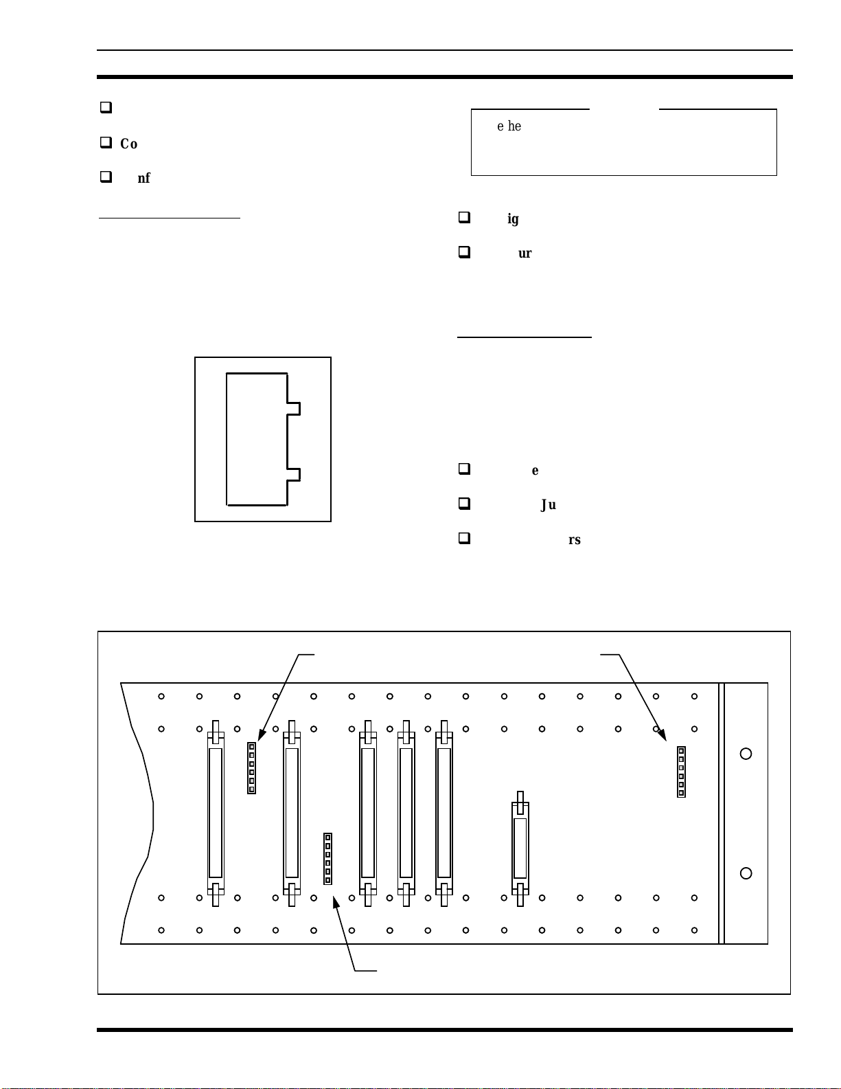
STEP 2 - BACKPLANE CONFIGURATION
One Channel Per Shelf
For Simulcast systems with up to 17 sites using one
channel per shelf, configure jumpers on the Digital shelf’s
Backplane Panel (ROA 117 2222). Refer to Table 2 and
install or remove jumpers on J6, J7, and J8 as required.
Location of headers is shown in Figure 3 and on Installation
Diagram 193D1054, sheet 2.
q
q
Configure Jumpers on Backplane J6.
q
q
Configure Jumpers on Backplane J7.
q
q
Remove Jumpers From Backplane J8.
87
65
43
21
Figure 2 - ROA 117 2227 Header Pinouts
J7
J6
J8
J5 J10 J1J4
J3
1
1
1
J9
J6
J7J8
Figure 3 - Backplane Jumper Locations
NOTE
LBI-39153 COMPACT VERTICAL VOTER CONFIGURATION
12
Two Channels Per Shelf
For Simulcast systems with up to 6 sites using two
channels per shelf, configure jumpers on the Digital shelf’s
Backplane Panel (ROA 117 2222). Refer to Table 4 and
install or remove jumpers on J6, J7, and J8 as required.
Location of headers is shown in Figure 3 and Installation
Diagram 193D1054, sheet 2.
q
q
Remove Jumpers from Backplane J6.
q
q
Configure Jumpers on Backplane J7.
q
q
Configure Jumpers on Backplane J8.
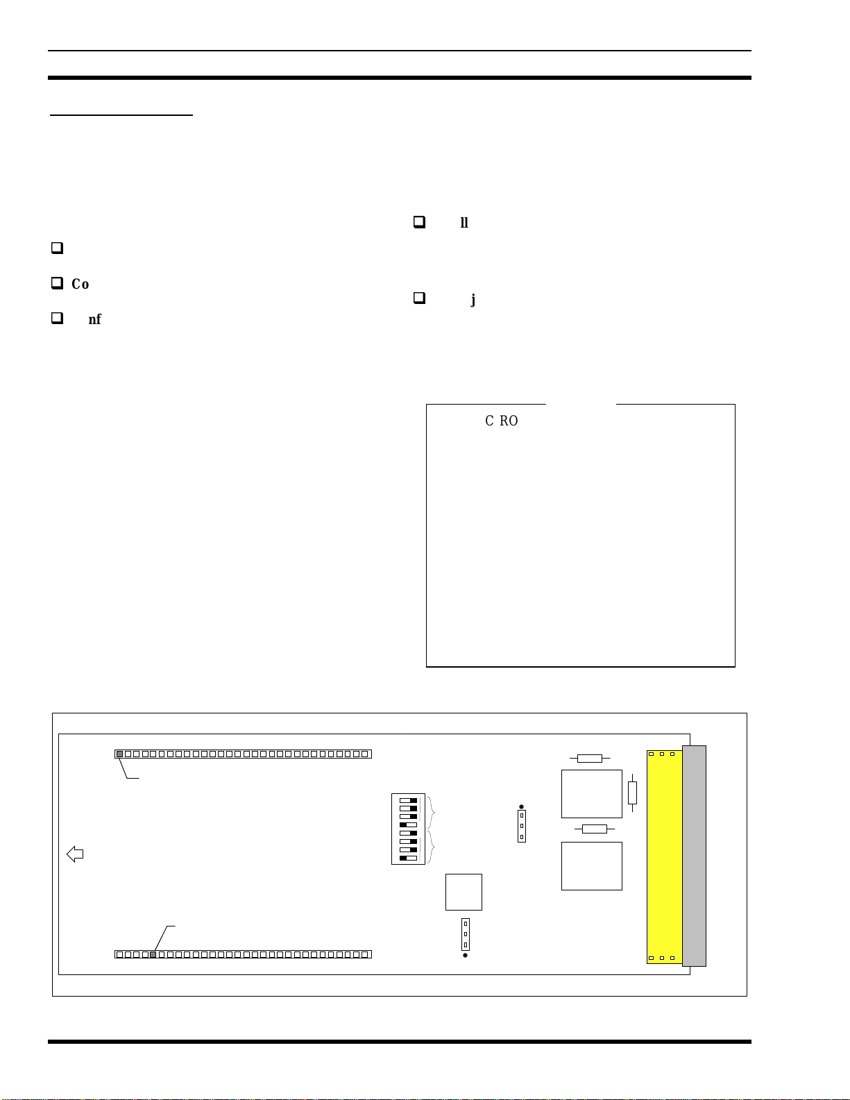
STEP 3 - ROCKWELL MODEM
INTERFACE CARD CONFIGURATION
Configure the jumpers X6 and X7 on the RMIC
according to the following criteria (refer to Figure 4 for
connector locations):
q
q
Install jumper X6 on connector X4 pins 1 and 2.
This connects a 600 Ohm resistor across the
Receive phone lines.
q
q
Install jumper X7 on connector X3 pins 2 and 3.
Modem sends the CTS signal to the microcomputer
only after the microcomputer sends an RTS signal
and the RM is ready.
NOTE
On RMIC ROA 117 2247/1 Rev. R1 runs are cut
and additional jumpers are installed to allow the
RMIC to transmit in the RM mode and receive RS-
232 data. This configuration is only used in
Simulcast systems with Digital Dispatch (i.e. there
is an IMC and system uses DV, Aegis, or Digital
Data).
The Modification Instructions 350A1692 detail the
steps necessary to isolate T1 from the circuit and
disconnect MRXD from the RX_DATA line. It
also provides instructions for installing the zero
ohm jumpers R43 and R44.
Refer to LBI-39152 for additional details.
X5
X4
1
1
X3
CBA
32
CBA
1
R44
T2
U5
T1
R43
30
31
Front
Key Plug
1
61
X1
X2
Pin not used S1
R45
1
2
3
4
5
6
7
8RX
Level
TX
Level
Figure 4 - RMIC Jumper Locations
NOTE

COMPACT VERTICAL VOTER CONFIGURATION LBI-39153
13
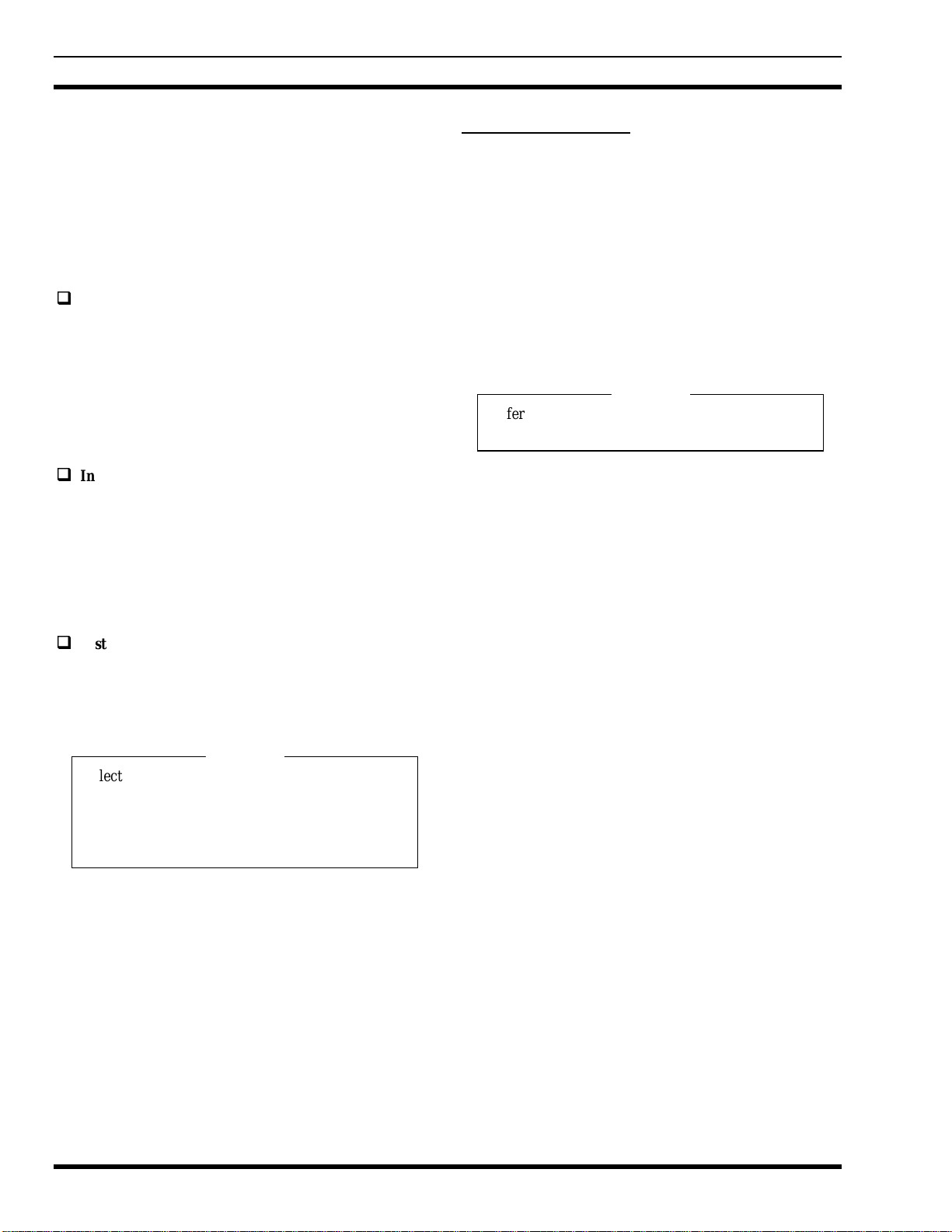
STEP 4 - DIGITAL RECEIVER
CONFIGURATION
Use the following procedure to configure each Voter
Digital Receiver:
q
q
Set DIP Switches S1, S2, and S3:
Each Digital Receiver in a Voter channel is identified as
a Digital Receiver and is assigned a time slot number. The
time slot number is used to control the sequencing of
messages between the Digital Receivers and the Selector.
1. Set the Digital Receiver's DIP switches to the
following positions, refer to Figure 5:
•• SWITCH S1
Sections 1-6: Set the time slot number.
Refer to Table 5 for the switch settings of each
time slot number.
Sections 7-8: Closed, not used.
•• SWITCH S2
Sections 1-8: Closed, not used.
•• SWITCH S3
Sections 1-6: Closed, not used.
Section 7: Closed, placing the unit in the
Digital Receiver mode.
Section 8: Closed, not used.
q
q
Install Digital Receiver Configuration Plug
1. Install the Digital Receiver Configuration Plug
(ROA 117 2242) into connector X2 on the Digital
Receiver card.
2. Ensure the configuration plug is properly oriented.
The top of the plug will read "Digital Receiver".
3. Ensure pin 1 of the Configuration Plug (identified
by square solder pad) plugs into X2 pin 1.
q
q
Install Flash Loader PROM
1. Ensure the Flash Loader PROM (RON 107 756) is
installed in socket XU26.
The label on the top of the PROM indicates the
PROM is programmed with the flash loading
software "FLASHBURN" and the PROM revision.
No revision indicates the original release.
q
q
Install Digital Receiver Into Digital Voter Shelf
1. Insert the Digital Receiver into its designated slot.
Refer to the Card Configuration Guide.
NOTE
Digital Receivers cards can be plugged and
unplugged from the voter shelf at will with power
applied. However care should be exercised when
using the extender card since the long ground pins
are only on the cards.
STEP 5 - SELECTOR CONFIGURATION
Use the following procedure to configure the Voter
Selector, refer to Figure 5:
q
q
Set DIP Switches S1, S2, and S3:
1. Set the Selector's DIP switches to the following
positions:
•• SWITCH S1
Sections 1-8: Closed, not used.
12345678
S1
12345678
S2
12345678
S3
S1-1 thru 6 = Time Slot Number
OPEN OPEN OPEN
1
144
442
244
443
3
S3-7 = Configuration.
Figure 5 - DIP Switches S1 thru S3
Table 5 - Digital Receiver Time Slot Settings
Slo
t
#DIP Switch 1 Section
123456
1OCCCCC
2COCCCC
3OOCCCC
4CCOCCC
5OCOCCC
6COOCCC
7OOOCCC
8CCCOCC
9OCCOCC
10 COCOCC
11 OOCOCC
12 CCOOCC
13 OCOOCC
14 COOOCC
15 OOOOCC
16 CCCCOC
17 OCCCOC
18 COCCOC
NOTE
LBI-39153 COMPACT VERTICAL VOTER CONFIGURATION
14
•• SWITCH S2
Sections 1-8: Closed, not used.
•• SWITCH S3
Sections 1-6: Closed, not used.
Section 7: Open, placing the unit in the
Selector mode.
Sections 8: Closed, not used.
q
q
Install Configuration Plug
1. Install the Selector Configuration Plug (ROA 117
2241) into connector X2 on the Selector's GPTC.
2. Ensure the configuration plug is properly oriented.
The top of the plug will read "Selector".
3. Ensure pin 1 of the Configuration Plug (identified
by square solder pad) plugs into X2 pin 1.
q
q
Install Flash Loader PROM
1. Ensure the Flash Loader PROM (RON 107 756) is
installed in socket XU26.
The label on the top of the PROM indicates the
PROM is programmed with the flash loading
software "FLASHBURN" and the PROM revision.
No revision indicates original release.
q
q
Install Selector Into Digital Voter Shelf
1. Insert the Selector into its designated slot. Refer to
the Card Configuration Table for the correct
position.
NOTE
Selectors cards can be plugged and unplugged from
the voter shelf at will with power applied.
However care should be exercised when using the
extender card since the long ground pins are only
on the cards.
3. Reset the module by pressing S4.
STEP 6 - VOTER SOFTWARE
INSTALLATION
This procedure provides instructions for downloading
the Voter software. The Voter software is included in the
Voter Media Kit, 350A1521G1. The installation process
involves using an IBM compatible personal computer (PC),
and interconnecting programming cable (19B804346P111)
to download Voter software to the Digital Receivers and
Selectors.
Equipment Required
•IBM PC/XT/AT or compatible with at least 640K
memory, monitor and keyboard running MS-DOS
version 3.0 or higher.
•Hard disk is recommended; but, not required.
•Serial Port configured as COM1.
•Programming Cable 19B804346P111.
•Software Media Kit 350A1521G1 (or later), refer
to SRN for software compatibility.
NOTE
Refer to Software Release Notes to verify software
requirements and hardware compatibility.
PC Setup
During first time use it may be necessary to setup the
PC. The loadable Voter software must reside on the PC or
floppy disk as an Intel Hex file. The "leafoff.exe" file is the
executable program which loads the Voter hex file into the
Digital Receiver or Selector. Both files should be in the
same directory.
Prepare the PC for programming the Voter Digital
Receiver and Selector GPTC boards by performing the
following steps:
1. Using standard DOS commands or a software file
manager, create a directory named "VOTER" on
the PC's hard drive (directory name is user
selectable). This step is only required for first time
use. When upgrading, all existing files should be
archived before copying the new files into the
directory.
2. Make "VOTER " the current directory and copy
the following files from the software distribution
diskette into the "VOTER " directory:
•leafoff.exe
•hexfile.hex
Programming the Voter
1. Connect the 19B804346P111 programming cable
from the PC's Comm Port 1 to the RJ-12 phone
jack "PROG" on the front of the Digital Receiver
or Selector.
NOTE
NOTE

COMPACT VERTICAL VOTER CONFIGURATION LBI-39153
15
NOTE
Power must be applied to the Digital Voter when
programming the Digital Receiver or Selector.
2. From the "VOTER" directory, run the leafoff.exe
program by entering the command:
"
leafoff
hexfile
.hex-1".
Replace "hexfile" with the Voter software file
name.
3. The program will reset the Digital Receiver or
Selector and run the Flash Loader program. The
program erases the existing Voter software residing
in the Flash PROM U25 and writes the new Voter
software into the Flash PROM.
When the program is finished, the PC will display
the message "Radio Programmed. Closing down
port COM1." Wait a couple of seconds before
disconnecting the programming cable from the
"PROG" connector. This allows time for the PC
to reset the Digital Receiver or Selector and
initialize the Voter application program loaded in
the Flash PROM.
4. Repeat Steps 2 and 3 to program additional Digital
Receivers or Selectors.
NOTE
To save time, it is possible to set up a batch file to
run the Flash loading program. The following is an
example batch file.
Name the batch, for example, FL.BAT. Names in
italics, such as "voter" is the name of the directory
where the hexfile and leafoff reside. The file
named "hexfile" is the file to be loaded and
"leafoff" is the executable program. Enter the
following batch program:
cd\
voter
leafoff
hexfile
.hex-1
The batch file performs the operations outlined in
Step 2. To run the program, type "FL" <enter> to
program the Digital Receiver or Selector.
If any difficulty is encountered when loading the
program, refer to the Troubleshooting section in this manual.
Check out the Digital Receiver and Selector operation.
If any problems are encountered, refer to the troubleshooting
procedures in this manual and LBI-39151.
POST CONFIGURATION CHECKS
1. Check Main Site GETC and Satellite Site Receivers for
proper configuration.
2. Check Backplane for proper installation of jumpers on
J6, J7 and J8.
3. Check EDACS Interface Panels for proper installation
of the jumpers on J30, J31, J40 and J41.
4. Check all Digital Receivers and Selectors for the correct
Configuration Plug and DIP switch settings.
5. Check all RMICs for proper installation of jumpers on
X3 and X4 and line level switch settings.
6. If Simulcast Digital Dispatch, ensure modified RMIC(s)
is installed in slot 2 and slot 12 (if 2-channel).
7. Ensure all modules are installed in their proper slots
according to the Card Configuration Table.
NOTE
NOTE

LBI-39153 CARD CONFIGURATION GUIDE (350A1612)
16
CARD CONFIGURATION GUIDE
(350A1612)
The Card Configuration Guide (350A1612) provides
instructions for installing modules in the CV2Analog and
Digital Voter Shelves.
NOTE
The coded information presented will help field
service personnel determine the proper card
configuration for their particular application.
These codes are generated by Ericsson's CAT
(CATalog Orders Program) when initially
configuring a customer's system. However, they
are included for reference only and should not be
used to requisition equipment.
The CAT provides three 15-digit code words to define
the configuration. The first 3 digits identify the code word
as VP1, VP2, and VP3. Remaining digits convey
information as shown in Tables 6, 8, and 9. Characters A to
Z indicate numerical values from 1 to 26 as shown in Table
7.
Racks, power supplies, shelves and harnesses are
provided and assembled for the total number of sites and
expansion sites. Plug-in cards are not provided for
expansion sites.
NOTE
1. Voted (Non-Simulcast) systems cannot mix
RM and RS-232 connected satellite sites. The
Main Site can be RM or RS-232 no matter how
satellite sites are connected.
2. If system is Simulcast with Digital Dispatch,
the RM in slots 2 and 12 must be configured
for RS-232 receive. For RMIC ROA 117
2247/1 (Rev. R1 and R2 only) the RMIC is
modified according to the RMIC Modification
Instructions 350A1692 (part of Mod Kit
350A1693). Refer to LBI-39152 for
modification details.
3. All channels are identical.
4. If the system uses two channels per shelf and
the number of channels (VP1-10) is odd, the
right half of the last shelf is not populated.
USING THE SLOT CONFIGURATION
TABLES
Use the following guidelines for Simulcast or Voted
(Non-Simulcast) to determine which chart is applicable.
Simulcast Systems (VP1-5 = S)
1. Determine whether each Digital shelf is to be
configured for 1 channel per shelf or 2 channels per
shelf.
• If the sum of VP1-6, VP1-7, VP1-8, and VP1-
9 is greater than 6, configure for 1 channel per
shelf.
• If the sum of VP1-6, VP1-7, VP1-8, and VP1-
9 is 6 or less, configure for 2 channels per
shelf.
2. Determine the number of Auxiliary Sites (VP1-8).
3. Determine the number of sites (VP1-6).
Configure per the appropriate chart. Observe the notes
for that chart.
Voted Systems (VP1-5 = V)
1. Determine whether each Digital shelf is to be
configured for 1 channel per shelf or 2 channels per
shelf.
• If the sum of VP1-6, VP1-7, VP1-8, and VP1-
9 is greater than 6, configure for 1 channel per
shelf.
• If the sum of VP1-6, VP1-7, VP1-8, and VP1-
9 is 6 or less, configure for 2 channels per
shelf.
2. Determine how Satellite Sites are connected.
• If VP2-4, VP2-5, etc. is "R," connection is
RS232.
• If VP2-4, VP2-5, etc. is "M," connection is
Rockwell Modem (RM).
• All satellite sites should be connected the same
way.
3. Determine the number of sites (VP1-6).
Configure per the appropriate table. Observe the notes
for that table.
NOTE
NOTE

CARD CONFIGURATION GUIDE (350A1612) LBI-39153
17
Table 6 - Information in VP1
DIGIT VALUE MEANING
4
G
E
A
GE label
Ericsson label
ETS label
5S
V
Simulcast
Voted (non-simulcast)
6 A-J Number of sites.
7 A-J,0 Number of expansion sites.
8 A-P,0 Number of Auxiliary Receiver sites.
9 A-P,0 Number of expansion Auxiliary
Receiver sites.
10 B-X Number of Channels.
11 R
M
Main Site data is RS232 (no data to
switch).
Main Site & Switch data is RM (for
Digital Dispatch).
12
R
M
N
Switch data is RM (for VDI).
Main Site data is RS232 (from
selector).
Switch data is RM (for VDI).
Main Site data is RM (from
Selector).
No VDI
13 8
R
Install in 83 inch cabinet
Install in 86 inch open rack
14
1
2
D
Equip with 120V power supplies
Equip with 240V power supplies
DC, not equipped with standard
supplies
15 A-L Total number of cabinets or racks
Note: Digit 11 affects slot 2. Digit 12 affects slot 4.
Table 8 - Information in VP2
DIGIT VALUE MEANING
4R
M
N
Aux Site 1 connected RS232
Aux Site 1 connected RM
Aux Site 1 not equipped
5R
M
N
Aux Site 2 connected RS232
Aux Site 2 connected RM
Aux Site 2 not equipped
6R
M
N
Aux Site 3 connected RS232
Aux Site 3 connected RM
Aux Site 3 not equipped
7R
M
N
Aux Site 4 connected RS232
Aux Site 4 connected RM
Aux Site 4 not equipped
8R
M
N
Aux Site 5 connected RS232
Aux Site 5 connected RM
Aux Site 5 not equipped
9R
M
N
Aux Site 6 connected RS232
Aux Site 6 connected RM
Aux Site 6 not equipped
10 R
M
N
Aux Site 7 connected RS232
Aux Site 7 connected RM
Aux Site 7 not equipped
11 R
M
N
Aux Site 8 connected RS232
Aux Site 8 connected RM
Aux Site 8 not equipped
12 R
NAux Site 9 connected RS232
Aux Site 9 not equipped
13 R
NAux Site 10 connected RS232
Aux Site 10 not equipped
14 X Not used
15 X Not used
Table 7 - Number values for letters for VP1-6, 7, 8, 10, & 15
LETTER NUMBER LETTER NUMBER LETTER NUMBER
A1J10S19
B2K11T20
C3L12U21
D4M13V22
E5N14W23
F6O15X24
G7P16Y25
H8Q17Z26
I 9 R 18 0 (zero) 0

LBI-39153 CARD CONFIGURATION GUIDE (350A1612)
18
Table 9 - Information in VP3
DIGIT VALUE MEANING
4R
NAux Site 11 connected RS232
Aux Site 11 not equipped
5R
N
Aux Site 12 connected RS232
Aux Site 12 not equipped
6R
NAux Site 13 connected RS232
Aux Site 13 not equipped
7R
NAux Site 14 connected RS232
Aux Site 14 not equipped
8R
NAux Site 15 connected RS232
Aux Site 15 not equipped
9R
NAux Site 16 connected RS232
Aux Site 16 not equipped
10 X Not used
11 X Not used
12 X Not used
13 X Not used
14 X Not used
15 X Not used
Note: Aux site refers to non-transmit sites in Simulcast
and to satellite sites in Voted systems. Simulcast systems
can have a maximum of 3 Rockwell Modem connected Aux
sites in one channel per shelf configurations. Voted systems
can have one RM connected main site and a maximum of 8
Rockwell Modem connected satellite sites or a maximum of
16 RS232 connected satellite sites.
CONFIGURATION TABLES
Digital Voter shelves are configured according to the
following Configuration Tables.
• Table 10 - Digital Voter Configuration, Simulcast,
2 to 6 RS232 Sites, 2 Channels/Shelf, no RM Sites
• Table 11 - Analog Voter Configuration, Simulcast,
2 to 6 RS232 Sites, no RM Sites
• Table 12 - Digital Voter Configuration, Simulcast,
2 to 5 RS232 Sites, 2 channels/shelf, One RM Site
• Table 13 - Analog Voter Configuration, Simulcast,
2 to 5 RS232 Sites, One RM Site
• Table 14 - Digital Voter Configuration, Simulcast,
1 channel/shelf, 2 to 12 RS232 Sites and no RM
Sites
• Table 15 - Analog Voter Configuration, Simulcast,
2 to 12 RS232 Sites and no RM Sites
• Table 16 - Digital Voter Configuration, Simulcast,
1 channel/shelf, 13 to 17 RS232 Sites and no RM
Sites
• Table 17 - Analog Voter Configuration, Simulcast,
13 to 17 RS232 Sites and no RM Sites
• Table 18 - Digital Voter Configuration, Simulcast,
1 channel/shelf, 2 to 11 RS232 Sites and One RM
Site
• Table 19 - Analog Voter Configuration, Simulcast,
2 to 11 RS232 Sites and One RM Site
• Table 20 - Digital Voter Configuration, Simulcast,
1 channel/shelf, 12 to 15 RS232 Sites and One RM
Site
• Table 21 - Analog Voter Configuration, Simulcast,
12 to 15 RS232 Sites and One RM Site
• Table 22 - Digital Voter Configuration, Simulcast,
1 channel/shelf, 2 to 10 RS232 Sites and Two RM
Sites
• Table 23 - Analog Voter Configuration, Simulcast,
2 to 10 RS232 Sites and Two RM Sites
• Table 24 - Digital Voter Configuration, Simulcast,
1 channel/shelf, 11 to 13 RS232 Sites and Two RM
Sites
• Table 25 - Analog Voter Configuration, Simulcast,
11 to 13 RS232 Sites and Two RM Sites
• Table 26 - Digital Voter Configuration, Simulcast,
1 channel/shelf, 2 to 9 RS232 Sites and Three RM
Sites
• Table 27 - Analog Voter Configuration, Simulcast,
2 to 9 RS232 Sites and Three RM Sites
• Table 28 - Digital Voter Configuration, Simulcast,
1 channel/shelf, 10 or 11 RS232 Sites and Three
RM Sites
• Table 29 - Analog Voter Configuration, Simulcast,
10 or 11 RS232 Sites and Three RM Sites
• Table 30 - Voted, 2 Channel, RM Connected
• Table 31 - Voted, 1 Channel, RM Connected
• Table 32 - Voted, 2 Channel, RS232 Connected
• Table 33 - Voted, 1 Channel, RS232 Connected
Table 10 - Digital Voter Configuration, Simulcast, 2 to 6 RS232 Sites, 2 Channels/Shelf, no RM Sites
RS-232
sites slot 1 slot 2 slot 3 slot 4 slot 5 slot 6 slot 7 slot 8 slot 9 slot 10 slot 11 slot 12 slot 13 slot 14 slot 15 slot 16 slot 17 slot 18 slot 19 slot 20
2 SEL RM DR1 DR2 SEL RM DR1 DR2
3 SEL RM DR1 DR2 DR3 SEL RM DR1 DR2 DR3
4 SEL RM DR1 DR2 DR3 DR4 SEL RM DR1 DR2 DR3 DR4
5 SEL RM DR1 DR2 DR3 DR4 DR5 SEL RM DR1 DR2 DR3 DR4 DR5
6 SEL RM DR1 DR2 DR3 DR4 DR5 DR6 RS232 SEL RM DR1 DR2 DR3 DR4 DR5 DR6 RS232
Slots 2 and 12 are RS232 if main site is connected RS232 (no switch or no Digital Dispatch).
If VDI, slots 4 and 14 are RS232.
Table 11 - Analog Voter Configuration, Simulcast, 2 to 6 RS232 Sites, no RM Sites
SHELF SLOT 1 SLOT 2 SLOT 3 SLOT 4 SLOT 5 SLOT 6 AUDIO SLOT P.S. SLOT
TOP A.V. R CH. SITE 1 R CH. SITE 2 R CH. SITE 3 R CH. SITE 4 R CH. SITE 5 R CH. SITE 6 AUDIO P.S.
D.V.
BOT A.V. L CH. SITE 1 L CH. SITE 2 L CH. SITE 3 L CH. SITE 4 L CH. SITE 5 L CH. SITE 6 AUDIO P.S.
Key:
RM Rockwell Modem Interface Card (RMIC) ROA 117 2247/1
DR1 Digital Receiver One ROA 117 2240/1
RS232 RS232 Interface Card ROA 117 2247/2
SEL Selector ROA 117 2240/2
Notes:
1 Digital Dispatch implies an IMC switch and Digital Voice or Data. A site may be connected RS232 even with IMC switch if system has no Digital Voice or Data.
2. Install a Receiver module (19D903175G1) in each Analog Voter slot which has a corresponding Digital Receiver called out in the Digital Voter shelf.
3. Install an Analog Voter Audio Module (19D413958G5) wherever AUDIO is called out in the Audio Slot.
4. Install a Power Supply Module (19D413917G4) in all Analog Voter shelves.

Table 12 - Digital Voter Configuration, Simulcast, 2 to 5 RS232 Sites, 2 channels/shelf, One RM Site
RS232
sites slot 1 slot 2 slot 3 slot 4 slot 5 slot 6 slot 7 slot 8 slot 9 slot 10 slot 11 slot 12 slot 13 slot 14 slot 15 slot 16 slot 17 slot 18 slot 19 slot 20
2 SEL RM DR1 DR2 DR6 RM SEL RM DR1 DR2 DR6 RM
3 SEL RM DR1 DR2 DR3 DR6 RM SEL RM DR1 DR2 DR3 DR6 RM
4 SEL RM DR1 DR2 DR3 DR4 DR6 RM SEL RM DR1 DR2 DR3 DR4 DR6 RM
5 SEL RM DR1 DR2 DR3 DR4 DR5 DR6 RM SEL RM DR1 DR2 DR3 DR4 DR5 DR6 RM
Slots 2 and 12 are RS232 if main site is connected RS232 (no switch or no digital dispatch).
If VDI, slots 4 and 14 are RS232.
Table 13 - Analog Voter Configuration, Simulcast, 2 to 5 RS232 Sites, One RM Site
SHELF SLOT 1 SLOT 2 SLOT 3 SLOT 4 SLOT 5 SLOT 6 AUDIO SLOT P.S. SLOT
TOP A.V. R CH. SITE 1 R CH. SITE 2 R CH. SITE 3 R CH. SITE 4 R CH. SITE 5 R CH. SITE 6 AUDIO P.S.
D.V.
BOT A.V. L CH. SITE 1 L CH. SITE 2 L CH. SITE 3 L CH. SITE 4 L CH. SITE 5 L CH. SITE 6 AUDIO P.S.
Note:
In Simulcast systems with RM connected sites (usually Aux sites), some Analog Voter slots will be empty. Ex. If two RS232 sites and one RM
site, only slots 1, 2, and 6 have Receiver Modules.
Table of contents


