manuals.online logo
Brands
  1. Home
  2. •
  3. Brands
  4. •
  5. Ericsson
  6. •
  7. Radio
  8. •
  9. Ericsson 2219 User manual

Ericsson 2219 User manual


Install RadioInstall Radio
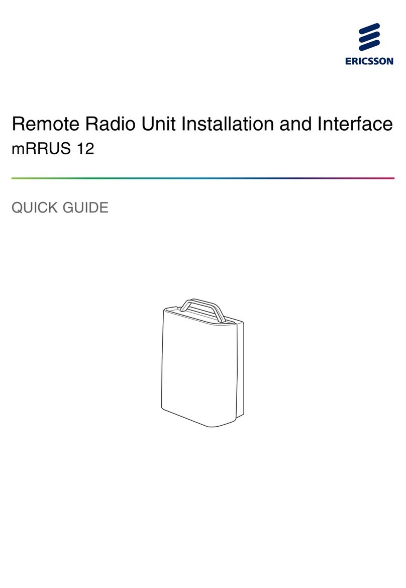
Radio 2219Radio 2219
Installation Instructions
Ge11067AGe11067A
67/1531-LZA 701 6001/1 Uen J67/1531-LZA 701 6001/1 Uen J

CopyrightCopyright
© Ericsson AB 2016, 2017. All rights reserved. No part of this document may© Ericsson AB 2016, 2017. All rights reserved. No part of this document may
be reproduced in any form without the be reproduced in any form without the written permission of the copyrightwritten permission of the copyright
owner.owner.
DisclaimerDisclaimer
The contents of this document are subject to revision without notice due toThe contents of this document are subject to revision without notice due to
continued progress in continued progress in methodologymethodology, design and , design and manufacturing. Ericsson shallmanufacturing. Ericsson shall
have no liability for any error or have no liability for any error or damage of any kind resulting from the use ofdamage of any kind resulting from the use of
this document.this document.
Trademark ListTrademark List
All trademarks mAll trademarks mentioned hereentioned herein are the propin are the property of their respectierty of their respective owners.ve owners.
These are shown in the These are shown in the documentdocument Trademark InformationTrademark Information..
67
67/1/153531-1-LZLZA A 70701 61 600001/1/1 U1 Uen en JJ||20201717-0-06-6-0606

ContentsContents
11 IntroductionIntroduction 11
1.11.1 DocumentationDocumentation 11
1.21.2 ToolsTools 11
1.31.3 ConditionsConditions 22
22 Work ProcessWork Process 44
33 Unpack and Check MaterialsUnpack and Check Materials 55
44 Installation AlternativesInstallation Alternatives 77
4.14.1 Mounting Direction Mounting Direction AlternativesAlternatives 88
55 Prepare for InstallationPrepare for Installation 1010
5.15.1 Install Mounting BracketInstall Mounting Bracket 1010
5.25.2 Preassemble Single Pole Clamp and Prepare RadioPreassemble Single Pole Clamp and Prepare Radio
(Optional)(Optional) 1111
5.35.3 Install SFP ModuleInstall SFP Module 1212
5.45.4 Assemble DC Assemble DC Power ConnePower Connectorctor 1414
66 Install RadioInstall Radio 1515
6.16.1 Install Multiple RadiosInstall Multiple Radios 1515
6.26.2 Assemble SinAssemble Single Pole Clamgle Pole Clamp (Optional)p (Optional) 1515
6.36.3 Hoist RadioHoist Radio 1616
6.46.4 Attach Radio to RAttach Radio to Railail 1717
6.56.5 Attach Radio to SAttach Radio to Single Pole Clingle Pole Clamp (Optional)amp (Optional) 1818
6.66.6 Connect CablesConnect Cables 1919
6.76.7 Optional ActionsOptional Actions 2626
77 VeVerify Radio Installation on rify Radio Installation on SiteSite 2828
7.17.1 Check SiteCheck Site 2828
7.27.2 Power Up RadioPower Up Radio 3131
7.37.3 Check Radio After Power UpCheck Radio After Power Up 3131
88 Perform Concluding RoutinesPerform Concluding Routines 3333
99 ReferencesReferences 3434
Contents
Contents
67/67/15153131-L-LZA ZA 70701 61 600001/1/1 1 UeUen n JJ||20201717-0-06-6-0606

Install Radio
Install Radio
6767/1/153531-1-LZLZA 7A 701 01 60600101/1 /1 UeUen n JJ||20201717-0-06-6-0606

11 IInnttrroodduuccttiioonn
This document describes how to install Radio 2219 on site.This document describes how to install Radio 2219 on site.
11..11 DDooccuummeennttaattiioonn
Make sure that the Make sure that the followingfollowing
documents are read and understood:documents are read and understood:
•• Personal Health and SafetyPersonal Health and Safety
InformationInformation
•• System Safety InformationSystem Safety Information
11..22 TToooollss
Table 1
Table 1lists the lists the required tools for installing the radio.required tools for installing the radio.
TTable able 1 1 TTools ools RequiredRequired
Product NameProduct Name
Electrostatic Discharge (ESD) wrist strap (staticElectrostatic Discharge (ESD) wrist strap (static
control wrist strap)control wrist strap)
Torque wrench 0.5–4 Nm, TORX® T20Torque wrench 0.5–4 Nm, TORX® T20
Torque wrench 5–25 Nm, TORX® T30Torque wrench 5–25 Nm, TORX® T30
Introduction
Introduction
67/67/15153131-L-LZA ZA 70701 61 600001/1/1 1 UeUen n JJ||20201717-0-06-6-0606 11

Product NameProduct Name
Torque wrench 5–25 Nm, socket 10 mmTorque wrench 5–25 Nm, socket 10 mm
Torque wrench 5–25 Nm, socket 13 mmTorque wrench 5–25 Nm, socket 13 mm
Torque wrench 5–25 Nm, open-ended head 20 mmTorque wrench 5–25 Nm, open-ended head 20 mm
Torque wrench 5 Nm, open-ended head 22 mmTorque wrench 5 Nm, open-ended head 22 mm
Lifting deviceLifting device
11..33 CCoonnddiittiioonnss
The conditions in this section must The conditions in this section must be fulfilled before work starts.be fulfilled before work starts.
11..33..11 BBeeffoorre e GGooiinng g tto o tthhe e SSiittee
Before going to site, make sure of the following:Before going to site, make sure of the following:
•• Site access permission has been Site access permission has been received.received.
•• DocumentatiDocumentation stated on stated inin Documentation
Documentationon page 1 is available.on page 1 is available.
•• All applicaAll applicable tools stated inble tools stated in Table 1
Table 1are available.are available.
11..33..22 BBeeffoorre e SSttaarrttiinng g tthhe e IInnssttaallllaattiioonn
Before starting the installation, make sure of Before starting the installation, make sure of the following:the following:
•• The site is prepared according to the .The site is prepared according to the .
•• The ordered hardware is available.The ordered hardware is available.
Install Radio
Install Radio
2267/67/15153131-L-LZA ZA 70701 61 600001/1/1 1 UeUen n JJ||20201717-0-06-6-0606

•• The rail is installed on the site. For more information on how to install theThe rail is installed on the site. For more information on how to install the
rail, refer torail, refer to Install RailInstall Rail..
•• The power supply for the radio is installed and tested at the radio site.The power supply for the radio is installed and tested at the radio site.
•• The site grounding system is installed and tested.The site grounding system is installed and tested.
•• Either of the Either of the following alternatifollowing alternatives must be ves must be installed and tested:installed and tested:
–– A main switch anA main switch and an external fusd an external fusee
–– A circuit breakerA circuit breaker
Introduction
Introduction
67/67/15153131-L-LZA ZA 70701 61 600001/1/1 1 UeUen n JJ||20201717-0-06-6-0606 33

22 WWoorrk k PPrroocceessss
Figure 1
Figure 1shows the work process for installing the radio.shows the work process for installing the radio.
Ge11051AGe11051A
Unpack and CheckUnpack and Check
MaterialsMaterials
Install Mounting BracketInstall Mounting Bracket
Verify RadioVerify Radio
InstallationInstallation
Power Up RadioPower Up Radio
Check RadioCheck Radio
After PAfter Power Upower Up
Perform ConcludingPerform Concluding
RoutinesRoutines
Install RadioInstall Radio
WWaalll l IInnssttaallllaattiioonnPPoolle e IInnssttaallllaattiioonn
Figure Figure 1 1 Radio Radio InstallatInstallation ion Work Work ProcessProcess
Install RadioInstall Radio
4467/67/15153131-L-LZA ZA 70701 61 600001/1/1 1 UeUen n JJ||20201717-0-06-6-0606

33 UUnnppaacck k aannd d CChheecck k MMaatteerriiaallss
The radio is transported in a The radio is transported in a corrugated box.corrugated box.
Note:Note: The radio must not be stored in an outdoor environment, even if it isThe radio must not be stored in an outdoor environment, even if it is
kept in its kept in its original packagingoriginal packaging. The packed radio can . The packed radio can only be keptonly be kept
outdoors during installationoutdoors during installation. After . After installationinstallation, it , it must be powered upmust be powered up
within 48 hours even if it is not within 48 hours even if it is not taken into service. The reason is totaken into service. The reason is to
protect the internal units from protect the internal units from local climate conditions.local climate conditions.
Do not dispose of the packaging as it can be required to return faultyDo not dispose of the packaging as it can be required to return faulty
equipment. For more information about handling faulty equipment, refer toequipment. For more information about handling faulty equipment, refer to
Handling Faulty EquipmentHandling Faulty Equipment..
StepsSteps
To unpack and check the materials:To unpack and check the materials:
1.1.
Ge8583A
Ge8583A
Examine the packaging forExamine the packaging for
damage. If it is damaged,damage. If it is damaged,
immediately register a immediately register a complaintcomplaint
with the transport company. It iswith the transport company. It is
recommenderecommended that a d that a photo of thephoto of the
damages be taken to improve thedamages be taken to improve the
claims process.claims process.
2.2.
Ge8584A
Ge8584A
Remove the straps from theRemove the straps from the
corrugated box.corrugated box.
Unpack and Check Materials
67/67/15153131-L-LZA ZA 70701 61 600001/1/1 1 UeUen n JJ||20201717-0-06-6-0606 55

3.3.
Ge6679C
Ge6679C
Remove the tape from theRemove the tape from the
corrugated box.corrugated box.
Note:Note:
Make sure that the items in theMake sure that the items in the
corrugated box are not damaged.corrugated box are not damaged.
4.4. Check that the items deliveredCheck that the items delivered
correspond to the packing list.correspond to the packing list.
5.5.
Ge8585A
Ge8585A
Remove the fitments.Remove the fitments.
6.6.
Ge11052AGe11052A
Remove the radio from the box,Remove the radio from the box,
and carefully place the radio onand carefully place the radio on
the ground on a clean, softthe ground on a clean, soft
surface, or on the surface, or on the packagingpackaging
material.material.
Note:Note:
Make sure to keep the radioMake sure to keep the radio
clean from moisture and dirt.clean from moisture and dirt.
Install Radio
Install Radio
6667/67/15153131-L-LZA ZA 70701 61 600001/1/1 1 UeUen n JJ||20201717-0-06-6-0606

44 IInnssttaallllaattiioon n AAlltteerrnnaattiivveess
Ge11043A
Ge11043A
CC
BB
AA
DD
Figure Figure 2 2 Installation Installation Alternatives Alternatives 1 1 (2)(2)
Installation AlternativesInstallation Alternatives
67/67/15153131-L-LZA ZA 70701 61 600001/1/1 1 UeUen n JJ||20201717-0-06-6-0606 77

G
G
EEFF
Ge12493CGe12493C
Figure Figure 3 3 Installation Installation Alternatives Alternatives 2 2 (2)(2)
TTable able 2 2 Key Key to to InstallatInstallation ion AlternatAlternativesives
IInnssttaallllaattiioon n MMeetthhoodd DDeessccrriippttiioonn
AA Wall iWall installationnstallation
BB PPoolle e iinnssttaallllaattiioonn
CC PPoolle e iinnssttaallllaattiioon n wwiitth h ssiinngglle e ppoollee
clampclamp
DD PPoolle e iinnssttaallllaattiioon n wwiitth h aaddaappttoor r ppllaattee(1)(1)
EE RRaaddiio o MMoouunntteed d BBeehhiinnd d tthhee
AntennaAntenna(2)(2)
FF, , GG RRaaddiio o MMoouunntteed d BBeelloow w tthhe e AAnntteennnnaa
(1)(1) TTo install the radio using adaptor plate, refer to Mounting Description RRU Adaptor Plate.o install the radio using adaptor plate, refer to Mounting Description RRU Adaptor Plate.
(2)(2) For more information, refer to Install Radio Mounted Behind the Antenna.For more information, refer to Install Radio Mounted Behind the Antenna.
44..11 MMoouunnttiinng g DDiirreeccttiioon n AAlltteerrnnaattiivveess
Figure 4
Figure 4andand Table 3Table 3describe where to install tdescribe where to install the mounting bracket on thehe mounting bracket on the
radio, based on radio, based on the selected mounting direction.the selected mounting direction.
Install Radio
Install Radio
8867/67/15153131-L-LZA ZA 70701 61 600001/1/1 1 UeUen n JJ||20201717-0-06-6-0606

Ge11044B
Ge11044B
11
22
Figure Figure 4 4 Mounting Mounting Bracket Bracket PositionsPositions
TTable able 3 3 Mounting Mounting Bracket Bracket PositionsPositions
RRaaddiio o MMoouunnttiinng g DDiirreeccttiioonn MMoouunnttiinng g BBrraacckkeet t PPoossiittiioonn
AA 11
BB 22
Installation Alternatives
67/67/15153131-L-LZA ZA 70701 61 600001/1/1 1 UeUen n JJ||20201717-0-06-6-0606 99

55 PPrreeppaarre e ffoor r IInnssttaallllaattiioonn
This section provides information for This section provides information for preparations before installing the radio.preparations before installing the radio.
55..11 IInnssttaalll l MMoouunnttiinng g BBrraacckkeett
1.1.
Ge9637B
Ge9637B
Assemble the bAssemble the bolt on the brackeolt on the bracket.t.
2.2.
Ge8387AGe8387A
If applicable, remove theIf applicable, remove the
protective plugs from the screwprotective plugs from the screw
holes used to attach theholes used to attach the
mounting bracket.mounting bracket.
3.3.
Ge11045A
Ge11045A
If applicable, the protective plugsIf applicable, the protective plugs
can be attached to the screwcan be attached to the screw
holes on the back of the radio forholes on the back of the radio for
later use.later use.
Install Radio
Install Radio
1010 67/67/15153131-L-LZA ZA 70701 61 600001/1/1 1 UeUen n JJ||20201717-0-06-6-0606

4.4.
Ge7368F
Ge7368F
22 Nm22 Nm
13 mm13 mm
Attach the mountiAttach the mounting bracket tong bracket to
the radio, and tighten the the radio, and tighten the screws.screws.
55..22 PPrreeaasssseemmbblle e SSiinngglle e PPoolle e CCllaammp p aannd d PPrreeppaarre e RRaaddiioo
(Optional)(Optional)
Using single pole clamp is an alternative installation variant valid for single andUsing single pole clamp is an alternative installation variant valid for single and
dual radio installation.dual radio installation.
StepsSteps
1.1.
Ge10637A
Ge10637A
BB
AA
Choose single pole clamp for A,Choose single pole clamp for A,
single or B, dual radiosingle or B, dual radio
installation.installation.
2.2.
Ge9968A
Ge9968A
Preassemble the single polePreassemble the single pole
clamp and the threaded rodsclamp and the threaded rods
using the washers and nuts.using the washers and nuts.
Prepare for Installation
67/67/15153131-L-LZA ZA 70701 61 600001/1/1 1 UeUen n JJ||20201717-0-06-6-0606 1111

3.3.
Ge11046A
Ge11046A
10 mm10 mm
If applicable, remove theIf applicable, remove the
protective plugs.protective plugs.
Attach the bolts anAttach the bolts and washers tod washers to
the radio for the the radio for the desireddesired
mounting direction.mounting direction.
55..33 IInnssttaalll l SSFFP P MMoodduullee
Be careful when handling SFP modules. For information on how Be careful when handling SFP modules. For information on how to handleto handle
SFP modules, refer toSFP modules, refer to Handling SFP Modules and Optical CablesHandling SFP Modules and Optical Cables..
StepsSteps
To install the SFP module, do the following:To install the SFP module, do the following:
1.1.
Ge8141A
Ge8141A
Connect the ESD wrist strap toConnect the ESD wrist strap to
the grounding point.the grounding point.
2.2.
Ge5040C
Ge5040C
Remove the cap.Remove the cap.
Install RadioInstall Radio
1212 67/67/15153131-L-LZA ZA 70701 61 600001/1/1 1 UeUen n JJ||20201717-0-06-6-0606

3.3.
Ge6438C
Ge6438C
If applicable, close the latch onIf applicable, close the latch on
the SFP module.the SFP module.
4.4.
Ge5041E
Ge5041E
Install the SFP module in theInstall the SFP module in the
SFP slot.SFP slot.
5.5.
Ge5040C
Ge5040C
Refit the cap.Refit the cap.
6.6.
Ge7421CGe7421C
Disconnect the ESD wrist strap.Disconnect the ESD wrist strap.
Prepare for Installation
67/67/15153131-L-LZA ZA 70701 61 600001/1/1 1 UeUen n JJ||20201717-0-06-6-0606 1313

55..44 AAsssseemmbblle e DDC C PPoowweer r CCoonnnneeccttoor r 
This section provides information on how to assemble the This section provides information on how to assemble the DC powerDC power
connector for 2-wire connections.connector for 2-wire connections.
StepsSteps
To assemble the DC power connector:To assemble the DC power connector:
1.1.
Ge6817D
Ge6817D
OONN
OOFFFF
Ensure that the external power isEnsure that the external power is
switched off before switched off before connectingconnecting
the cable.the cable.
2.2.
Ge6426B
Ge6426B
Ge6243CGe6243C
AABB
B = 0 VB = 0 V
A = –A = –48 V48 V
Assemble the DAssemble the DC powerC power
connector according to theconnector according to the
instructions delivered with the DCinstructions delivered with the DC
power connector. Make sure thatpower connector. Make sure that
the cable shield is properlythe cable shield is properly
connected in the DC powerconnected in the DC power
connector.connector.
Note:Note:
The wires of the power cable canThe wires of the power cable can
have different colors. Make surehave different colors. Make sure
that the wires are connected tothat the wires are connected to
the correct polarities.the correct polarities.
Install Radio
Install Radio
1414 67/67/15153131-L-LZA ZA 70701 61 600001/1/1 1 UeUen n JJ||20201717-0-06-6-0606

66 IInnssttaalll l RRaaddiioo
Warning!Warning!
When working at height, there is a risk When working at height, there is a risk of falling objects. Falling objects can causeof falling objects. Falling objects can cause
serious injury or even be fatal. Always wear a helmet and avoid standing in an areaserious injury or even be fatal. Always wear a helmet and avoid standing in an area
where objects can fall.where objects can fall.

For more information on space requirements, refer toFor more information on space requirements, refer to Radio DescriptionRadio Description..
66..11 IInnssttaalll l MMuullttiipplle e RRaaddiiooss
This section describes an overview of the This section describes an overview of the steps required when performing asteps required when performing a
multiple radio installation.multiple radio installation.
StepsSteps
To install three radios:To install three radios:
1.1. AttAttach ach the the midmiddle dle radradio tio to tho the rae rail.il.
2.2. CoConnennect thct the cae cablebles to ths to the mide middle dle radradio.io.
3.3. BefoBefore attare attachinching the oug the outer radter radios to thios to the raile rail, conn, connect thect the cable cables to thes to thee
outer radios.outer radios.
4.4. AttacAttach the oh the outer rauter radios tdios to the rao the rail, onil, one at eite at either siher side of thde of the midde middle radle radio.io.
5.5. PoPowewer ur up tp the he raradidiosos..
66..22 AAsssseemmbblle e SSiinngglle e PPoolle e CCllaammp p ((OOppttiioonnaall))
Using single pole clamp is an alternative installation variant valid for single andUsing single pole clamp is an alternative installation variant valid for single and
dual radio installation.dual radio installation.
Install Radio
Install Radio
67/67/15153131-L-LZA ZA 70701 61 600001/1/1 1 UeUen n JJ||20201717-0-06-6-0606 1515

StepsSteps
1.1.
Ge9969A
Ge9969A
20 Nm20 Nm
16 mm16 mm
Assemble the pAssemble the pole clamp on thole clamp on thee
pole, and tighten the washerspole, and tighten the washers
and nuts.and nuts.
2.2.
Ge9970A
Ge9970A
Attach and tighteAttach and tighten the doublen the double
nuts.nuts.
66..33 HHooiisst t RRaaddiioo
The handle is designed to hold the weight of maximum one radio.The handle is designed to hold the weight of maximum one radio.
Note:Note: Do not hoist more than one radio in the same handle; the handleDo not hoist more than one radio in the same handle; the handle
might break.might break.
StepsSteps
To hoist the radio:To hoist the radio:
1.1. AttacAttach a lifth a lifting deing device to tvice to the top ohe top of the pof the pole or wle or wall, wall, where there the radhe radio is toio is to
be attached.be attached.
Install Radio
Install Radio
1616 67/67/15153131-L-LZA ZA 70701 61 600001/1/1 1 UeUen n JJ||20201717-0-06-6-0606

Other Ericsson Radio manuals

Ericsson MOBITEX BRU3 Installation instructions

Ericsson

Ericsson MOBITEX BRU3 Installation instructions

Ericsson TRUNKED MDX User manual

Ericsson

Ericsson TRUNKED MDX User manual

Ericsson MINI-LINK TN R3 ETSI Parts list manual

Ericsson

Ericsson MINI-LINK TN R3 ETSI Parts list manual

Ericsson MDX GE-MARC User manual

Ericsson

Ericsson MDX GE-MARC User manual

Ericsson MDX SERIES User manual

Ericsson

Ericsson MDX SERIES User manual

Ericsson 2203 Operating and installation instructions

Ericsson

Ericsson 2203 Operating and installation instructions

Ericsson ORION User manual

Ericsson

Ericsson ORION User manual

Ericsson LBI-38977D User manual

Ericsson

Ericsson LBI-38977D User manual

Ericsson M-RK I Installation instructions
Ericsson

Ericsson M-RK I Installation instructions

Ericsson LBI-39014B User manual

Ericsson

Ericsson LBI-39014B User manual

Ericsson LBI-39014 User manual

Ericsson

Ericsson LBI-39014 User manual

Ericsson MDX SERIES User manual

Ericsson

Ericsson MDX SERIES User manual

Ericsson RBS 2207 Technical specifications

Ericsson

Ericsson RBS 2207 Technical specifications

Ericsson LBI-38836B User manual

Ericsson

Ericsson LBI-38836B User manual

Ericsson M-RK  Series User manual

Ericsson

Ericsson M-RK Series User manual

Ericsson MGP 148 User manual

Ericsson

Ericsson MGP 148 User manual

Ericsson 4408 Operating and installation instructions

Ericsson

Ericsson 4408 Operating and installation instructions

Ericsson Orion 38901E User manual

Ericsson

Ericsson Orion 38901E User manual

Ericsson EDACS ORION User manual

Ericsson

Ericsson EDACS ORION User manual

Ericsson MDX GE-MARC Service manual

Ericsson

Ericsson MDX GE-MARC Service manual

Ericsson DUAL FORMAT MDX LBI-38848A User manual

Ericsson

Ericsson DUAL FORMAT MDX LBI-38848A User manual

Ericsson LBI-38701 User manual

Ericsson

Ericsson LBI-38701 User manual

Ericsson mRRUS 12 User manual

Ericsson

Ericsson mRRUS 12 User manual

Ericsson LBI-38953 User manual

Ericsson

Ericsson LBI-38953 User manual
Popular Radio manuals by other brands

Tait TM9100 Tune Up and Inspection

Tait

Tait TM9100 Tune Up and Inspection

Philco 623 Service manual

Philco

Philco 623 Service manual

Eton G 5 Operation manual

Eton

Eton G 5 Operation manual

Eton Elite E10 Operation manual

Eton

Eton Elite E10 Operation manual

Silvercrest SCR 1 A1 Operation and safety notes

Silvercrest

Silvercrest SCR 1 A1 Operation and safety notes

Navico Lowrance LVR-880US Operation instructions

Navico

Navico Lowrance LVR-880US Operation instructions

Tivoli Audio MODEL ONE owner's manual

Tivoli Audio

Tivoli Audio MODEL ONE owner's manual

Cobra GR-25LTD ST operating instructions

Cobra

Cobra GR-25LTD ST operating instructions

Alcatel-Lucent MDR-8000 user manual

Alcatel-Lucent

Alcatel-Lucent MDR-8000 user manual

Uniden Bearcat PC687 owner's manual

Uniden

Uniden Bearcat PC687 owner's manual

Scansonic R3 user manual

Scansonic

Scansonic R3 user manual

Teac R-4iDNT owner's manual

Teac

Teac R-4iDNT owner's manual

Kenwood ProTalk TK-3710 user manual

Kenwood

Kenwood ProTalk TK-3710 user manual

Ryobi R18R Original instructions

Ryobi

Ryobi R18R Original instructions

Hitachi UR 18DSL2 Handling instructions

Hitachi

Hitachi UR 18DSL2 Handling instructions

Makita MR003G instruction manual

Makita

Makita MR003G instruction manual

Goodmans GMR1886DAB user manual

Goodmans

Goodmans GMR1886DAB user manual

E.F. Johnson Company 5300 Series operating manual

E.F. Johnson Company

E.F. Johnson Company 5300 Series operating manual

manuals.online logo
manuals.online logoBrands
  • About & Mission
  • Contact us
  • Privacy Policy
  • Terms and Conditions

Copyright 2025 Manuals.Online. All Rights Reserved.