ERKO HG200 Quick start guide
Producent / Producer / Производитель
Zakłady Metalowe ERKO R. Pętlak spółka jawna
Bracia Pętlak
ul. Ks. Jana Hanowskiego 7, 11-042 JONKOWO k/OLSZTYNA
tel./fax (+48) 089 5129273 NIP: 739-020-46-93
OPERATIONAL MANUAL
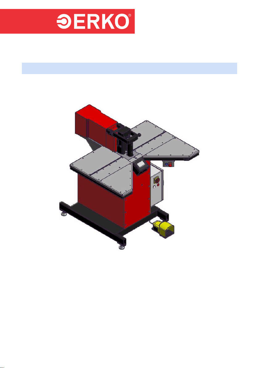
BUSBAR BENDING STATION
HG200

# VHG200020614
- 1 -
#VHG200020614
Thank you for purchasing our station.
Please read this operation manual and operation recommendations carefully.
TABLE OF CONTENTS
1. APPLICATION ....................................................................................2
2. TECHNICAL DATA.............................................................................2
3. STATION INSTALLATION .................................................................2
4. CONTROL PANEL..............................................................................3
5. OPERATION .......................................................................................4
5.1 START.................................................................................................4
5.2 WARRANTY PERIOD START............................................................5
5.3 BENDING ............................................................................................6
5.3.1 MEASURING SYSTEM RESET..........................................................7
5.3.2 OPERATING PARAMETERS AND INSERT CALIBRATION............9
5.3 CUTTING...........................................................................................10
5.4 CHANGE OF INTERFACE LANGUAGE..........................................11
5.5 COUNTER OF THE STATION RUNNING TIME AND DATE OF THE
NEXT INSPECTION ..........................................................................11
5.6 DATE AND TIME SETTING..............................................................12
6 TECHNOLOGY.................................................................................13
6.1 BENDING ..........................................................................................13
6.1.1 EQUIPPING THE BENDING STATION............................................13
6.2 CUTTING...........................................................................................16
6.2.1 EQUIPPING THE CUTTING STATION ............................................17
7 MAINTENANCE AND OPERATION RECOMMENDATIONS..........20
7.1 HYDRAULIC POWER PACK............................................................21
7.2 OPERATION AND MAINTENANCE.................................................23
7.3 MESSAGES.......................................................................................25
8 HEALTH AND SAFETY AT WORK INSTRUCTION.......... BŁĄD! NIE
ZDEFINIOWANO ZAKŁADKI.
9 SERVICE...........................................................................................28
10 DISPOSAL ..........................BŁĄD! NIE ZDEFINIOWANO ZAKŁADKI.
* Due to continuous product improvement, ERKO sp.j. reserves the right to make
design changes.
ISO 9001
ISO 14001

# VHG200020614
- 2 -
Please read the operation manual and health and safety at
work regulations before using the station.
The station is only used for operation with Al and Cu
busbars.
1. APPLICATION
HG200 is the busbar processing station with electronic angle measurement, equipped
with a touch panel. The basic functional features ensuring efficient and precise
operation are:
Possibility to adjust a bending angle within the range of 5-90° (bending
accuracy ±0.5°);
Engraved measuring ruler that enables a processed busbar to be positioned
with accuracy of 1 mm;
Control of processes with the foot switch;
Built-in reliable hydraulic power pack.
2. TECHNICAL DATA
Station weight
460 kg
Max. dimensions (L x W x H)
1226 x 1200 x 1240
Operating pressure
400 bar
Power supply
3x400/230 V 50 Hz, 1.68 kW
Control
24V DC
Power plug
16A 400V 3P N+E IP44(PCE
015-6v)
Protection degree
IP40
Range of processed busbars (Cu, Al) (TH x W)
Thickness: 5÷15; width:
50÷200 mm
Bending range
5÷90°
Operating temperature
5÷40 °C
3. STATION INSTALLATION
The station should be positioned on the hard and even surface and levelled.
The adjustable levelling feet make the station levelling easy. When the station
is positioned, please pay attention that the station rests securely on all 4 feet.
# VHG200020614
- 3 -
Use of the station on an inadequate surface may result in the station frame
deformation and problems during processing of busbars (in achieving the
accuracy offered by the manufacturer). In extreme cases, failure to follow the
above may result in the station damage.
Connect the station to the power supply system. The power supply system
parameters should be in accordance with the applied standards. A five
conductor power cable (L1, L2, L3, N, PE) is required for correct operation. The
phase sequence does not matter when the station is connected. When a four
conductor power cable is used, it is required to connect a jumper between the
PE and N conductor in the supply socket.
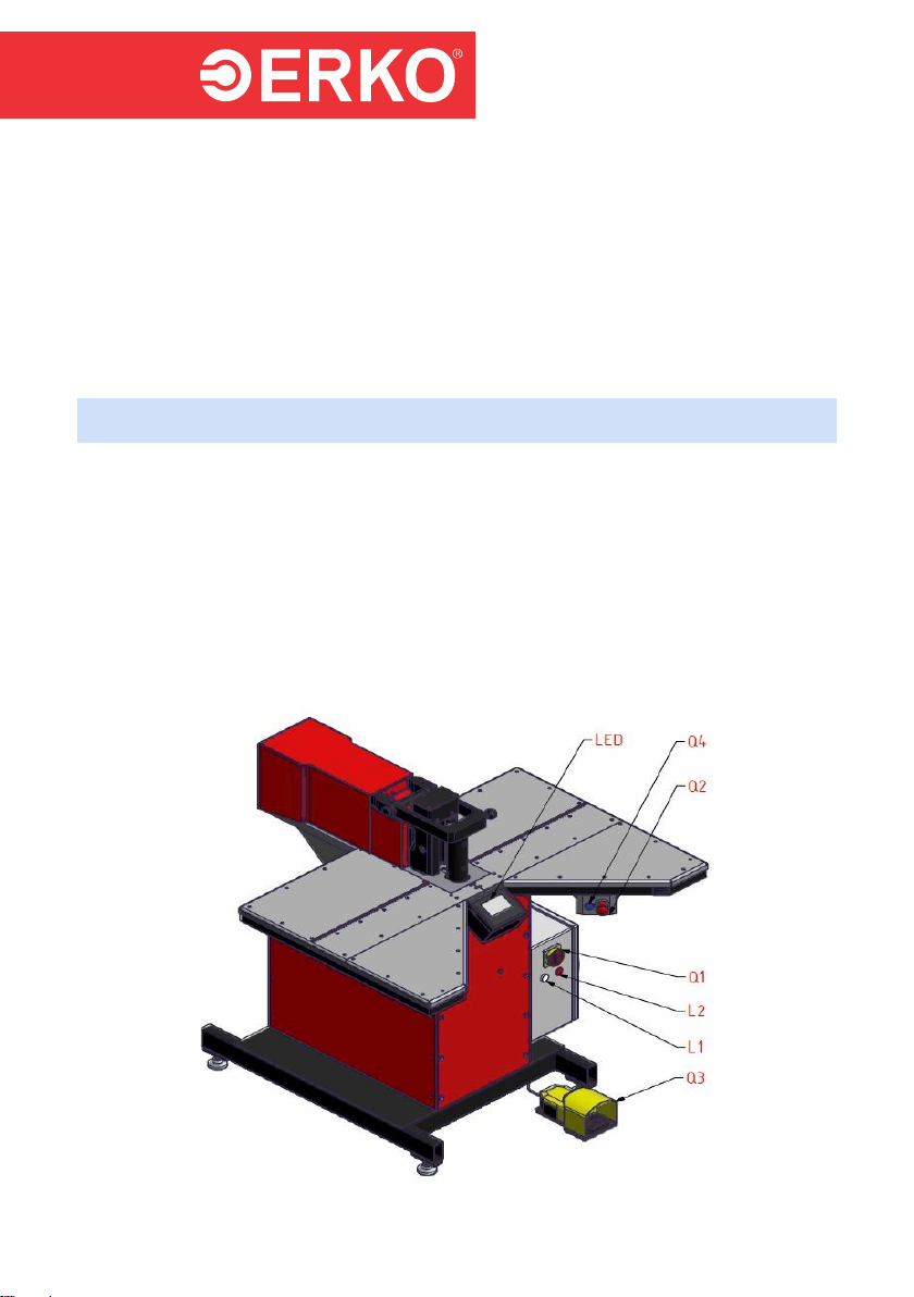
4. CONTROL PANEL
The control panel consists of the following elements:
Q1 Main switch used to start the station.
Q2 Emergency stop button.
Q3 Foot switch fulfils the function of the operating switch.
Q4 "RESET” button is used to start the safety system.
L1 White indicator lamp informs of correct power supply.
L2 Red indicator lamp informs of reaching the maximum oil operating
temperature.
LED Operator panel with the touch screen enables the station operation.
Fig. 1.

# VHG200020614
- 4 -
5. OPERATION
NOTE: The manufacturer reserves the right to change the operator panel graphics
depending on the software version.
5.1 START
To start the station, set the main switch (Q1) to position I. After setting the main switch
(Q1), the software loading and the station testing process is started. The operator
panel will show the screen with the login button (fig. 2) which, when touched, will show
the login window (fig. 3). To login, touch the white field with asterisks. Pressing the
field will show the numeric keypad (fig. 4). Using the keypad, enter the operator
password and confirm with the “ENTER” key. When an incorrect password is entered,
the window with the error message will be displayed (fig. 5). In such a situation, when
this message disappears, press the field with asterisks on the operator panel again
(fig. 3) and enter the correct password and confirm with the “ENTER” key. After correct
login, the message informing about the necessity of checking the safety system with
the “RESET” button will be shown (fig.6). After pressing the “RESET” button, the
station is ready for operation and the station enters the screen with the operation
selection (fig.7).
THE PASSWORDS PROGRAMMED FOR THE OPERATING PERSONNEL:
The factory set password for an operator is 159 and cannot be changed.
The factory set password for resetting the station measuring system is 1231 and
cannot be changed.
Fig. 2 Fig. 3

# VHG200020614
- 5 -
Fig. 4 Fig. 5
Fig. 6. Fig. 7.
When other messages are displayed or the above-mentioned messages are not
displayed, switch off the station with the main switch (Q1), wait for about 15 seconds
and proceed with the station start procedure again. If you failure to start the station
again, please contact the service personnel.
5.2 WARRANTY PERIOD START
When the station is started for the first time, the station warranty period start menu
appears after pressing the LOGIN button. After pressing the button, the window
that enables the warranty period start to be accepted will appear.

# VHG200020614
- 6 -
When you press the “NO” button, you will return to a previous window. When you
press the “YES” button and enter the password (159), the station switches to
cyclic operation mode. Counting the time interval to the technical inspection is
started.
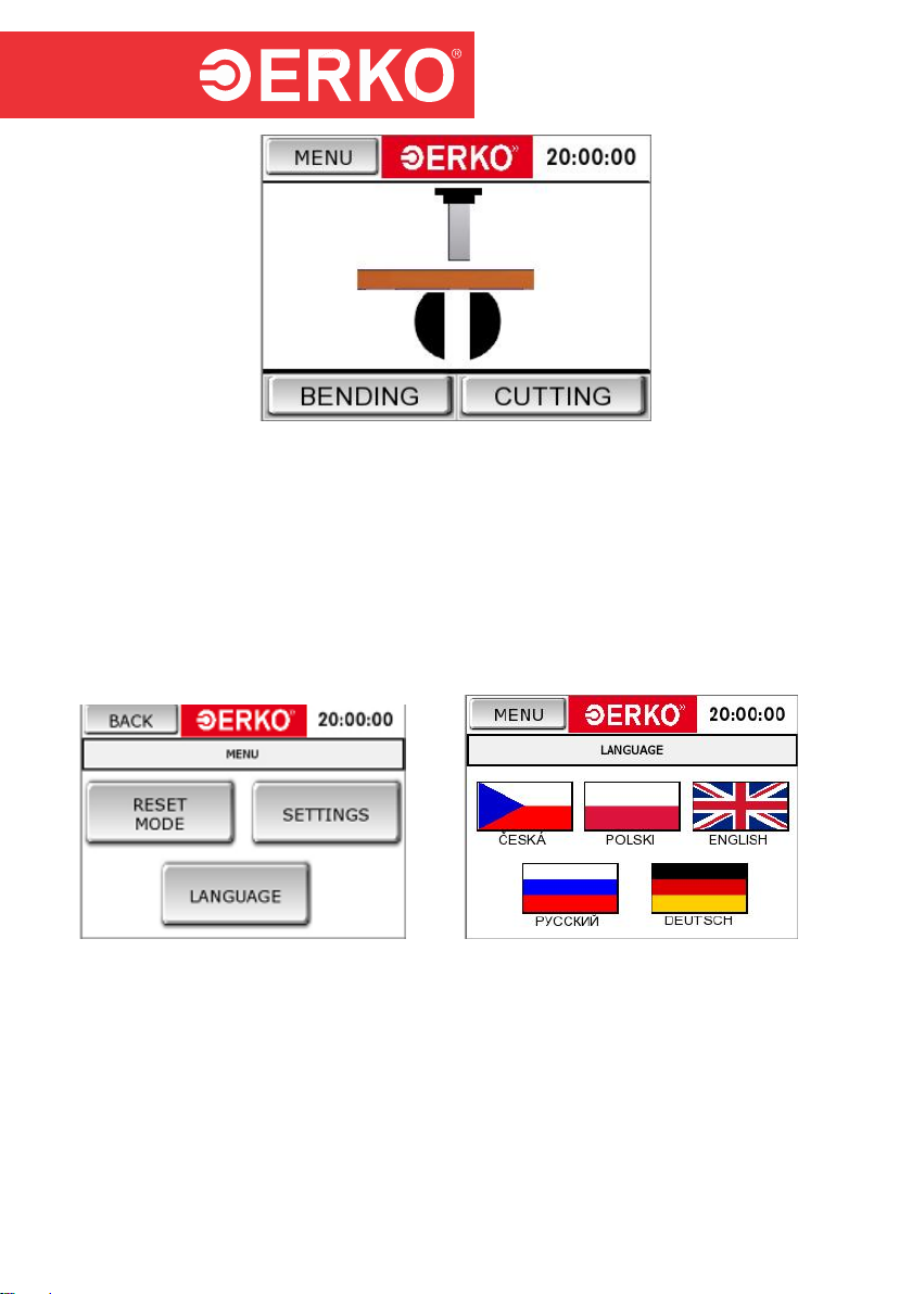
5.3 BENDING
To proceed with the bending process:
Start the station in accordance with the procedure set out in item 5.1.
Go to the bending mode (fig. 7) or during normal operation press the
BENDING button at the bottom of the screen (fig. 8).
Find the reference point of the measuring system ("REF" is displayed in the
"CURRENT ANGLE" field (fig. 8)). To find the reference point of the encoder,
bend the rollers of the angle measuring insert (the insert must be connected
to the installation socket). The operation should be completed with the
appearance of an angle value (fig. 9). Values in the manual are represented
by the “#” sign.
To specify the bending angle, enter the value edition using the button located
next to the yellow field entitled “SET BENDING ANGLE” (the default value
displayed is a dimension that was used during the last bending). Using the
displayed numeric keypad enter a bending angle value. Confirm the edition
with the “ENTER” button (fig. 10).
Specify the material type to be bent (fig. 12, AL - aluminium, CU - copper).
Insert a busbar into the working space.
Determine the distance from the bending edge to the punch axis with the
scale engraved on the table top.
Press and hold the foot switch (Q3) to start the bending cycle. When the
operation is finished, the piston rod returns automatically to the initial position.
To repeat the operation, release the foot switch and press it again.
Releasing the foot switch during the cycle results in the operation interruption
and return movement of the piston rod to the start position (performance of
the next bending is only possible after the piston rod returns to the start
position).
Fig. 8. Fig. 9.

# VHG200020614
- 7 -
Fig. 10. Fig. 11.
Fig. 12. Fig. 13.
To accelerate and improve working comfort, the station is equipped with two additional
functions. The first function is the possibility of entering one’s own bending angle
correction, where a user may enter a correction value using the numeric keypad after
pressing the grey field next to the "ANGLE CORRECTION" field (fig. 12).
The second function entitled "FAST CYCLE" (fig. 11) enables a busbar bending in a
shorter time, but without overbending. Bending with overbending is performed during
the first bending to determine a springback value of a busbar being bent. Then,
activate the "FAST CYCLE" function by pressing the button (fig. 11). Thereafter, the
program memorizes the overbending value and it bends to an angle considering a
correction during the next bending. This function significantly accelerates operation.
When an angle value or material is changed, the correction is cancelled and
determined again during the first bending.
Note: Connection and disconnection of the communication cable of the bending insert
is only permitted when the station power supply is switched off.
The insert delivered with the station is calibrated with the program. In case it is
necessary to replace the insert, a new one must be calibrated. To do this, contact the
authorized service.
5.3.1 MEASURING SYSTEM RESET
The purpose of the measuring system reset is to calibrate measuring elements of the
station.
Only the bending insert can be calibrated.

# VHG200020614
- 8 -
To reset the measuring system:
Start the station in accordance with the procedure set out in item 5.1.
Press the “MENU” button located in the left upper corner of the panel (fig. 3).
Press the “RESET MODE” button (fig. 14).
The numeric keypad will appear (fig. 15) where the reset password must be
entered (the reset password is 1231), and then confirmed with the “ENTER”
button.
The station enters the reset mode (fig. 16).
Fig. 14. Fig. 15.
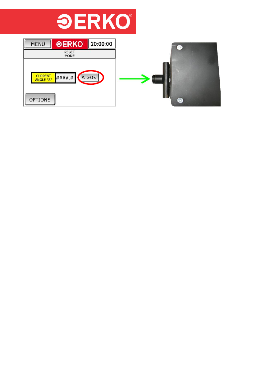
Fig. 16.
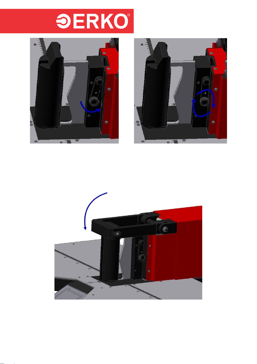
Using a flat element, adjust the levers in the parallel position to the measuring
insert body (fig. 18). Holding the immovable levers, press the "Reset" button on
the panel (fig. 17).
# VHG200020614
- 9 -
Fig. 17. Fig. 18.
When calibration is finished and a flat element is taken away from the measuring
levers, a value displayed on the operator panel takes a negative value different
from zero.
To check for correct calibration of the measuring insert, put the flat element again
and check if a value displayed on the operator panel is 0.
Note: The "TECHNICAL INSPECTION RESET" button is active when the station has
been operating for the period after which the manufacturer recommends a technical
inspection.
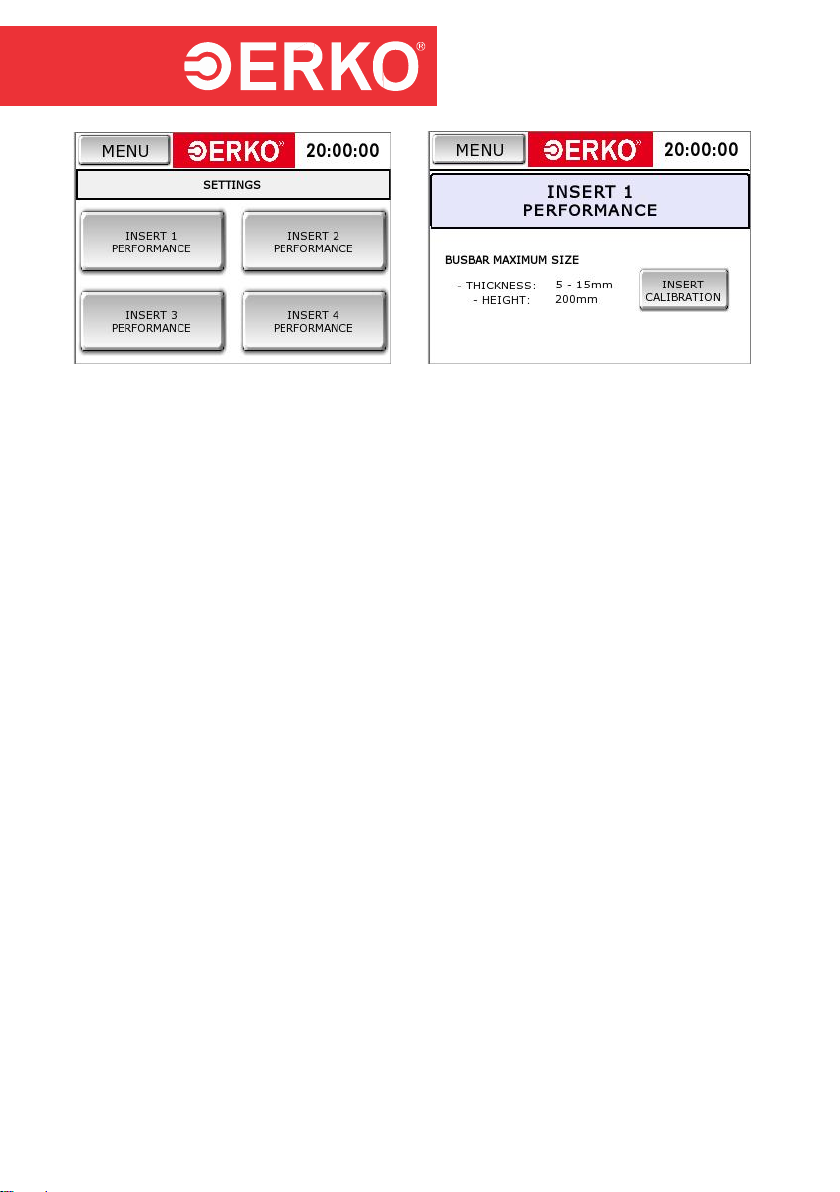
5.3.2 OPERATING PARAMETERS AND INSERT CALIBRATION
Depending on the range of bent busbars and bending parameters, i.e. bending radius,
busbar thickness etc., it is required to use different bending inserts. The HG200 station
offers this possibility. As standard, it is equipped with the insert suitable for a bar with
maximum height of 200 [mm] and thickness of 15 [mm]. At the customer’s request, it is
possible to make a special insert according to the instructions if there are no design
limitations.
To use the settings:
Start the station in accordance with the procedure set out in item 5.1.
Press the “MENU” button located in the left upper corner of the panel (fig. 3).
Press the “SETTING” button (fig. 14).
Select the insert number (fig. 19).
Enter the insert calibration (fig. 20). The password to change the insert
parameters will be provided by the manufacturer if required.
# VHG200020614
- 10 -
Fig. 19. Fig. 20.
Note: When the bending insert is replaced with a different one, it is to be
parameterised with the station software ("INSERT CALIBRATION" fig. 20). To do this,
please contact the ERKO authorized service.
5.3 CUTTING
To proceed with the cutting process:
Start the station in accordance with the procedure set out in item 5.1.
Go to the cutting mode (fig. 7) or during normal operation press the CUTTING
button at the bottom of the screen (fig.8). The cutting mode screen is shown
in figure 21.
Insert a busbar into the working space.
Determine the distance from the cutting edge to the knife axis with the scale
engraved on the table top.
Press and hold the foot switch (Q3) to start the cutting cycle. When the
operation is finished, the piston rod returns automatically to the initial position.
To repeat the operation, release the foot switch and press it again.
Releasing the foot switch during the cycle results in the operation interruption
and return movement of the piston rod to the start position (performance of
the next cutting is only possible after the piston rod returns to the start
position).
# VHG200020614
- 11 -
Fig. 21.
5.4 CHANGE OF INTERFACE LANGUAGE
To change a user interface language:
Switch on the station power supply and follow in accordance with item 5.1.
Press the “MENU” button located in the left upper corner of the panel (fig. 8).
Press the “LANGUAGE” button (fig. 22).
Select a language by touching the suitable flag on the screen (fig. 23).
Fig. 22. Fig. 23.
5.5 COUNTER OF THE STATION RUNNING TIME AND DATE OF THE NEXT
INSPECTION
To read the station running time and a date of the next technical inspection:
Press the “MENU” button located in the left upper corner of the panel (fig. 8).
Press the “RESET MODE” button (fig. 22).
After entering the reset password in the dialogue window, press the
“OPTION”button.

# VHG200020614
- 12 -
After pressing the button the dialogue window with the counter of the station
running time and a date of the next technical inspection will show.
Fig. 24. Fig. 25.
5.6 DATE AND TIME SETTING
To set time:
Press the “MENU” button located in the left upper corner of the panel (fig. 8).
Press the “RESET MODE” button (fig. 22).
Click the clock in the right upper corner to start the clock setting panel.
Fig. 26.
# VHG200020614
- 13 -
6 TECHNOLOGY
6.1 BENDING
When the station has just been started, carry out the operations according to
item 5.1
Equip the station with the bending mandrel and measuring insert according to
item 6.1.1 and enter the settings according to item 5.2
Slide a busbar in a space between the mandrel and measuring insert and
slide a busbar close to the mandrel.
Close the clamp (fig. 33).
Press and hold the foot switch (Q3) to start the bending cycle. When the
operation is finished, the piston rod returns automatically to the initial position.
To repeat the operation, release the foot switch and press it again.
Releasing the foot switch during the cycle results in the operation interruption
and return movement of the piston rod to the start position.
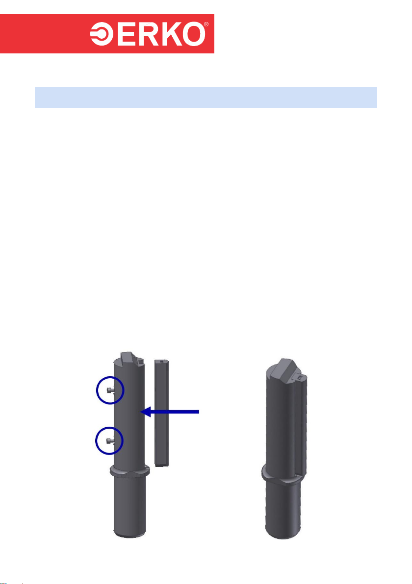
6.1.1 EQUIPPING THE BENDING STATION
To equip the bending station:
Mount the suitable bending radius in the bending mandrel and fasten it with
two bolts (fig. 27). The mounted mandrel is shown in figure 28.

# VHG200020614
- 14 -
Fig. 27. Fig. 28.
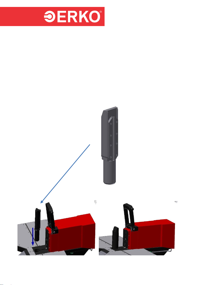
Slide the bending mandrel into the hole in the body (fig. 29) (fig. 30).
Fig. Bending mandrel
Fig. 29. Fig. 30.
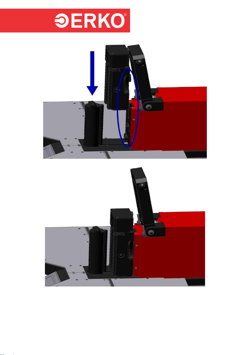
Mount the bending insert using the guiding elements (fig. 31) (fig. 32).
# VHG200020614
- 15 -
Fig. 31.
Fig. 32.
Connect the bending insert.

# VHG200020614
- 16 -
Fig. 33.
Close the safety clamp (fig. 34).
Fig. 34.
6.2 CUTTING
In case the station has just been started, carry out the operations according to
item 5.1
# VHG200020614
- 17 -
Equip the station with the cutting mandrel and cutting insert according to item
6.2.1.
Slide a busbar in a space between the mandrel and cutting insert and slide a
busbar close to the mandrel.
Close the clamp (fig. 34).
Press and hold the foot switch (Q3) to start the cutting cycle. When the
operation is finished, the piston rod returns automatically to the initial position.
To repeat the operation, release the foot switch and press it again.
Releasing the foot switch during the cycle results in the operation interruption
and return movement of the piston rod to the start position.
6.2.1 EQUIPPING THE CUTTING STATION
To equip the cutting station:
Slide the cutting mandrel into the hole in the body (fig. 35) (fig. 36).
Fig. Cutting mandrel.
Fig. 35. Fig. 36.

# VHG200020614
- 18 -
Mount the bending insert using the guiding elements (fig. 37) (fig. 38).
Fig. 37.
Fig. 38.
Catch the lock (fig. 39) and fasten (fig. 40).
# VHG200020614
- 19 -
Fig. 39. Fig. 40.
Close the safety clamp (fig. 41).
Fig. 41.
Table of contents


