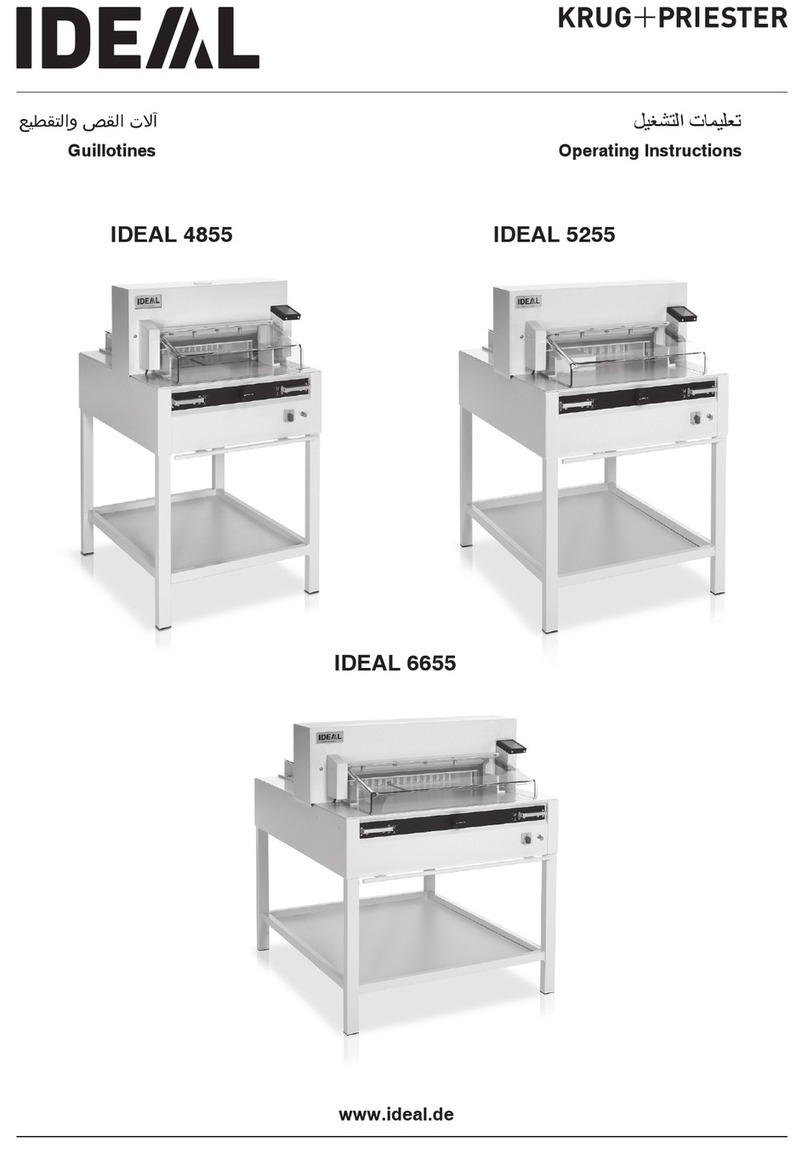
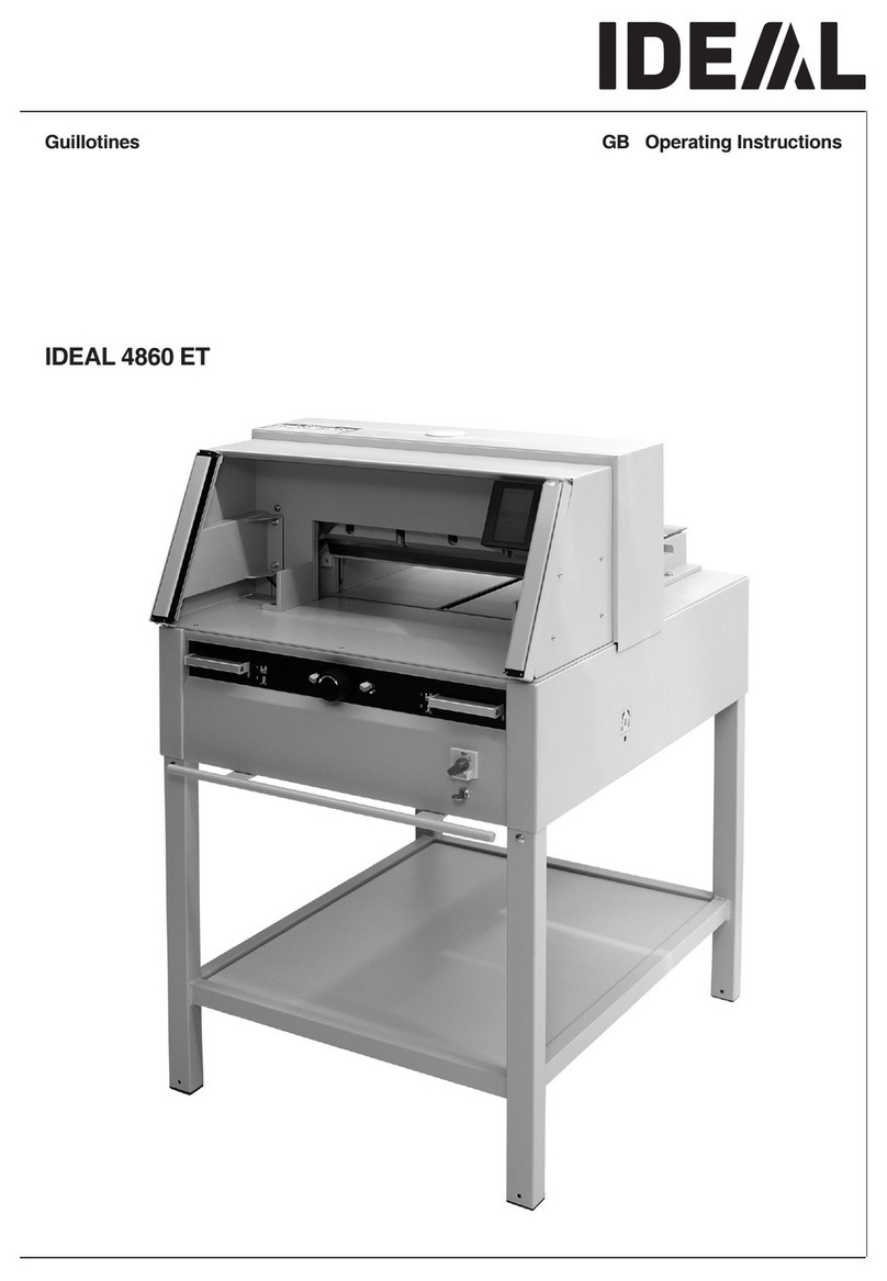
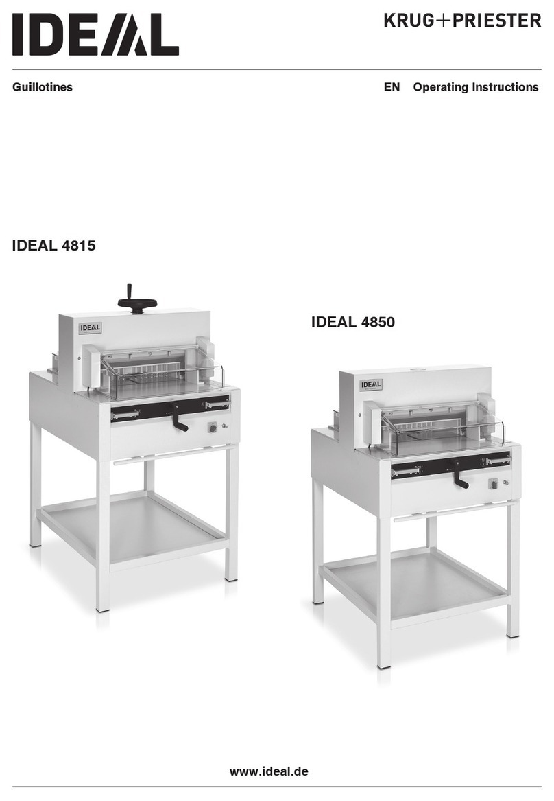
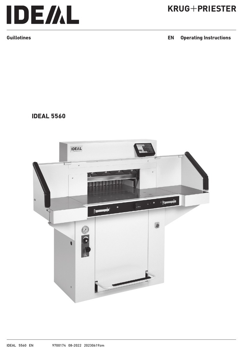
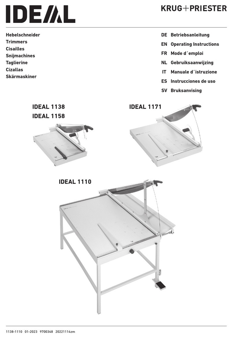
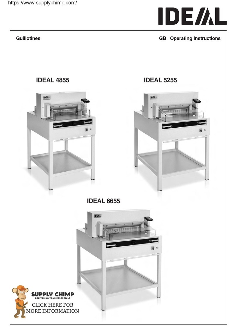
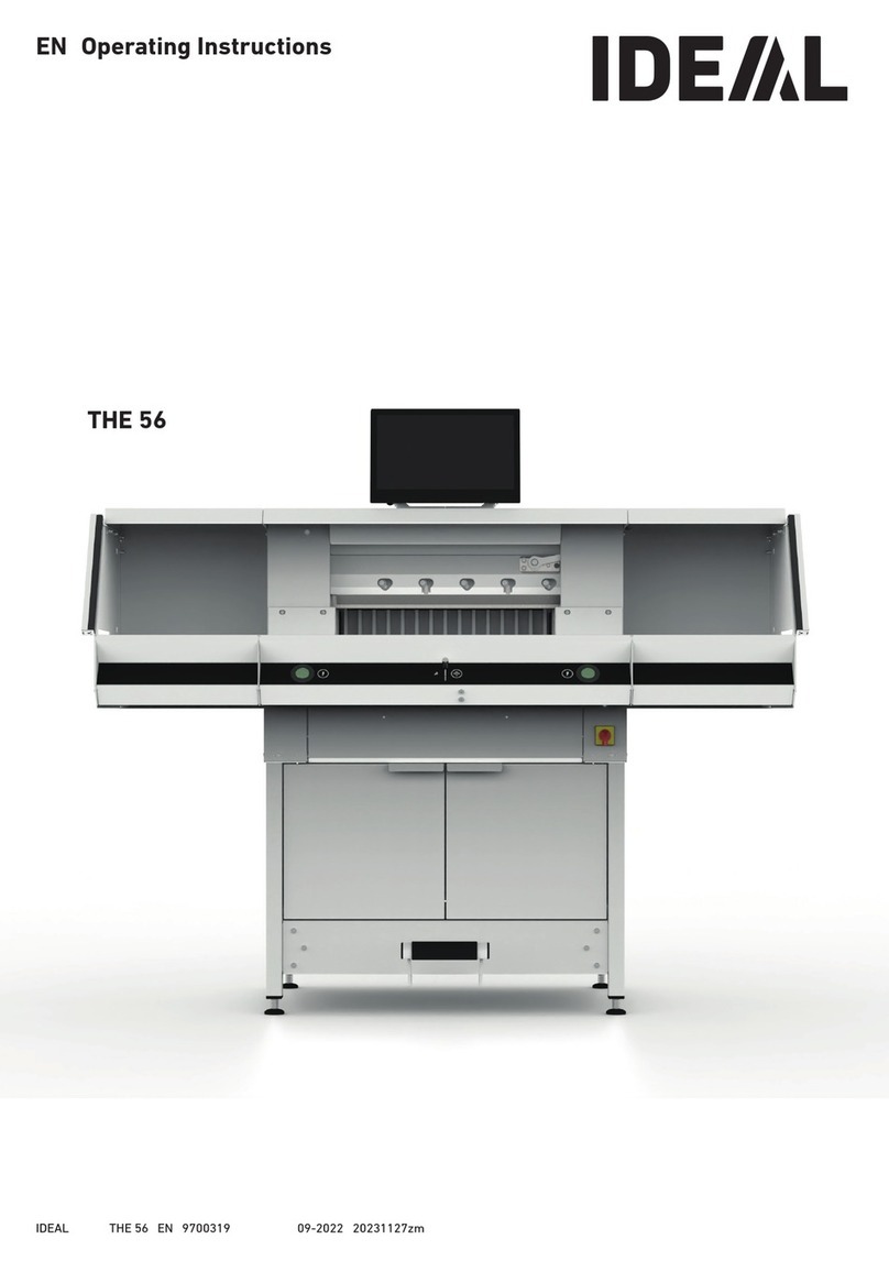
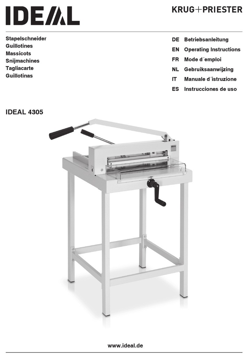
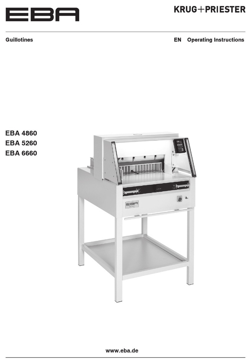
KRUG+PRIESTER EBA Series User manual

EN Operating InstructionsGuillotines
www.eba.de
EBA 5560

- 2 -
Table of Contents
Safety precautions 3
Intended use 4
Installation 8
Startup 9
Operation 12
Operating elements 16
Blade and cutting stick replacement 24
Maintenance and cleaning 35
Annual inspection / Safety test 37
Possible malfunctions 38
Accessories 42
Technical data 43
EC-declaration of conformity 46

- 3 -
Safety precautions
Please read these operating instructions before putting the machine into
operation and observe the safety precautions.
The operating instructions must always be available.
Children must not operate the machine!
Do not reach beneath the blade!
Never leave the blade unattended!
Do not extract or transport the blade without
protection! (See page 27 and 29).
Danger! Risk of injury!
Do not cut hard materials or materials which
may splinter!

- 4 -
Intended use
The machine is designed for cutting stacks of
paper to a specied size.
This machine is constructed for "one-man
operation" only!
Warning! Clips or similar damage the
cutting blade.
Safety precautions / Intended use
Do not use any spray cans with flammable
content near to the cutting machine!
Do not use any flammable cleaning agents.

- 5 -
Disconnect from the mains before starting any
service work or before removing the panels!
Replacement of blade and cutting stick may
be performed only when the main switch is
switched off!
Safety precautions

- 6 -
B
A
B
A
Protect mains cable against heat, oil and
sharp edges!
Standard machines are factory-set as
follows:
• Voltage 230 V (120 V) 1 phase
• Frequency 50 Hz (60 Hz).
All components which could endanger the
operator are covered by a guard (B)!
Do not operate the machine without the
following safety devices:
• Safety beam guard (A)
• Panels, tightly screwed (B).
The cutting action, which is dangerous to the
operator, is protected by a two-handed
control system (B) and safety beam guard
(A).
Safety precautions

- 7 -
When not in use for a longer period switch
off. (Main switch to "0").
Danger!
Blade must always be covered by the
pressing bar.
Clamping Blade
OK
OK
Safety precautions

- 8 -
A
A
B
The machine is mobile on castors. Align the
machine as followes:
• Align machine with water level and adjust
accordingliy.
4 x screws size 19 (A).
• Reference area machine table (B).
Installation

- 9 -
A
The machine is delivered ready for
operation. Side tables (A), left and right are
available as an option. Assembly
instructions are included.
Startup
Plug into socket.
Installation / Startup

- 10 -
B
A
C
DE
STOP
The machine may only be operated, if
the operating instructions and the safety
instructions have been understood.
Before each use, check the safety
equipment for completeness and
functionality.
• All covers have to be mounted (A).
• Safety beam guard must be mounted (B).
• The release for cutting is allowed only if
the two-hand safety device is operated at
the same time (C)
• Safety light beam:
If the test rod (E, tool kit) is held into
the
protectiveeld(D),anactivatedwork
cycle must be stopped immediately.
We recommend you keep a record of your
test results.
Startup

- 11 -
C
B
A
B
A
A
D
C
Position the main switch to "I" (A).
Blade locking facility (B) must be pulled out.
Press S(C). Machine will
automatically go to the start position.
The machine is now ready for use.
The measurement is set either with the
handwheel (A) or by programming (B) the
cutting measurements. Measurement is
shown on the display in inches or cm (B).
Display (C) is pivotable. By loosing the allen
head screw (D), (allen wrench is in the tool
box) the display can be pivoted within the
elongated hole. Tighten allen screw again.
Startup

- 12 -
C
B
A
C
B
A
Optical cutting line indicator:
Optical cutting red line (A), indicates the
position of the cut. Blade cuts on the front
edge of the light beam.
Mechanical cutting line indicator:
The clamp (B) can be used as cutting line
indicator for cutting. Pre-clamping can be
performed using the foot pedal (C).
Only use the optical cutting line indicator and
mechanical cutting line indicator when no
exact cut is required.
Position the paper on the backgauge (A)
and side lays left or right (B). To move paper
stacks, please use the paper knock-up block
(C) provided. (Run backgauge to the front
for turning the paper stack).
Operation

- 13 -
A
B
A
B
A
Clamp plate:
A clamp plate (A) is tted to the machine
to prevent pressure marks on sensitive
material.
To dismantle:
• Remove the clamp plate (A) by turning the
screwdriver (found in tool box) in the space
between the clamp and clamp plate.
The remaining cut is 3,2 cm.
To mount:
• The clamp plate (A) is inserted to the top
into the clamp (B).
The remaining cut is 6 cm
(manual - handwheel), automatically 8 cm
Air table
It is easier to position large stacks of paper
when the airtable (A) is switched on.
Operation

- 14 -
B
A
A
B
Setting clamping pressure
If necessary, set clamping pressure with
setting wheel (A). If a cutting process has
been activated, the oil pressure can be seen
on the oil pressure indicator (B).
The clamp moves automatically when
cutting is activated. The paper can be
pressed in advance, with the foot pedal (A).
Cutting is activated by pressing both buttons
(B) on the front table.
Operation

- 15 -
B
A
A
Cutting activation
Do not reach into the cutting area when the
blade is in motion.
A cut can only be activated when the
specied size is approached.
• Release the photo-electric beam guard
(A).
• Press both actuators of the safety
two-handed control system (B)
simultaneously and keep them pressed
until the paper is completely cut.
Cutting stop or interruption:
Release both actuators of the two-hand
control (A).
Operation

- 16 -
XND O
M
b
Operating elements
A- Safety light beam
B- Safety two-handed control system
clamping and cutting
C- Air table On-Off
D- Backgauge control
E- Foot pedal
F- Main switch
G- Hand-wheel for backgauge setting
H- Blade locking
I- Backgauge
J- Side lay left and right
K- Clamp pressure
L- Clamp pressure adjustment
Start machine
• Main switch Fto position "I".
Start screen appears
The following functions are changeable:
Brightness
CM/INCH
Touchtone volume
Language
Display / status photocell b green - red
•Press START M backgauge I moves
to the rear and searches for the reference
position, wait until a measurement
is shown in the display D
5560 = 57.00 cm, 22.441 inches
• The DIN and free programmable
measurements are recallable with the
respective buttons X.
Memory 1: A2, A3, A4, A5,
Memory 2: A6, A7, B3, B4
Memory 3:
Memory 4:
and in inch
Memory 1: 4¼“, 5 ½“, 7“, 8 ½“
Memory 2: 11“, 12“, 14“, 17“
Memory 3:
Memory 4:
Operation / Operating elements

- 17 -
XNP O
EFG
•In memory 3 + 4 (mm and inch) no
measurements are saved. Until a rst input of
data the following will be shown in the
corresponding elds: . The
measurements entered remain stored.
Theycannotbedeletedbutoverwritten.
HowtoprogramMemory3and4
Press the memory button Xto enter the
memory platform (3 or 4). Enter the required
measurements or overwrite them. Press the
button and keep it pressed until
an acoustic signal sounds, the
measurements have been saved now.
Warning!
Before storing or cutting a measurement
please check if the correct measurement scale
(cm or inch) see above is stored.
(5560 = 57.00 cm, 22.441 inches)
Is shown on the screen see N.
After 30 minutes the machine (ABC D)
switches to energy-saving mode.
The machine is reactivated by touching the
keypad area O.
Bright LEDs illuminate the working area (D).
The LED button (E) has 3 switching steps
Press 1 x brightness 3
Press 2 x brightness 2
Press 3 x brightness 1
Light OFF F.
Optical cutting line indicator A (ON/OFF) G
Operation

- 18 -
P O
Cutting activation
Warning!
• Run backgauge to the front for turning the
paper stack
• Do not interrupt the upward movement of the
blade by performing switching procedures
•Wait until the display is green before
activating a cut
• Blade must always be at the top and be
covered by the clamp. Do not touch the
blade (see safety information on page 34).
Risk of injury!
Cuttingtospecieddimensions
• Press MANUAL
• Enter dimension on the numerical
key pad O Measurement is shown in red
(If a wrong dimension is entered this can be
corrected by pressing the CLEAR button)
• Press START P dimension is
approached, Measurement is shown
in green
• Insert paper and move by means of the
stacking angle Qto the backgauge Iand
side lay on the left J
• Release the cut.
Cut according to markings
•Press MANUAL
• Adjust the backgauge with the
hand-wheel
Gto the back
• Insert paper and move by means of the
stacking angle Qto the backgauge Iand
side lay on the left J
• Turn the hand-wheel Gto the right until the
marking on the paper to be cut is below the
cutting line indicator
•The further the hand-wheel G
is turned to the right, the quicker the
backgauge moves. If the hand-wheel is
turned to the left the backgauge will return
quicker.
Operation

- 19 -
P R
OS
T
W
YXZ
Eject function
If EJECT Ris pressed instead of START P,
after inserting the measurement O, the
backgauge will advance forwards so that
paper can be removed. Finally the backgauge
moves to the last setting.
Multiple cut
•Enter the start dimension on the display O
•Advance to the measurement with the
START P
•Push the paper to the backgauge
•Press multiple cut T
•Multiple cut sign appears top left together
with the value 00.00 S
•Enter multiple cut measurement (appears in
red letters)
•Press START the backgauge advances
by the multiple cut size
•This is repeated everytime a cut is activated.
Exiting program-mode
•Press multiple cut T(yellow).
Multiple cut sign and value are deleted.
Calculator function X
• Calculate the desired measurement,
e.g. 40 - 2 = YZ and
the backgauge advances immediately to 38.
Operation

- 20 -
V
UProgramming
This control system enables you to store 99
programs with 99 programmable steps. One
step represents one measurement. After
entering the program numbers you are able to
change between several program steps with
the button jand b.
First gure on display U= program number.
Second gure on display V= program step.
Each program step corresponds to one
dimension. The indicated program step can
be overwritten at any time. These programs
remain stored when the machine is off.
Entering a program
• Press PROG EDIT "Load program no."
appears
• Enter program number 01 ... 99, with
(Top number Uon display = program
number)
•If measurement is shown on the display the
program is reserved, select another program
•Program step "01 Step" 00.00 V appears.
(Second gure on display V= program step.
•Enter dimension, or move the backgauge to
the desired measurement with the
hand-wheel
G
• Store the measurement ,next program
step appears.
•Enter the next measurement and with Enter
store the measurement etc.
•Should the entered program be required
immediately press PROG RUN
•Press Enter
•Press START
•Escape the program mode press MANUAL
Cancel a program
•Press PROG EDIT
•Scroll with PROG until "Delete program no."
appears
•Enter Program number
•Press Enter
•Press Enter .
Operation
Other manuals for EBA Series
2
This manual suits for next models
1
Table of contents
Other KRUG+PRIESTER Cutter manuals

KRUG+PRIESTER
KRUG+PRIESTER IDEAL 4705 User manual

KRUG+PRIESTER
KRUG+PRIESTER IDEAL 5255 User manual

KRUG+PRIESTER
KRUG+PRIESTER IDEAL 4815 User manual

KRUG+PRIESTER
KRUG+PRIESTER IDEAL 5560 User manual

KRUG+PRIESTER
KRUG+PRIESTER IDEAL 3005 User manual

KRUG+PRIESTER
KRUG+PRIESTER IDEAL 4860 ET User manual
KRUG+PRIESTER
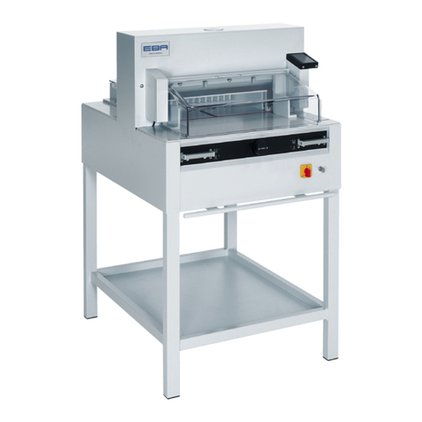
KRUG+PRIESTER EBA 4855 User manual

KRUG+PRIESTER
KRUG+PRIESTER EBA Series User manual

KRUG+PRIESTER
KRUG+PRIESTER IDEAL 4305 User manual

KRUG+PRIESTER
KRUG+PRIESTER IDEAL 1138 User manual