Copyright © 2005 wenglor sensoric gmbh
Step 6 —
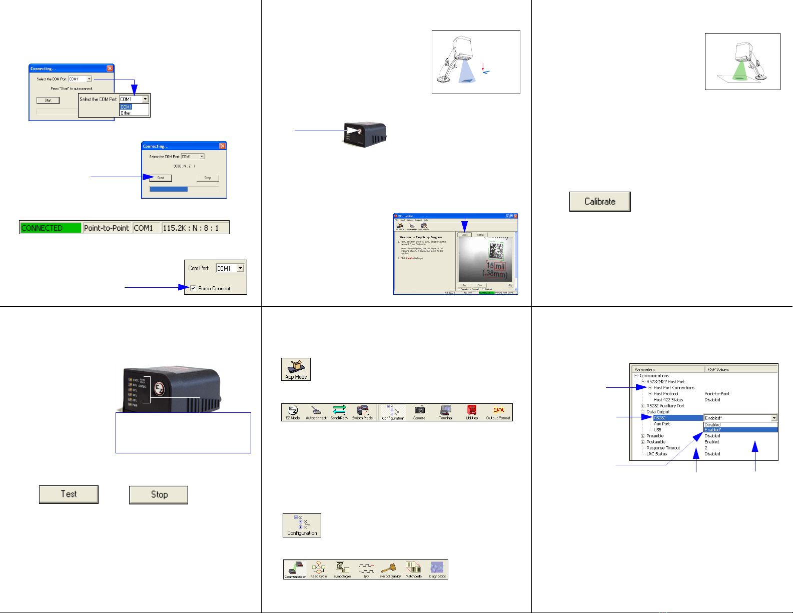
Autoconnect
Important: The Imager is in Continuous Read Mode by default. For best
results, be sure that no symbols are within the Imager’s field of view while
attempting to connect.
• Click Start when the Autoconnect dialog appears.
• If your communications port is not the default COM1, use the dropdown
menu to change your port.
When you are connected, you will see the green connection indicator in the
status bar at the bottom right of your screen:
• If the connection attempt fails, click the
Autoconnect
button, select a different
communications port, and try again.
• Once you have
chosen the correct
port, click Start to
connect.
Note: If your RS-232 host settings cannot
be changed to match the Imager’s settings,
check the Force Connect box.
Step 9 — Test Read Rate
This test will let you know the percent of good reads per images captured.
Testing by EZ Button
1. To start the read rate test,
hold down the
EZ
button
about three seconds until
you hear
three short
beeps
.
While the symbol is
being decoded, the read
rate LEDs will indicate
the corresponding read
rate percentage on the
back of the unit.
2. To end the read rate
test, press the EZ button
and quickly release.
Testing by ESP
1. Click the Test button to start the read rate test and Stop to end it.
If your symbol has been successfully decoded, its data and related
features will be presented under “Symbol Information.” Also, while the
symbol is being decoded, the read rate LEDs will indicate the corre-
sponding read rate percentage on the back of the unit.
2. To end the test, click the Stop button.
Testing by Serial Command
You can also start a test with the <C> or <Cp> command and end it
with the <J> command.
20%, 40%, 60%, 80%, 100%.
These LEDs represent the percentage
of good reads per images captured.
Step 7 — Locate the Symbol
Move the symbol or the Imager so that the blue
target pattern is centered over the symbol. At 2
to 3 inches, the pattern resembles an X. At 3 to
6 inches, the pattern resembles a V.
It is important for the whole symbol to fall within
the field of view (FOV) of the Imager. The field
of view is what appears in ESP’s Locate/Cali-
brate window.
Locate by EZ Button
If you are not connected to a host computer, the EZ button will allow you to
locate a symbol in the Imager’s FOV.
• Hold down the EZ button for about one second and release when you hear
one short beep. You will see the blue target pattern.
• Center the target pattern on the symbol.
Note: To end all EZ button functions, press the EZ button once and quickly
release.
Locate by ESP
In ESP’s EZ Mode, click the
Locate button to enable the target
pattern.
You will see the blue target pattern
projected from the front of the
Imager.
• Center the target pattern over
the symbol you wish to read.
• Click the Stop button to end the
Locate function.
Center on symbol
in field of view.
Target pattern shown as it would appear between 3 and 6 inches.
Step 10 — Configure the Imager
Using ESP
To make setup changes to the FIS-6300, click the App Mode button.
The following modes are accessible by clicking the buttons in the first row of
App Mode icons:
• Establish communications between ESP and the Imager by clicking the
Autoconnect button.
• Send or receive commands by clicking the Send/Recv button.
• Make changes to Camera options by clicking the Camera button.
• Access the Terminal window, where you can see symbol data and enter
serial commands, by clicking the Terminal button.
• Review status settings or make changes to operational commands by clicking
the Utilities button.
• Format data for output by clicking the Data Output Format button.
Click the Configuration button to display the second row of ESP icons.
From here you can make changes in the configuration trees that can be
accessed by clicking the buttons on the second row of icons in the ESP window.
For further details, see ESP Help in the pulldown Help menu.
Step 8 — Calibrate Settings
The Imager can be optimized by the EZ button,
ESP, or serial command. During calibration, the
Imager will flash its LEDs while determining the
best configuration for decoding symbol data.
Upon successful completion, a green LED pattern
will flash brightly and illuminate the symbol. If
unsuccessful, the Imager will emit 5 short beeps
and stop searching.
Calibrate by EZ Button
1. Hold down the EZ button for about two seconds and release when you
hear two short beeps.
2. The Imager will search through various camera and IP settings to
determine the best configuration for decoding symbol data.
Important: The object must be centered in the field of view for the calibration
process to be successful.
Note: To end all EZ button functions, press the EZ button once and quickly
release.
Calibrate by ESP
1. Click the Calibrate button in EZ Mode.
2. The Imager will search through various camera and IP settings to
determine the best configuration for decoding symbol data.
A successful calibration will display a green frame around the symbol, and
the following message will appear: “Uploading all reader parameters.” After
a moment the symbol’s data and related features will be presented under
the “Symbol Information” box below the image display window.
Calibrate by Serial Command
Send <@CAL> to the Imager to begin the calibration routine.
Step 11 — Make Menu Changes
and Save in ESP
To make changes to a configuration setting:
•Send, No Save. Changes will be lost when power is re-applied to the
Imager.
•Send and Save. This activates all changes in current memory and saves
to the Imager for power-on.
1. Left click on the
+to expand the
desired tree.
2. Double click on
the desired
parameter and
click once in the
selection box to
view options.
5. Right click on the
open screen and
select Save to
Reader to implement
the command in the
Imager.
4. Left click again on
the open screen to
complete your
selection.
3. Place your cursor
in the selection
box, scroll down to
the setting you
want to change,
and click once on
the setting.
Saving Options


