ermaf GP 40 ACU User manual
➔
www.docuthek.com
D GB NL RUS PL F E UA CN
© 2018 Elster GmbH · Edition 07.18
03251543 Safety
Please read and keep in a safe place
Please read through these instructions
carefully before installing or operating. Following the
installation, pass the instructions on to the opera-
tor. This unit must be installed and commissioned
in accordance with the regulations and standards
in force. These instructions can also be found at
www.docuthek.com.
Explanation of symbols
• , , , ... = Action
▷= Instruction
Liability
We will not be held liable for damage resulting from
non-observance of the instructions and non-com-
pliant use.
Safety instructions
Information that is relevant for safety is indicated in
the instructions as follows:
DANGER
Indicates potentially fatal situations.
WARNING
Indicates possible danger to life and limb.
CAUTION
Indicates possible material damage.
All interventions may only be carried out by qualified
gas technicians. Electrical interventions may only be
carried out by qualified electricians.
Persons under the age of 18 as well as persons with
reduced physical, sensory or mental capabilities or
lack of experience and knowledge are not allowed
to use, clean or service this device. Staying near the
device or its use is prohibited, even if said persons are
supervised or have been instructed on the safe use of
the devices and are aware of the resulting dangers.
Conversion, spare parts
All technical changes are prohibited. Only use OEM
spare parts.
Contents
Operating instructions
GB-1
Translation from the German
D
GB
NL
RUS
PL
F
E
UA
CN
Heater GP 40 ACU
Heater GP 40 ACU ......................
Contents ..............................
Safety.................................
Checking the usage .....................
Installation ............................
Tightness test ..........................
Wiring ................................
Connection diagram......................4
Burner Chip Card (BCC) ..................6
Setting the switch-on delay ................6
Commissioning.........................6
ACU control panel ....................... 7
Switching on ........................... 7
Switching off ........................... 7
Setting mode ...........................8
Adjusting the heater.....................8
Cleaning .............................0
Assistance in the event of malfunction ....
Maintenance ..........................8
Checking the safety functions and burner
operation.............................0
Accessories ..........................0
Spare parts ...........................
Technical data ........................
Declaration of conformity ...............
Logistics .............................
Goods return form . . . . . . . . . . . . . . . . . . . . . 4
Contact ..............................4
Safety
Contents
GB-2
D
GB
NL
RUS
PL
F
E
UA
CN
Checking the usage
GP 40
Heater with direct, open combustion for animal sheds
and horticultural greenhouses. Depending on the
type and setting, the heater can be operated with
natural gas or LPG (propane/butane).
This function is only guaranteed when used within
the specified limits– see page23 (Technical data).
Any other use is considered as non-compliant.
Type code
Code Description
GP Heater
40 Capacity 40 kW, jet length 40 m
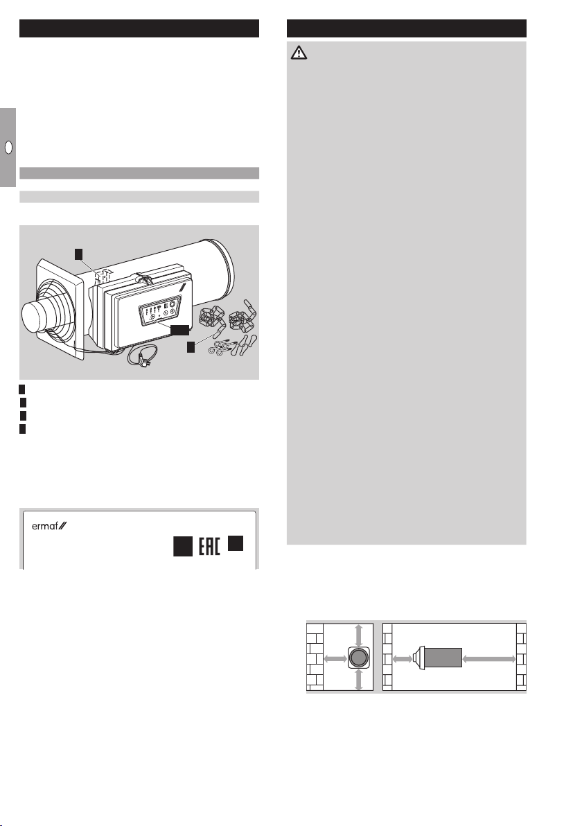
Part designations
MODE RESET ON/OFF
4
1, 2
3
Burner control unit ACU
Gas combination control CG
Vane
4Assembly accessories
Type label
Air circulation, electrical connection rating, voltage,
rated heat input, gas type, category, supply pressure,
burner pressure, enclosure: see type label.
Elster s.r.o.
Dr. A. Schweitzera 194
SK-91601 Stará Turá
UA.TR012-13
● Before installation, check whether the device is
suitable for the regional gas type and the specified
limits, see type code and page23 (Technical
data).
Installation
DANGER
Danger of death! Gases are generated during the
storage of slurry which remain partly dissolved in
the liquid. If the slurry is strongly agitated during
mixing and purging, poisonous, explosive gases
such as hydrogen sulphide and methane are re-
leased. If an ignition source is present, the released
gas can explode.
To avoid damage during operation, please observe
the following:
– Switch off the heater before mixing and purging
the slurry.
– Close the slide valves when storing slurry out-
side.
– The fan for the air supply must not be part of a
closed pipe system.
– The space to be heated must be adequately
ventilated.
For mechanical extraction equipment: at least
10m3/h of air per installed capacity.
In the case of natural ventilation, the structure
must have two apertures with a free opening
area of 60x B in cm2. “B” is the installed capac-
ity in kW. Replacement of the full air volume per
hour is thus ensured.
– In the case of natural ventilation, the maximum
allowable total capacity of the heater is 1kW
per 20m3of volume.
– Respect the safety distance of the heater to
inflammable materials, see “Installation position”.
– Consult your fire insurance provider and/or local
fire protection engineer to assess the foresee-
able, general risk of fire.
– For cleaning, care and maintenance, note the
applicable national regulations and directives.
– No condensation permitted. Comply with ambi-
ent temperature, see page23 (Technical data).
Installation position
▷ To ensure that the vane functions faultlessly, in-
stall the unit in the horizontal position.
▷
Note the safety distance to walls and inflam-
mable materials.
> 1m
> 0,8m
> 1m
> 3 m> 1m
▷ Ensure sufficient free space around the device.
There must be no obstructions in front of the inlet
and outlet side of the heater.
▷ To avoid overheating, do not cover the electric
motor.
GB-3
D
GB
NL
RUS
PL
F
E
UA
CN
Connecting the gas supply
▷
If the heater is suspended on chains, use an
approved flexible gas hose.
Disconnect the system from the electrical power
supply.
Shut off the gas supply.
Remove the sealing plug at the inlet tube of the
gas combination controlCG.
4 Connect the gas pipe with threaded connec-
tion (R½" external thread) or gas hose, see
page 20 (Accessories), to the inlet tube of
the gas combination control.
▷ Use approved sealing material only.
▷ Note the maximum inlet pressure, see page23
(Technical data).
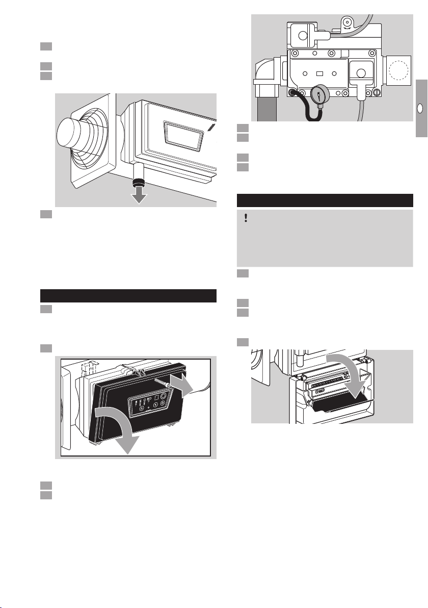
Tightness test
Disconnect the system from the electrical power
supply. The mains plug may only be pulled out
once the device has been switched off.
▷ The valves are closed when de-energized.
Open the cover of the ACU.
MODE RESET ON/OFF
▷ To do so, turn the cross-head screw anti-clock-
wise several turns so that it can be lifted.
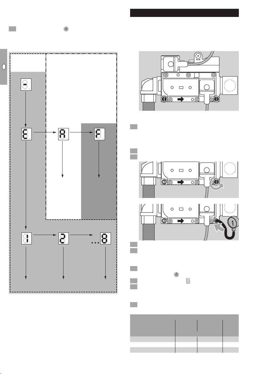
Open the test point for puon the CG.
4 Connect a pressure gauge to test point pu.
+ -
+
-
0
pu
5 Switch on the power supply.
6 Release the gas supply.
▷ Inlet pressure pu max.= 70mbar.
7 Shut off the gas supply.
8 Check the gas pressure on the pressure gauge.
▷ The pressure must not drop.
Wiring
CAUTION
Danger of electric shocks!
– Before working on possible live components,
ensure the unit is disconnected from the power
supply.
Disconnect the system from the electrical power
supply. The mains plug may only be pulled out
once the device has been switched off.
Shut off the gas supply.
Open the housing cover of the ACU.
▷ To do so, turn the cross-head screw anti-clock-
wise several turns so that it can be lifted.
4 Open the cover of the burner control unit.

GB-4
D
GB
NL
RUS
PL
F
E
UA
CN
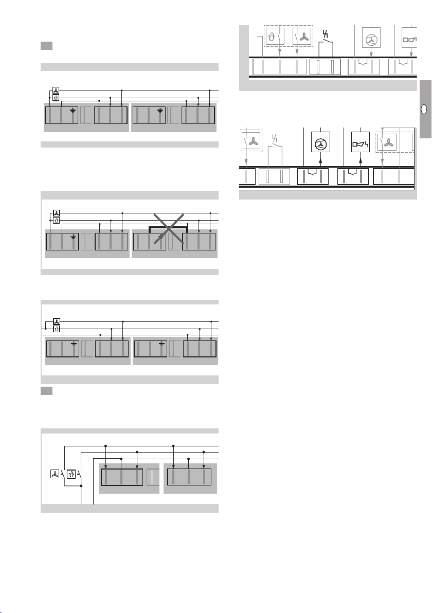
Connection diagram
▷ The burner control unit is fitted with coded con-
nectors to prevent them being mixed up.
LN LN NLT LV +T –+VmA V12
LLiN 12 +
0 V
D – 49018 Osnabrück, Germany
ACU
Connecting the room thermostat
CAUTION
To avoid damage to the heater, please observe
the following:
– Provide post-cooling for the heater. The heater
requires a continuous supply of 230 VAC,
50Hz.
– In case of a power failure, an emergency power
supply unit should automatically take over the
power supply. Emergency power supply units
with a cardan shaft drive for tractor attachment
are also suitable.
▷
Use a room thermostat with a hysteresis of ±1°C.
It switches on if the room temperature is 1°C
less than the set temperature and switches off
again once the room temperature is 1°C more
than the set temperature.
▷ The floating connectors X4 (230V) or X8 (24V)
are used to connect the room thermostat.
▷
If the room thermostat is connected to the mains
supply of other connectors (connector X1 orX3),
the heater will be damaged.
Connecting a single heater to a room
thermostat
5 Connect a room thermostat for 230VAC.
▷ 1. Power supply via the heater.
230 V AC
230 V AC
+V – +T
X8
mV
10-24 V AC/DC
X2
230 V AC
L
N
L N
X1 Gas
NLT LV
X4
X2
L N
X1 Gas
NLT LV
X4
X2
L N
X1 Gas
NLT LV
X4
▷
2. Power supply via the environmental control
computer.
230 V AC
230 V AC
+V – +T
X8
mV
10-24 V AC/DC
X2
230 V AC
L
N
L N
X1 Gas
NLT LV
X4
X2
L N
X1 Gas
NLT LV
X4
X2
L N
X1 Gas
NLT LV
X4
5 Connect a room thermostat for 24VDC/AC to
connectorX8.
▷ The 24V power supply must always be from an
external source.
230 V AC
230 V AC
+V – +T
X8
mV
10-24 V AC/DC
X2
230 V AC
L
N
L N
X1 Gas
NLT LV
X4
X2
L N
X1 Gas
NLT LV
X4
X2
L N
X1 Gas
NLT LV
X4
eBus
Burner Chip
Card (BCC)
Potentiom-
eter
(switch-on
delay)
MFA 2
MFA 1
Remote
reset
0 – 10 V
0 – 20 mA
10 – 24 V
Thermostat
Controlled air
flow
230 V
Thermostat
Controlled
air flow
Mains con-
nection
Mains filter
Mains filter
Mains con-
nection
GB-5
D
GB
NL
RUS
PL
F
E
UA
CN
Connecting multiple heaters to a room
thermostat or an environmental control
computer
5 Connect a room thermostat for 230VAC.
▷ 1. Power supply via the heater.
GP 2
X2
GP 2
– +T
X8
+V
L N
X1 Gas
NLT LV
X4
GP 2
X2
L N
X1 Gas
NLT LV
X4
GP 2
X2
L N
X1 Gas
NLT LV
X4
GP 1
GP 1
GP 1
GP 1
230 V AC
230 V AC
+V – +T
X8
mV
10-24 V AC/DC
X2
230 V AC
L
N
L N
X1 Gas
NLT LV
X4
X2
L N
X1 Gas
NLT LV
X4
X2
L N
X1 Gas
NLT LV
X4
▷ Only one bridge may be connected in a single
heater between connectors X1 andX4. “N” may
be connected to all successive heaters between
connectorsX4 only.
GP 2
X2
GP 2
– +T
X8
+V
L N
X1 Gas
NLT LV
X4
GP 2
X2
L N
X1 Gas
NLT LV
X4
GP 2
X2
L N
X1 Gas
NLT LV
X4
GP 1
GP 1
GP 1
GP 1
230 V AC
230 V AC
+V – +T
X8
mV
10-24 V AC/DC
X2
230 V AC
L
N
L N
X1 Gas
NLT LV
X4
X2
L N
X1 Gas
NLT LV
X4
X2
L N
X1 Gas
NLT LV
X4
▷
2. Power supply via the environmental control
computer.
GP 2
X2
GP 2
– +T
X8
+V
L N
X1 Gas
NLT LV
X4
GP 2
X2
L N
X1 Gas
NLT LV
X4
GP 2
X2
L N
X1 Gas
NLT LV
X4
GP 1
GP 1
GP 1
GP 1
230 V AC
230 V AC
+V – +T
X8
mV
10-24 V AC/DC
X2
230 V AC
L
N
L N
X1 Gas
NLT LV
X4
X2
L N
X1 Gas
NLT LV
X4
X2
L N
X1 Gas
NLT LV
X4
5 Connect a room thermostat for 24VDC/AC to
connectorX8.
▷
The 24 V power supply must be from an external
source.
GP 2
X2
GP 2
– +T
X8
+V
L N
X1 Gas
NLT LV
X4
GP 2
X2
L N
X1 Gas
NLT LV
X4
GP 2
X2
L N
X1 Gas
NLT LV
X4
GP 1
GP 1
GP 1
GP 1
230 V AC
230 V AC
+V – +T
X8
mV
10-24 V AC/DC
X2
230 V AC
L
N
L N
X1 Gas
NLT LV
X4
X2
L N
X1 Gas
NLT LV
X4
X2
L N
X1 Gas
NLT LV
X4
Remote reset
L
N
Reset
MFA
1M
FA
2
max. 5 A
max. 264 V
max. 2 A
max. 264 V
NLT LV
X4
12
X6X5
Li
12
X7
▷ An external remote reset may be connected to
connectorX5.
Multi-functional outputs (MFA)
Reset
MFA 1MFA 2
max. 5 A
max. 264 V
max. 2 A
max. 264 V
AC/DC
10-24 V
LV +V –
+
X8
12
X6X5
Li 12
X7
0 V
▷ Floating multi-functional outputs can be param-
eterized using connectors X6 andX7. There are
two methods of completing this parameteriza-
tion:
The PC software for burner control units BCSoft
can be used via the optical interface on the burn-
er control unit, see page20 (Accessories).
The “Setting mode” menu can be opened us-
ing the MODE selection button (heater OFF)
and used for parameterizing the outputs, see
page8 (Setting mode).
▷ MFA , external fan (max. 5 A)
For improved air circulation in the room, an addi-
tional fan can be connected. The external fan can
be actuated with an adjustable delay (BCSoft) for
switching it on and off. The exact time relates to
the operation of the integrated fan.
▷ Possible parameterization options:
– Inactive: the external fan is not actuated.
– Integrated fan active: the external fan is actuated
at the same time as the integrated fan.
– Integrated fan inactive: the external fan is ac-
tuated when the integrated fan of the heater
switches off.
– Modulation enable: the external fan is not actu-
ated until the heater starts modulating operation.

GB-6
D
GB
NL
RUS
PL
F
E
UA
CN
▷ MFA , status signal (max. 2A)
Possible parameterization options:
– Fault NO (default setting):
For example, the input for a horn can be set to
NO.
– Fault NC:
The input on an environmental control computer
can be set to NC (e.g. to indicate a cable dis-
continuity).
– Operation
– Standby
Burner Chip Card (BCC)
▷
All the data relevant to the device are saved
on the BCC and the internal device memory
(EEProm). In addition, the parameters are saved
on the BCC.
WARNING
Danger of electric shocks!
– Before working on possible live components,
ensure the unit is disconnected from the power
supply.
– If the BCC is removed from the burner control
unit, the heater will be non-functional.
▷ In the event of faults which cannot be rectified
by authorized trained personnel, contact the
supplier.
▷
The BCC can be removed from the burner control
unit and submitted for diagnostic purposes by
agreement with the supplier.
B
CC
+
Delay
▷ If no other fault is active, the heater can be read-
ied for use again by inserting a new BCC. The
BCC must be compatible with the heater, the
version and the gas type used.
Setting the switch-on delay
▷
If multiple heaters switch on at the same time,
there can be a gas and/or power shortage on
individual devices. To avoid this happening, ad-
just the switch-on delay using the potentiometer
on the burner control unit.
▷ The potentiometer is set to 0s at the factory.
– +
▷ If necessary, a switch-on delay of 5 to 10s can
be set between the devices.
6 After completing the wiring, close the cover
and the housing cover on the burner control
unit again.
7 Switch on the power supply.
▷
If a switch-on delay has been programmed, a
circulating dash will be displayed when the volt-
age supply is switched on to indicate that the
switch-on delay is running.
8 Release the gas supply.
9 Commission the heater.
Commissioning
WARNING
To avoid damage to the heater, please observe
the following:
– Ensure that the heater, gas pipes, mains voltage
supply and room thermostat have been installed
by authorized trained personnel according to
the regulations.
– The Burner Chip Card (BCC) must be compat-
ible with the heater, the version, the gas type
used and the factory default parameters.
– The heater may only be operated with the gas
type specified on the type label.
– If the device needs to be converted to be oper-
ated with a different gas type:
1. Use the correct nozzle, see page22 (Spare
parts).
2. Set the appropriate pressure on the burner,
see table on page8 (Adjusting the heater),
and then seal the gas pressure setting.

GB-7
D
GB
NL
RUS
PL
F
E
UA
CN
ACU control panel
MODE RESET ON/OFF
MODE RESET ON/OFF
MODE RESET ON/OFF 1
3
5
7
4
2
6
ON/OFF
OFF 1
2
3
4
5
AUTO
+AUT
MODE
(RESET)
ON/OFF
O
LEDs
MODE selection button
4RESET button
5Status indicator light
6Optical interface
77-segment display
Description of function
ON/OFF
OFF 1
2
3
4
5
AUTO
+AUT
MODE
(RESET)
ON/OFF
O
:
To switch the heater on and off
LEDs:
To indicate the chosen operating mode
Operating
mode Explanation
The burner control unit waits for the
signals for controlled air flow or heating
(automatic)
Continuous heating
(manual)
Controlled air flow in continuous op-
eration
(manual)
Controlled air flow in continuous op-
eration and heating when a thermostat
signal is applied
(automatic)
MODE selection button:
Setting mode can be accessed by pressing and
holding the MODE selection button when the
heater is switched off, see page8 (Setting
mode). The multi-functional outputs can be as-
signed and the eBus address specified in this
mode.
4RESET button:
To reset the device after the occurrence of a fault
5Status indicator light:
red: fault
yellow: standby/ready for operation
green: in operation
6Optical interface:
The PC software BCSoft can be used with the PC
opto-adapter via this interface, see page20
(Accessories).
77-segment display:
To display error codes, the flame signal or the
number of operating cycles. The decimal point
indicates that another figure follows.
Error code
RESET button
Flame signal
Operating cycles
> 3 s RESET button
ON
Error code: an error is displayed immediately
in the form of an alternating letter and number
indicating a warning or fault, see page12 (As-
sistance in the event of malfunction).
Flame signal: pressing the RESET button displays
the flame signal, see page9 (Flame signal).
Operating cycles: press and hold the RESET
button for more than 3s to show the number
of operating cycles in changing displays, see
page18 (Maintenance).
▷
Press the RESET button to exit the display of
the flame signal or operating cycles.
Switching on
• Press ON/OFF
OFF 1
2
3
4
5
AUTO
+AUT
MODE
(RESET)
ON/OFF
O
.
▷
The LED for the last selected operating mode will
flash. A different operating mode can be selected
within 2s. If you retain the selection, the flash-
ing light will change to permanently lit after 2s.
▷ The heater will start once the thermostat signal
has been applied and the set switch-on delay
elapsed, see page6 (Setting the switch-on
delay).
▷
The burner starts up and operates in the last
selected operating mode.
Switching off
• Press ON/OFF
OFF 1
2
3
4
5
AUTO
+AUT
MODE
(RESET)
ON/OFF
O
.
▷
The burner control unit display and the burner
will switch off immediately. Mains voltage is still
supplied however. The display indicates “–”.
▷
The main fan cools the heater down until it
reaches switch-off temperature.
CAUTION
– Do not disconnect the heater from the electrical
power supply until the post-cooling process has
been completed.
▷ The display “–” will go out.
GB-8
D
GB
NL
RUS
PL
F
E
UA
CN
Setting mode
▷
Press and hold the MODE selection button when
the heater is switched off to go to Setting mode.
• Switch off the heater
OFF 1
2
3
4
5
AUTO
+AUT
MODE
(RESET)
ON/OFF
O
.
▷ Mode E: eBus addresses can be saved.
Mode A/F: multi-functional outputs can be pa-
rameterized.
MFA 2 MFA 1
eBus address
Mode E
Mode A/F
MODE
button
MODE
button
MODE
button
MODE
button
eBus adddress 1 ... eBus address 8
Save eBus address
0 Inactive
1 Fault (NC)
2 Fault (NO)
3 Operation
4 Standby
0Inactive
1 Main fan
active
2 Main fan
inactive
3 Modulation
enable
> 2 s MODE button
> 2 s MODE button
> 2 s MODE button
> 2 s MODE button
> 2 s MODE button
> 2 s MODE button
> 2 s MODE button
OFF
▷
Press the RESET button to return to the previ-
ous menu.
▷
After a timeout of 20s, the display will auto-
matically return to the initial mode. The display
indicates “–”.
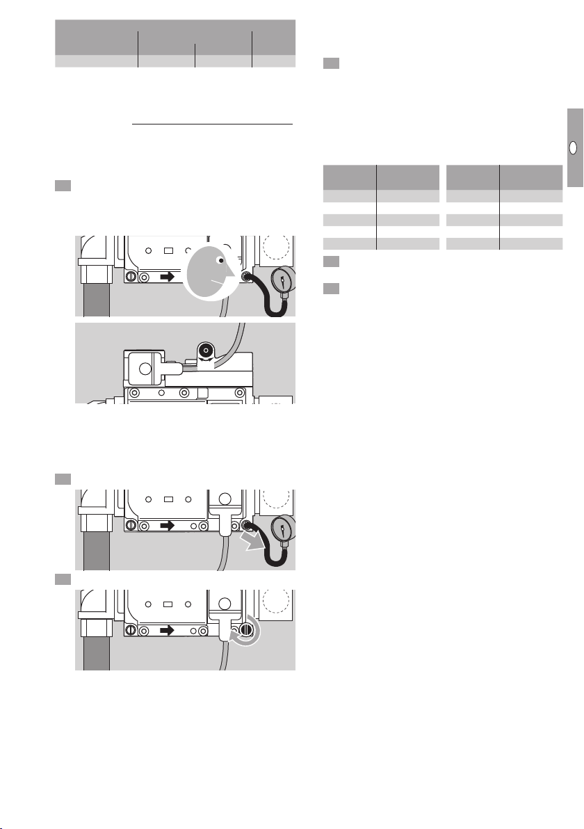
Adjusting the heater
Burner gas pressure pG
pu= Inlet pressure
pG= Gas pressure on the burner
▷
The gas pressure on the burner is adjusted using
pGon the combination control.
+ -
+
-
pupG
▷ For this, the outlet pressurepGmust be meas-
ured on the combination control.
Disconnect the system from the electrical power
supply. The mains plug may only be pulled out
once the device has been switched off and post-
cooling is complete.
Shut off the gas supply.
Open pressure test point pG.
+ -
+
-pG
+ -
+
-
0
p
G
4 Switch on the power supply.
5 Release the gas supply.
▷
The inlet pressurep
u
must comply with the tech-
nical data, see page23 (Technical data).
6 Switch on the burner control unit. Press the
ON/OFF button
OFF 1
2
3
4
5
AUTO
+ AUT
MODE
(RESET)
ON/OFF
O
until an LED lights up.
7 Select the Heating2operating mode.
8 Let all heaters burn for at least 20s.
▷
The required gas pressure on the burner depends
on the heating value/Wobbe index.
9 Select the required gas pressure on the burner
from the tables:
Natural gas, LPG
Gas type
Heating
value
Wobbe
index [mbar]
[MJ/m3]
Natural gas L G25 32.49 41.53 13.5
Natural gas H G20 37.78 50.71 9.5
LPG G 30 125.81 87.34 19.5
GB-9
D
GB
NL
RUS
PL
F
E
UA
CN
G+ K gas*
Gas type Wobbe index [MJ/m3][mbar]
min. max.
G+ K gas 43.46 45.3 13.5
* see page23 (The Netherlands)
▷
Converting the heating value/Wobbe index to
kWh/m3:
kWh/m3=
Heating value/Wobbe index [MJ/m3]
3.6
▷
Always use a pressure gauge to adjust the burner
gas pressure. The white scale on the adjusting
screw may differ.
0 If all heaters are heating at the same time, com-
pare the required gas pressure on the burner
with the gas pressurepGread off the pressure
gauge, adjust it and monitor the pressure gauge.
+ -
+
-
0
pG
+ -
+
-
pG
+ -
+-
▷ The flame must be blue and must remain inside
the device.
▷
Check and adjust the burner pressurep
G
and
flame signal on all devices so that the system
operates correctly.
Remove the pressure gauge from the test point.
+ -
+
-
0
pG
Close the pressure test point.
+ -
+
-pG
Flame signal
▷
The flame signal can be displayed while the
burner is operating.
Press the RESET button to display the flame
signal.
▷
The flame signal is shown in coded form as a
number from 0 to9.
This number must be multiplied by a factor of2.
The result of this multiplication is the level of the
flame signal inµA. Example: the number 3 cor-
responds to a flame signal of 6–8µA.
Display Flame
current [µA] Display Flame
current [µA]
00 – 2 510 – 12
12 – 4 612 – 14
24 – 6 714 – 16
36 – 8 816 – 18
48 – 10 918...
Check the flame signal.
▷ The flame signal is displayed for 20s.
Press the RESET button to exit the flame signal
display.

GB-10
D
GB
NL
RUS
PL
F
E
UA
CN
Cleaning
CAUTION
To ensure that no damage occurs during operation
and cleaning, please observe the following instruc-
tions. Otherwise, injuries or damage to the device
may occur and/or the function of the device may
be impaired, and the manufacturer’s warranty will
be cancelled.
– Sharp-edged metal sheets. Always wear protec-
tive gloves.
– After cleaning, check that the components on
and in the heater are in good condition. The
device may only be restarted if all safety devices
have been installed and the safety functions
have been checked.
– Clean the heater once a year when used in
horticulture and at regular intervals as well as
after each fattening period when used in ag-
riculture, as described below. Inadequate or
irregular cleaning can cause damage to the
device or lead to fire damage. For example, dirt
particles can catch fire and can be blown out
of the heater.
Switch off the burner control unit ACU.
Disconnect the system from the electrical power
supply.
▷ The mains plug may only be pulled out once the
device has been switched off and post-cooling
is complete.
Shut off the gas supply.
4 Check the cover on the burner control unit and
the housing cover to ensure they are both tightly
closed.
▷
The GP is made of high-quality stainless steel
and is resistant to external influences such as
dirt and moisture.
▷
The GP can be cleaned carefully both inside and
outside with a high-pressure cleaner.
▷
The water jet from the high-pressure cleaner can
cause serious damage to the heater compo-
nents. For example, the blade can be bent or
other parts such as the spark plug or rubber
seals can be displaced. Avoid direct contact.
▷ Do not direct the water jet straight at electrical
components such as the vane.
▷
Do not spray water or chemical cleaning agents
directly into the space between the fan shaft/
impeller wheel and motor. Do not clean the fan
shaft/impeller wheel with a high-pressure cleaner.
▷
The housing cover and cable glands on the ACU
must be closed during the cleaning process.
▷
The electrical components are protected from
moisture by additional water drip edges on the
housing cover. Direct water influence on the
edges of the housing cover should be avoided.
▷
A downward slope inside the device ensures
that dirty water drains out.
▷
Never direct the nozzle of the high-pressure
cleaner at the heater when the cleaner is set to
“water jet”. Always use the spray setting.
▷
The distance between the nozzle and the surface
to be cleaned must be at least 50cm. Placing
the high-pressure cleaner at too short a distance
can cause serious damage to the device.
> 50 cm
▷
To facilitate cleaning of the components inside the
housing, the maintenance cover on the casing
can be opened.
56
7 Clean the grille from the outside using a cloth.
▷ Clean the fan, vane and plates for the air intake
using a cloth only.
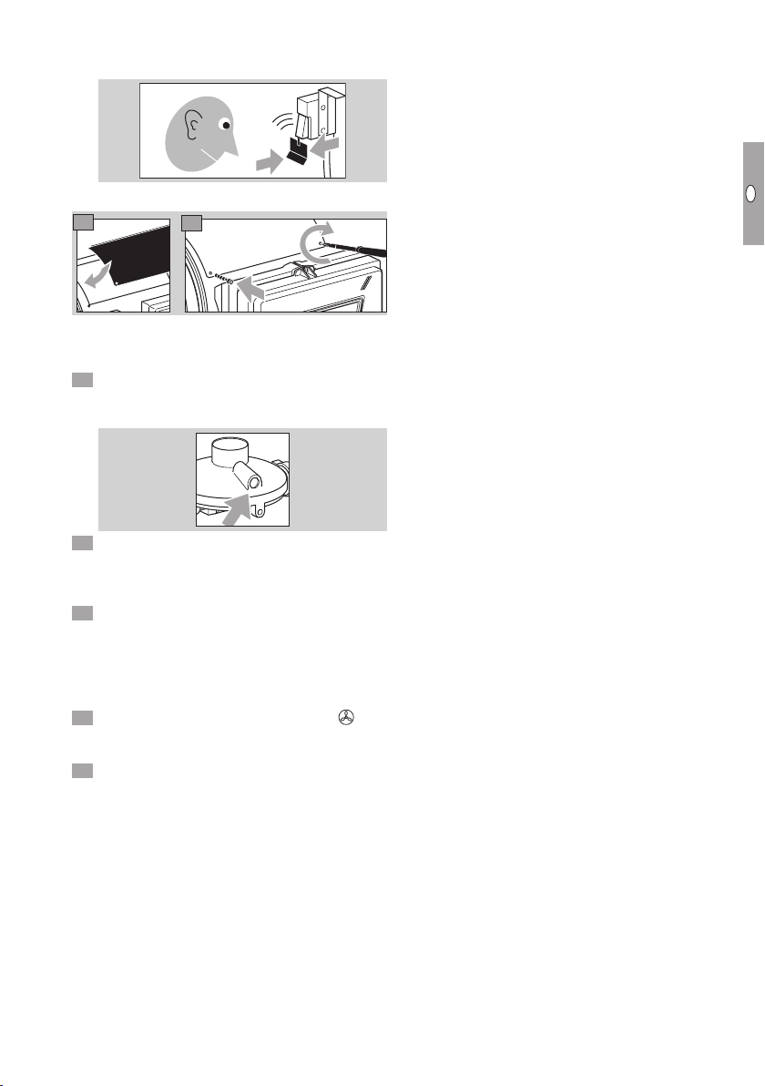
8 9 10
Clean the interior of the device carefully using air.
▷ The vane must not be bent.
Check that the vane switch is functional.
GB-11
D
GB
NL
RUS
PL
F
E
UA
CN
▷
If the vane is moved a little in the direction of the
arrow, a quiet click can be heard. This means
that the switching path is correct.
klick
Assembly
14
13
▷
Check the burner is functioning faultlessly in nor-
mal operation, see page 20 (Checking the
safety functions and burner operation).
5 When operating with propane, check that the
breather orifice of the pressure reducer on the
connection kit is clean.
6 After cleaning, check that all the parts on and
in the heater are in the correct positions, for ex-
ample whether the rubber seals between the
electrodes and terminal boots are fitted correctly.
7 Chemical cleaning agents, disinfectants and/or
pesticides contain corrosive substances which
can even corrode stainless steel. Always rinse
the devices with water after cleaning using such
agents to remove any residue of these agents
from the surface.
8 After cleaning, select operating mode 3Con-
trolled air flow so that the interior of the device
can dry properly.
9 After cleaning the heater, check it is functioning
faultlessly in normal operation, see page20
(Checking the safety functions and burner opera-
tion).
GB-12
D
GB
NL
RUS
PL
F
E
UA
CN
Assistance in the event of
malfunction
WARNING
To avoid harm to persons and animals or damage
to the heater, please observe the following:
– Electric shocks can be fatal! Before working
on possible live components, ensure the unit
is disconnected from the power supply.
– Fault-clearance must only be undertaken by
authorized trained personnel!
– Repairs to components, e.g. the burner control
unit ACU or the combination control CG, may
only be carried out by the manufacturer. Other-
wise, the guarantee will be cancelled. Unauthor-
ized repairs or incorrect electrical connections,
e.g. the connection of power to outputs, can
cause gas valves to open and the burner control
unit to become defective. In this case, fail-safe
operation can no longer be guaranteed.
– (Remote) resets may only be conducted by
authorized trained personnel with continuous
monitoring of the devices concerned.
▷
In the event of an installation fault, the burner
control unit closes the gas valves and the status
indicator light will be red at the latest after a
restart has been unsuccessful.
▷ The 7-segment display will show an error code
in the form of a letter with a decimal point and
a number alternately indicating a warning. To-
gether with the red status indicator light, this
then constitutes a fault.
▷ Warnings and faults may be cleared only using
the remedies described below.
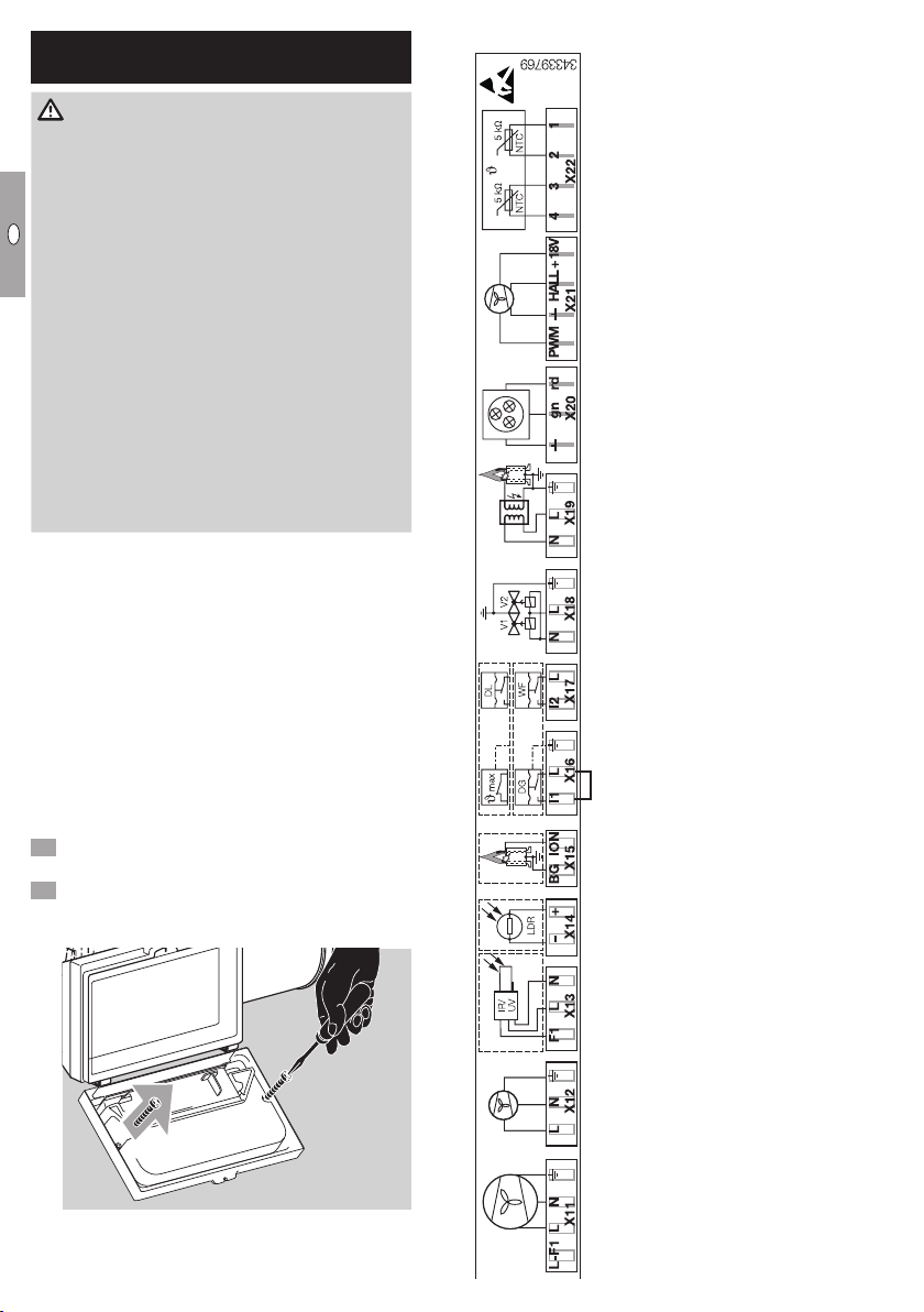
Internal wiring
▷
To rectify a fault, it is sometimes necessary to
check the internal wiring.
Open the housing cover of the burner control
unit.
Undo the two screws (M3) using a Phillips screw
-
driver and remove the complete plastic cover
from the burner control unit.
Internal connection diagram
LN LN NLT LV +T –+VmA V12
LLiN 12 +
0 V
D – 49018 Osnabrück, Germany
ACU
Main fan
Not used
Not used
Not used
Ionization
Gas pressure switch
Vane
Valves
Ignition
Not used
Not used
Safety temperature limiter (STL)

GB-13
D
GB
NL
RUS
PL
F
E
UA
CN
Press the RESET button to reset. The unit then
reverts to the last operating mode selected.
▷ Possible faults:
Display Fault type
FFlame fault
AAir fault
CTemperature fault
EElectronics fault
UOther possible faults
PGas-related faults
4 If the burner control unit does not respond even
though all the possible faults have been rectified
as described below, contact your supplier.
? Fault
! Cause
• Remedy
? The 7-segment display has gone out despite
the voltage supply being OK?
! Fuse F2 is defective.
• Check the fuse contacts.
There is a spare fuse directly next to the fuse
holder.
Attention! Fit the correct fuse for 4A.
LN LN NLT LV +T –+VmA V12
LLiN 12 +
0 V
D – 49018 Osnabrück, Germany
ACU
? Error code P. and 1flash alternately and the
light is red?
! Pressure switch does not switch.
• Check inlet pressure pu.
! Gas pressure on the burner too low.
• Readjust gas pressurep
G
on the combination
control, see page8 (Adjusting the heater).
! Fuse F2 defective.
• Replace fuse (3.15 A, slow-acting, H). Ensure
that only one heater is directly wired to the ther-
mostat, see page3 (Wiring).
? Error code P. and 2flash alternately and the
light is red?
! During three consecutive restarts, the gas pres-
sure switch has tripped during the safety time
or flame proving period (gas pressure switch
oscillates).
• Inlet pressure fluctuates. Establish stable gas
supply.
• Gas pressure pGtoo low. Readjust gas pres-
surepG, see page8 (Adjusting the heater).
? Error code A. and 1flash alternately?
! Vane switch switches off during burner operation.
• Check the function of the vane switch, see
page18 (Maintenance).
• Vane, fan or grille are dirty. Clean, see page18
(Maintenance).
• Fuse F1 defective (8 A, slow-acting, H). Check
the function of the fan and replace fuseF1 if
necessary.
! Motor defective.
• Remove the device and return it to the supplier.
? Error code A. and 2flash alternately?
! Vane switch does not switch off during the “no
flow” state check on burner start-up.
• Check that the vane switch is functional, see
page18 (Maintenance).
? Error code A. and 2flash alternately and the
light is red?
! The fault “Vane switch” could not be rectified.
The programmed number of start-up attempts
having failed, the ACU initiates a fault lock-out.
• Reset using the RESET button on the ACU or
via the remote reset.
• Check that the vane switch is functional, see
page18 (Maintenance).
GB-14
D
GB
NL
RUS
PL
F
E
UA
CN
? Error code A. and 3flash alternately?
! The vane switch has not switched on 15s after
the fan has been switched on.
• Vane, fan or grille are dirty. Clean, see page18
(Maintenance).
• Fuse F1 defective (8 A, slow-acting, H). Check
the function of the fan and replace fuseF1 if
necessary.
! Motor defective.
• Remove the device and return it to the supplier.
? Error code A. and 3flash alternately and the
light is red?
! The fault could not be rectified. The programmed
number of start-up attempts having failed, the
ACU initiates a fault lock-out.
• Reset using the RESET button on the ACU or
via the remote reset.
• Check that the vane switch is functional. Clean
the vane, fan or grille if soiled.
? Error code F. and 1flash alternately?
! On burner start-up, the ACU has not detected
a flame during the safety time. In the parameter
“Number of start-up attempts”, it is possible to
program up to three start-up attempts. If one
of the further start-up attempts is successful,
warning signalling stops automatically once the
post-purge time has elapsed.
! Ignition is not working properly.
• Clean the spark electrode and check for correct
distance, see page18 (Maintenance).
• Check the connection of the ignition cables for
damage or moisture.
▷ The spark plug must be fitted correctly.
• Check the ignition spark optically and acoustically
from the fan side during the 4-second ignition
time.
! Poor flame signal due to incorrect burner adjust-
ment.
• Readjust gas pressurepG, see page 8 (Ad-
justing the heater).
! Poor flame signal due to dirty/badly connected
flame rod.
• Clean the flame rod and check for correct dis-
tance, see page18 (Maintenance).
• Check the cable connection, cable and terminal
boot for damage or moisture. The terminal boot
must be fitted correctly.
• Check the yellow and green burner ground cable
for corrosion and to ensure it is firmly connected.
! Air in the gas pipe.
• Vent the gas pipe.
! Valves do not open.
• Remove the valve plug on the combination con-
trolCG and measure the voltage betweenL1
andN during the safety time. If the voltage is
not adequate, first replace the CG and return it
to the supplier.
Attention! Only commission the new ACU once
the short-circuit or fault on the valve output of
the CG has been remedied. Otherwise, the new
ACU will be damaged.
• If the fault continues to be signalled, there may
be a short-circuit on the valve output. Return
the burner control unit to the manufacturer for
inspection.
! Short-circuit on ignition output.
• Replace fine-wire fuse F2 (3.15A, slow-acting,
H) and check the safety function, see page20
(Checking the safety functions and burner opera-
tion).
? Error code F. and 1flash alternately and the
light is red?
! The fault could not be rectified. The programmed
number of start-up attempts having failed, the
ACU initiates a fault lock-out.
• Reset using the RESET button on the ACU or
via the remote reset.
• Rectify the cause of the fault as described for
warning F.1.
? Error code F. and 2flash alternately?
! The flame has gone out during operation. If a
restart has been programmed, an automatic re-
start is carried out provided that the burner has
been in operation for at least 2s beforehand.
• Poor flame signal due to incorrect burner adjust-
ment. Readjust gas pressurepG, see page8
(Adjusting the heater).
• Poor flame signal due to dirty or badly connected
flame rod. Clean the flame rod and check for
correct distance, see page18 (Maintenance).
• Check the cable connection for damage or mois-
ture. The terminal boot must be fitted correctly.
GB-15
D
GB
NL
RUS
PL
F
E
UA
CN
• Check the yellow and green burner ground cable
for corrosion and to ensure it is firmly connected.
? Error code F. and 2flash alternately and the
light is red?
! The fault could not be rectified. The programmed
number of start-up attempts having failed, the
ACU initiates a fault lock-out.
• Reset using the RESET button on the ACU or
via the remote reset.
• Rectify the cause of the fault as described for
warning F.2.
? Error code F. and 3flash alternately and the
light is red?
! The burner control unit detects a flame signal
during start-up or in fault status.
! A gas valve does not close correctly.
• Shut off the gas supply to the device. Check the
burner and gas valves for correct function, see
page20 (Checking the safety functions and
burner operation).
! Incorrect flame signal due to leakage/creepage
current.
• Check wiring, see page3 (Wiring).
• Check the flame rod.
! Incorrect flame signal through conductive ce-
ramic insulation, e.g. surge via PE wire, possible.
• Remedy incorrect flame signal. Replace the flame
rod and, if necessary, also the complete burner
control unit and housing.
▷
Reset is only possible by pressing the RESET
button on the burner control unit or using the
remote reset if there is one.
? Error code F. and 4flash alternately and the
light is red?
! The flame has not gone out within 5s of the
burner being switched off. A gas valve does not
close correctly.
• Shut off the gas supply to the device. Check the
burner and gas valves for correct function, see
page20 (Checking the safety functions and
burner operation).
? Error code C. and 1flash alternately and the
light is red after 5minutes?
! Signal from safety temperature monitor (STM).
Temperature has been exceeded.
• Leave heater to cool down for longer.
! The main fan does not switch on.
• Check the main fan.
! Wiring fault.
• Check the wiring to actuate the main fan, see
page3 (Wiring).
! The safety temperature monitor (STM) is incor-
rectly aligned.
• Check the position of the safety temperature
monitor(STM).
! Ambient temperature exceeded.
• The temperature is >40°C. Allow the room to
cool.
! The safety temperature monitor (STM) is measur-
ing an incorrect temperature.
• Replace the safety temperature monitor.
! The heater is badly soiled.
• The heater must be cleaned urgently.
! Installation position.
• The heater is too close to other heaters, see
page2 (Installation).
! Device incorrectly set.
• The heater is not set correctly and must be ad-
justed, see page8 (Adjusting the heater).
! In the event of a power failure during operation,
the heater will be switched off without a cool-
ing phase. If the power failure lasts less than
5minutes, the combustion chamber will heat
the device and the STL will issue a signal.
• In this case, Controlled air flow mode is activated.
If the heater has been successfully cooled within
1minute, it will restart.
? Error code C. and 2flash alternately and the
light is red?
! Signal from safety temperature limiter (STL).
Temperature has been exceeded.
! The cause of the fault as described above for
faultC.1 could not be rectified.
• Check the heater for damage, see page18
(Maintenance).

GB-16
D
GB
NL
RUS
PL
F
E
UA
CN
? Error code C. and 9flash alternately and the
light is red?
! Temperature sensor incorrectly connected.
• Check contact at connector X22.
! Temperature sensor is below -30°C.
! Temperature sensor defective.
• Replace temperature sensor.
! Incorrect temperature sensor.
▷ Sensor BCU is not compatible with the ACU.
• Select the correct temperature sensor for the
ACU.
? Error code E. and 1flash alternately?
! The remote reset input is defective.
• If you use the remote reset input, contact your
supplier.
? Error code E. and 2flash alternately and the
light is red?
! An adjustable parameter and the CRC check are
not the same. The parameters are implausible.
• Order a new BCC. Contact your supplier.
▷
Reset is only possible by pressing the RESET
button on the burner control unit or using the
remote reset if there is one.
? Error code E. and 3flash alternately and the
light is red?
! A fixed parameter and the CRC check are not
the same. The parameters are implausible.
• Order a new BCC. Contact your supplier.
▷
Reset is only possible by pressing the RESET
button on the burner control unit or using the
remote reset if there is one.
? Error code E. and 4flash alternately and the
light is red?
! Limits for fixed parameters not observed.
• Order a new BCC. Contact your supplier.
? Error code E. and 5flash alternately and the
light is red?
! The BCC is not connected.
• Connect the BCC to the printed circuit board.
? Error code E. and 6flash alternately and the
light is red?
! An incorrect BCC is connected. The BCC must
be compatible with the GP.
• Remove the BCC and connect the correct BCC
to the printed circuit board, see page6 (Burn-
er Chip Card (BCC)).
? Error code E. and 8flash alternately?
! Programming mode is active.
• As soon as Programming mode has been de-
activated, the display will go out.
? Error code E. and 9flash alternately?
! Internal electronics fault.
• Remove the BCC and return it to the supplier.
? Error code U. and 1 flash alternately and the
light is red?
! Voltage supply is below the limit (programmable
limit, e.g. <160V).
• Ensure that adequate mains voltage is supplied.

GB-17
D
GB
NL
RUS
PL
F
E
UA
CN
? Error code U. and 2flash alternately and the
light is red?
! Voltage supply is above the limit (programmable,
e.g. >260V).
• Ensure that adequate mains voltage is supplied.
? Error code U. and 3flash alternately and the
light is red?
! All start-up attempts in the programmed voltage
range (e.g. 160–180V) were unsuccessful. The
last start-up attempt is not made to prevent a
lock-out.
• Ensure that adequate mains voltage is supplied.
? Error code U. and 5flash alternately and the
light is red?
! While a fault was pending, the unit has been
successfully reset more than 5 times within
15minutes using the remote reset input.
▷
Reset is only possible by pressing the RESET
button on the burner control unit or using the
remote reset if there is one.
? Error code U. and 6flash alternately and the
light is red?
! The unit has been unsuccessfully reset more
than 10times within 15minutes using the remote
reset input.
▷
Reset is only possible by pressing the RESET
button on the burner control unit or using the
remote reset if there is one.
? A circulating dash is displayed rather than
an error code?
▷
After switching on the voltage, a circulating dash
is displayed.
! Switch-on delay time running.
Or
! Cycle lock active. The time (cycle lock) between
two starts is too short.
▷ The display will go out automatically as soon as
the time between two starts is long enough. The
burner control unit will ensure a pause between
start-up attempts on the basis of its parameteri-
zation. This warning is displayed during this time.
Or
! The pressure switch signal does not drop when
the main fan is switched off.
▷ A burner restart is not possible.
▷ After 25s, the display will change to error code
A. 9.

GB-18
D
GB
NL
RUS
PL
F
E
UA
CN
Maintenance
CAUTION
To ensure that no damage occurs during operation
and maintenance, please observe the following
instructions. Otherwise, injuries or damage to the
device may occur and/or the function of the device
may be impaired. The supplier/manufacturer cannot
accept liability for damage resulting thereof.
– Have the heater cleaned at least once a year
by qualified maintenance personnel.
– Have the safety functions checked at least once
a year by qualified maintenance personnel, see
page20 (Checking the safety functions and
burner operation).
– Sharp-edged metal sheets. Always wear protec-
tive gloves.
– After cleaning or repair work, check that the
components on and in the heater are in good
condition. The device may only be restarted
if all safety devices have been installed and
the safety functions have been checked, see
page20 (Checking the safety functions and
burner operation).
Switch off the burner control unit ACU.
Disconnect the system from the electrical power
supply.
▷ The mains plug may only be pulled out once the
device has been switched off and post-cooling
is complete.
Shut off the gas supply.
▷
To facilitate cleaning of the components inside
the housing, the service cover on the casing
can be opened.
45
▷ Alternatively, the fan may be removed.
7
68
10
911
Clean the grille with a cloth.
Clean the interior of the device carefully using air.
▷ The vane must not be bent.
4 Clean the fan and vane using a cloth.
5 Check that the vane switch is functional.
▷
If the vane is moved a little in the direction of the
arrow, a quiet click can be heard. This means
that the switching path is correct.
klick
▷ Check the nozzle and burner baffle plate for dirt
and if necessary, clean using a cloth. Remove
first the burner baffle plate, then the nozzle. To
do this, a special tool is required. Nozzle spanner
size = A/F 36 and A/F 46. The nozzle is secured
via the burner baffle plate by a cross-head screw.
17
16
8 Loosen the A/F 36 nut to detach the gas pipe.
Note the seal.
9 Then loosen the A/F 46 nut.
SW 36
SW 46
▷ Remove the nozzle.
20
▷
The flame rod and spark electrode can be re-
moved without having to dismantle the combus-
tion chamber.

GB-19
D
GB
NL
RUS
PL
F
E
UA
CN
Check the nozzle for signs of damage and dirt
and clean if required.
SW 21
SW 22
242322
272625 SW 21
8 Check the electrodes for dirt and if necessary,
clean using a cloth. Remove stubborn dirt on
the electrode rod using fine abrasive paper.
9 Check electrodes and porcelain insulators for
cracks and replace the electrodes in case of
damage.
▷ Replace the electrodes if necessary.
▷ Fit the electrode seal.
0 Clean the plates for the air intake using a cloth.
Assembly
▷ Ensure that the rubber seals between the elec-
trodes and the terminal boots are fitted correctly.
SW 21
SW 22
31
363534
3332
SW 21
▷
Ensure the electrodes are at the correct distance
from one another and correctly positioned as
regards the nozzle.
2 mm
▷
The device may only be restarted if all safety
devices have been installed.
38
37 39
41
40 42
4 Check the safety functions before commission-
ing, see page20 (Checking the safety func-
tions and burner operation).
GB-20
D
GB
NL
RUS
PL
F
E
UA
CN
Checking the safety functions and
burner operation
WARNING
If these checks are not carried out, the gas valves
might remain open allowing non-combusted gas
to escape. Risk of explosion!
Safety functions
Switch off the heater during operation. Press
ON/OFF
OFF 1
2
3
4
5
AUTO
+ AUT
MODE
(RESET)
ON/OFF
O
.
▷ The flame goes out <1s.
▷
The fan cools the heater down until it reaches
switch-off temperature.
Remove the valve plug on the combination con-
trol during operation.
▷ The gas valves close <1s.
▷ The flame goes out.
▷ The burner control unit ACU displays the warn-
ing message “The flame has gone out during
operation”. Error code F. and 2 flash alternately.
▷
If a restart has been programmed, the burner
control unit will initially attempt to restart and
will then perform a fault lock-out. Error code F.
and 1 flash and indicate the fault message “No
flame has been detected during the safety time”.
Shut off the inlet pressure during operation.
▷ The pressure switch in the combination control
switches because the supply pressure is too low.
▷
The burner control unit performs a safety shut-
down: the gas valves are disconnected from the
electrical power supply.
▷ The flame goes out.
▷
The burner control unit ACU displays the fault
message “Supply pressure too low”. Error code
P. and 1 flash alternately and the light is red.
▷ If the burner control unit responds in a different
way to that described, a fault has occurred, see
page12 (Assistance in the event of malfunc-
tion).
CAUTION
The fault must be remedied before the system may
be operated.
Checking burner operation
Switch on the ACU.
Select operating mode2
OFF 1
2
3
4
5
AUTO
+ AUT
MODE
(RESET)
ON/OFF
O
Heating.
Allow the burner to burn for 15minutes.
4 During this time, monitor the flame pattern.
▷ The flame must be blue.
▷ No dirt particles must come out of the heater.
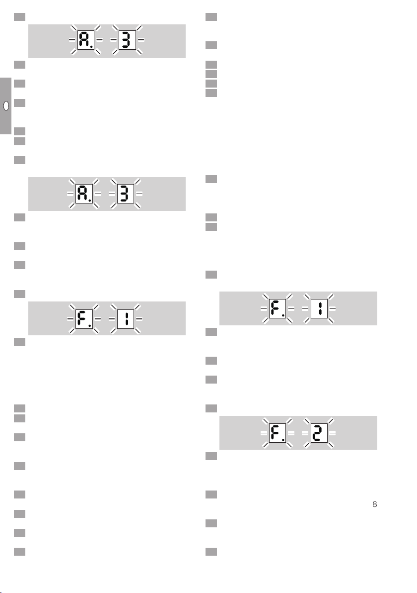
Accessories
Room thermostat
Use a room thermostat with a hysteresis of ±1°C,
230V, Type TH215.
35
30
25
2015
10
5
0
°C
TH215
OrderNo.: N50260145
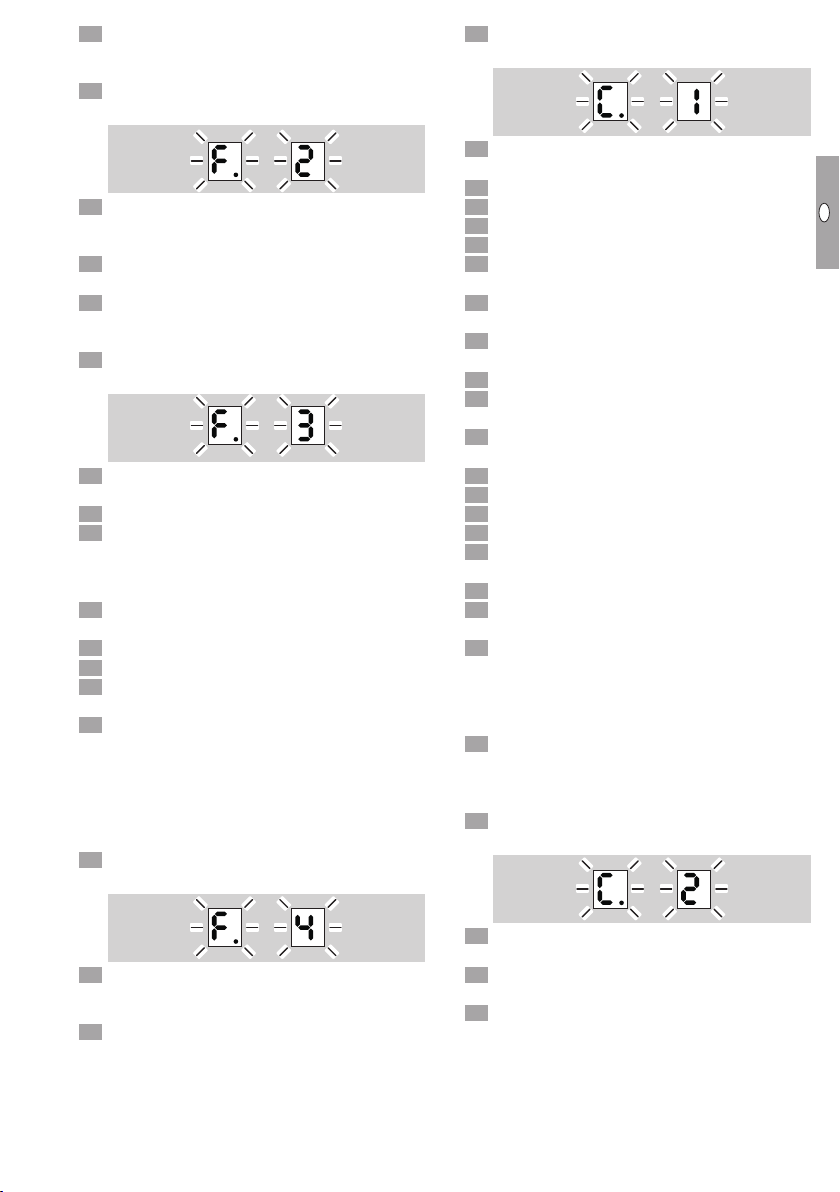
Pressure reducer
Pressure reducer for LPG.
RECA 1.5 bar to 50mbar, 2x½" internal thread
connection, 10kg/h, Order No.: N52600023.
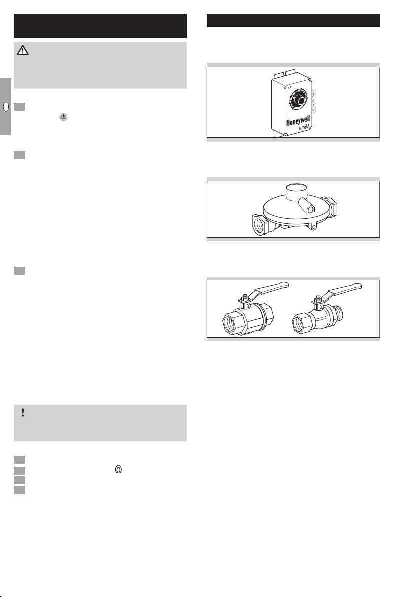
Manual valve
2 x ½"internal thread connection,
Order No.: N52600019.
½"internal and external thread connection,
Order No.: N52600027.
Table of contents
Other ermaf Heater manuals


Popular Heater manuals by other brands


Somogyi Elektronic
Somogyi Elektronic Home FK 130/2000 instruction manual

Heat Storm
Heat Storm Tradesman HS-1500-TT User manual and safety instruction

Jobsite
Jobsite CT2142 Original instructions

De Vielle
De Vielle DEF057232 Installation instructions manual
 Use & care guide")
Kenmore
Kenmore 13477900B (0807) Use & care guide

Jata calor
Jata calor C204NT INTRUCTIONS OF USE


