ermaf GP 120 User manual

© 2013 Elster-Instromet B.V.
➔www.docuthek.com
D GB NL RUSPL F E UA
Safety
Please read and keep in a safe place
Please read through these instructions
carefully before installing or operating. Following the
installation, pass the instructions on to the opera-
tor. This unit must be installed and commissioned
in accordance with the regulations and standards
in force. These instructions can also be found at
www.docuthek.com.
Explanation of symbols
• , , , ... = Action
▷= Instruction
Liability
We will not be held liable for damage resulting
from non-observance of the instructions and non-
compliant use.
Safety instructions
Information that is relevant for safety is indicated in
the instructions as follows:
DANGER
Indicates potentially fatal situations.
WARNING
Indicates possible danger to life and limb.
CAUTION
Indicates possible material damage.
Maintenance and repairs may only be carried out by
qualified gas technicians and electrical interventions
may only be carried out by qualified electricians.
Conversion, spare parts
All technical changes are prohibited. Only use OEM
spare parts.
Transport
On receipt of the product, check that the delivery
is complete (see page 2 (Part designations)). Report
any transport damage immediately.
Storage
Store the product in a dry place. Ambient tempera-
ture: see page 17 (Technical data).
Changes to edition .
The following chapters have been changed:
– Checking the usage
– Installation
– Accessories
– Technical data
– Contact
Contents
Operating instructions
Translation from the German
D
GB
F
NL
I
E
GB-1
0558 Edition 06.
Heater GP 0..........................
Contents ..............................
Safety.................................
Checking the usage .....................
Type code .............................2
Part designations ........................2
Type label..............................2
Installation ............................
Tightness test ..........................
Removing the protective caps (optional)....
Wiring ................................
Connecting the room thermostat for “Heating”
and “Controlled air flow” mode..............4
Connecting multiple heaters to a single
room thermostat ........................5
Reset, alarm, external fan..................5
Adjusting the switch-on delay tE............5
Commissioning.........................6
Adjusting the heater.....................6
Installing the protective caps .............7
Cleaning ..............................8
Assistance in the event of malfunction .....9
Maintenance ..........................
Checking the safety functions and
burner operation ......................4
Accessories ..........................4
Spare parts ...........................6
Technical data ........................7
Declaration of conformity ...............7
Goods return form . . . . . . . . . . . . . . . . . . . . . 8
Contact ..............................8
Heater GP 0
Contents
Safety
GB-2
D
GB
F
NL
I
E
Checking the usage
GP 0
Heater with direct, open combustion for agricultural
stables and horticultural greenhouses. Depending
on the type and setting, the heater can be operated
with natural gas or LPG (propane/butane).
This function is only guaranteed when used within the
specified limits – see page17 (Technical data).
Any other use is considered as non-compliant.
Type code
Code Description
GP Heater
0 Capacity 120kW, jet length 50 m
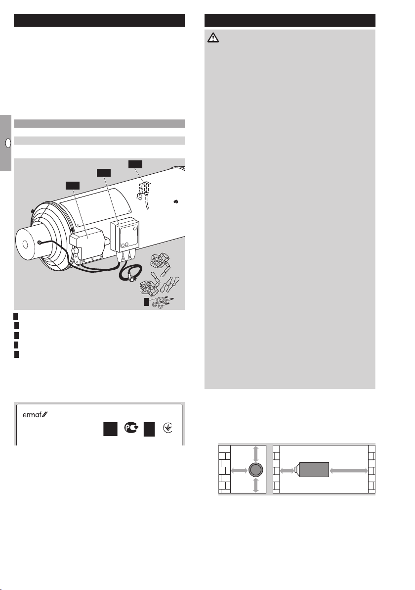
Part designations
4
3, 5
2, 5
1, 5
Burner control unit BCU
Gas combination control CG
Vane
4Assembly accessories
5Protective cap set for use in agriculture (option)
Type label
Air circulation, electrical connection rating, voltage,
rated heat input, gas type, category, supply pressure,
burner pressure, enclosure: see type label.
Elster s.r.o.
Dr. A. Schweitzera 194
SK-91601 Stará Turá
UA.TR012-13AИ 50
● Before installation, check whether the device is
suitable for the regional gas type and the specified
limits, see type code and page 17 (Technical
data).
Installation
DANGER
Danger of death! Gases are generated during the
storage of slurry which remain partly dissolved in
the liquid. If the slurry is strongly agitated during
mixing and purging, poisonous, explosive gases
such as hydrogen sulphide and methane are re-
leased. If an ignition source is present, the released
gas can explode.
To avoid damage during operation, please observe
the following:
– Switch off the heater before mixing and purging
the slurry.
– Close the slide valves when storing slurry out-
side.
– The fan for the air supply must not be part of a
closed pipe system.
– The space to be heated must be adequately
ventilated.
For mechanical extraction equipment: at least
10m3/h of air per installed capacity.
In the case of natural ventilation, the structure
must have two apertures with a free opening
area of 60x B in cm2. “B” is the installed capac-
ity in kW. Replacement of the full air volume per
hour is thus ensured.
– In the case of natural ventilation, the maximum
allowable total capacity of the heater is 1kW
per 20m3of volume.
– Respect the safety distance of the heater to
inflammable materials, see “Installation position”.
– Consult your fire insurance provider and/or local
fire protection engineer to assess the foresee-
able, general risk of fire.
– For cleaning, care and maintenance, note the
applicable national regulations and directives.
– No condensation permitted. Check the ambient
temperature, see page 17 (Technical data).
Installation position
▷ To ensure that the vane functions faultlessly, in-
stall the unit in the horizontal position.
▷
Note the safety distance to walls and inflam-
mable materials.
> 1m
> 0,8m
> 1m
> 3 m> 1m
▷ Ensure sufficient free space around the device.
There must be no obstructions in front of the inlet
and outlet side of the heater.
▷ To avoid overheating, do not cover the electric
motor.

GB-3
D
GB
F
NL
I
E
Connecting the gas supply
▷
If the heater is suspended on chains, use an
approved flexible gas hose.
Disconnect the system from the electrical power
supply.
Shut off the gas supply.
Remove the screw plug at the inlet tube of the
gas combination controlCG.
4 Connect the gas pipe with threaded connection
(Rp¾" internal thread) or gas hose, see page14
(Accessories), to the inlet tube of the gas com-
bination control.
▷ Use approved sealing material only.
▷ Note the maximum inlet pressure, see page17
(Technical data).
Tightness test
▷ The system is disconnected from the electrical
power supply. The valves are thus closed.
N2
= max. 100 mbar
1 2
Removing the protective caps
(optional)
▷ For agricultural use, the burner control unit, gas
combination control and vane switch are mostly
protected against ingress of dirt and moisture
by a cap.
▷ To wire the burner control unit and to start and
adjust the heater, the protective caps are to be
removed as described below.
▷ Do not remove the protective cap on the vane
switch.
Burner control unit
Slowly pull apart the ends of the protective cap
on the back of the burner control unit until the
rivets come undone.
ON/OFF
(RESET)
MODE
OFF
AUTO
+AUTO
Pull the opened edges of the protective cap out
fully so that the edges are pulled out from between
the burner control unit and the mounting plate.
ON/OFF
(RESET)
MODE
OFF
AUTO
+AUTO
Remove the opened protective cap from the
burner control unit by pulling it upwards.
ON/OFF
(RESET)
MODE
OFF
AUTO
+AUTO
Gas combination control
Slowly pull apart the ends of the protective cap
on the underside until all the rivets come undone.
Starting on the right-hand side, pull the opened
protective cap upwards over the gas outlet.
Remove the protective cap completely by pulling
over the left-hand side of the gas inlet.
Wiring
CAUTION
Danger of electric shocks!
– Before working on possible live components,
ensure the unit is disconnected from the power
supply.
Disconnect the system from the electrical power
supply. The mains plug may only be pulled out
once the device has been switched off.
Shut off the gas supply.
▷ If there is a protective cap on the burner control
unit, this must first be removed.
▷ When opening the burner control unit, do not in-
cline the upper housing section during its removal
to prevent the plug connectors from being bent.
4
3

GB-4
D
GB
F
NL
I
E
Burner control unit BCU connection diagram
12345678910111213141516
17 18 19 20 21 22 23 24 25 26 27 28 29 30 31 32
PE
N (L2)
L1 (L1)
F1
F2
V2V1
WF
24 V
0 V
ϑ
ϑ
IZ
PE
BCU 300:THP-G
DG
max. 2 A,
253 V
max. 5 A,
253 V
N
F1 T 8A H
F2 T 3,15A H
IEC 60127-2/5
N
AC/DC
ϑ
35453625
▷ In order to ensure post-cooling, the heater con-
stantly requires 230 V AC.
Connecting the room thermostat for “Heating”
and “Controlled air flow” mode
▷
Use a room thermostat with a hysteresis of ±1°C.
It switches on if the room temperature is 1°C
less than the set temperature and switches off
again once the room temperature is 1°C more
than the set temperature.
▷ Do not directly connect the room thermostat to
terminals1 and3.
5 Connect the terminals for Controlled air flow
ϑ
and Heating
ϑ
.
31 3229 3028
31 3229 3028
0
26 27
28
24 2523
0
26 27
28
24 2523
230 V ~ 230 V ~
+24 V =/~
+24 V =/~
+24 V =/~
+24 V =/~
GB-5
D
GB
F
NL
I
E
Connecting multiple heaters to a single room
thermostat
▷ Phase reversal will result in a short-circuit.
▷ Do not install different phases of a three-phase
current system at the inputs if the voltage be-
tween the phases exceeds 230V (+10%).
▷
Multiple heaters must be wired to the thermostat
via a relay.
29
K3/1
K3
24 V=/230 V~
230 V~
230 V~
230 V~
30
1. GP
29 30
2. GP
29 30
3. GP
K3/2K3/3
▷
At 24VDC/AC, multiple heaters can be con-
trolled in parallel.
▷ Note the polarity!
230 V~
24 V=/~
1. GP
26 2725
2. GP
26 2725 26 2725
3. GP
▷
Do not directly connect the thermostat to mul-
tiple heaters.
▷
Do not connect terminals28, 29 and30 directly
to the next heater. A short-circuit can occur due
to different phases and polarities.
29 30
1. GP
29 30
2. GP
29 30
3. GP
29 30
3. GP
28 29
1. GP
30 28 29
1. GP
30 28 29
1. GP
30 28 29
1. GP
30
Reset, alarm, external fan
▷
For external fault signalling, an external
alarm
ϑ
and an external reset button
ϑ
can be connected.
22 2320 2119
NL1
31 3229 30
28
230 V ~
max. 2 A
230 V ~
6 For improved air circulation in the room, an ad-
ditional fan
ϑ
can be connected.
24 25 2622 2321
NL1
253 V AC
max. 5A
▷ In case of a power failure, an emergency power
supply unit should automatically take over the
power supply. Emergency power supply units
with a cardan shaft drive for tractor attachment
are also suitable.
Adjusting the switch-on delay tE
▷
If multiple heaters switch on at the same time,
there can be a gas and/or power shortage on in-
dividual devices. To avoid this happening, adjust
the switch-on delaytEusing the potentiometer
in the upper housing section of burner control
unitBCU.
▷ The potentiometer is set to 0s at the factory.
tN
tM
0
1
0
2
0
3
0
4
0
5
0
6
0
tE
7
▷ We recommend using a switch-on delaytEof 5
to 10s between each device.
▷
The post-cooling timet
N
is set to 50s at the
factory and the minimum burner on timetMto
0s. These values must not be changed.
▷
Once the wiring is complete, close the BCU
again. Ensure that the upper housing section is
not inclined when being replaced on the lower
housing section.
98
▷
To guarantee that the burner control unit com-
plies with enclosure IP54, make sure that the
screws are tightly secured after wiring and that
the cable glands are closed.
0 Switch on the power supply.
Release the gas supply.

GB-6
D
GB
F
NL
I
E
Commissioning
▷ The heater may only be commissioned once it
has been ensured that the heater, gas pipes,
mains voltage supply and room thermostat have
been installed by authorized, trained personnel
according to the regulations.
Switch on the power supply.
Release the gas supply.
Part designations
ON/OFF (RESET)
MODE
OFF
AUTO
+AUTO
3
4
5
2
1
MODE/RESET selection button
BCU On/Off switch
Red lamp lights up if a fault is pending
4Operating mode LED: Off
5LEDs for selectable operating modes
▷
The BCU is operated using two buttons:
using the ON/OFFbutton
OFF 1
2
3
4
5
AUTO
+ AUT
MODE
(RESET)
ON/OFF
O
, the heater is
switched on and off. By pressing the MODE
selection button for >1s, it is possible to switch
between the different operating modes.
Operating
mode Explanation
OFF 1
2
3
4
5
AUTO
+ AUT
MODE
(RESET)
ON/OFF
O
BCU waits for the signals for controlled
air flow or heating.
OFF 1
2
3
4
5
AUTO
+ AUT
MODE
(RESET)
ON/OFF
O
Heating (continuous operation)
OFF 1
2
3
4
5
AUTO
+ AUT
MODE
(RESET)
ON/OFF
O
Controlled air flow (continuous opera-
tion)
OFF 1
2
3
4
5
AUTO
+ AUT
MODE
(RESET)
ON/OFF
O
Controlled air flow (continuous opera-
tion) and heating when thermostat sig-
nal is applied
Switching on
Switch on the burner control unit. Press ON/OFF
OFF 1
2
3
4
5
AUTO
+ AUT
MODE
(RESET)
ON/OFF
O
until an LED lights up.
▷
The BCU switches on in the last operating mode
selected.
▷ The heater starts once the set switch-on delay
timetEhas elapsed, see page5 (Adjusting the
switch-on delay tE).
▷ The burner starts after the safety time of 5s has
elapsed and operates in the selected operating
mode.
▷ The operating mode can be changed using the
MODE selection button. The selected operating
mode is only activated once the device has been
in this position for at least 3s. It is thus possible
to “scroll” through the different operating modes.
Switching off
4 Switch off the heater. Press ON/OFF
OFF 1
2
3
4
5
AUTO
+ AUT
MODE
(RESET)
ON/OFF
O
. The LED
next to “
OFF 1
2
3
4
5
AUTO
+ AUT
MODE
(RESET)
ON/OFF
O
” lights up and the burner switches off
after 3s. Mains voltage is still supplied however.
▷
The fan cools the heater down until it reaches
switch-off temperature.
Faults
▷
Flashing LEDs signal the cause of a fault, see
page9 (Assistance in the event of malfunction).
▷
In the first 4s after switching on the power supply
or pressing the ON/OFFbutton
OFF 1
2
3
4
5
AUTO
+ AUT
MODE
(RESET)
ON/OFF
O
, an operating
mode is not yet active. Within these 4s, a new
operating mode can be selected. As soon as
the MODE selection button has been pressed
and a new operating mode has been selected,
the 4s are extended accordingly.
▷
If a fault has occurred, it is displayed immediately,
but 4s are also available here during which a
new operating mode can be selected.
Adjusting the heater
Burner gas pressure pG
pu= Inlet pressure
pG= Gas pressure on the burner
▷
The gas pressure on the burner is adjusted using
pGon the combination control.
p
G
0
pG
pG
pG
pG
pu
2,5 mm
0
pG
▷ For this, the outlet pressurepGmust be meas-
ured on the combination control.
Disconnect the system from the electrical power
supply. The mains plug may only be pulled out
once the device has been switched off and post-
cooling is complete.
Shut off the gas supply.
Open the test nipple.
p
G
0
pG
pG
pG
pG
pu
2,5 mm
0
pG
4 Connect a pressure gauge with display range
10to 50mbar.
p
G
0
pG
pG
pG
pG
pu
2,5 mm
0
pG
5 Switch on the power supply.
6 Release the gas supply.

GB-7
D
GB
F
NL
I
E
▷
The inlet pressurep
u
must comply with the tech-
nical data, see page17 (Technical data).
7 Switch on the burner control unit. Press the
ON/OFFbutton
OFF 1
2
3
4
5
AUTO
+ AUT
MODE
(RESET)
ON/OFF
O
until an LED lights up.
8 Select the Heating
OFF 1
2
3
4
5
AUTO
+ AUT
MODE
(RESET)
ON/OFF
O
operating mode.
9 Let all heaters burn for at least 20s.
▷
The required gas pressure on the burner depends
on the lower calorific value/Wobbe index.
0 Select the required gas pressure on the burner
from the table.
Lower
calorific
value
Wobbe
index [mbar]
[MJ/m3]
Natural gas L G25 32.49 41.53 9.2
Natural gas H G20 37.78 50.71 6.3
LPG G 30 125.81 87.34 24.0
▷
Converting the lower calorific value/Wobbe index
to kWh/m3:
kWh/m3=
Lower calorific value/Wobbe index [MJ/m3]
3.6
▷
Always use a pressure gauge to adjust the burner
gas pressure. The white scale on the adjusting
screw may differ.
If all heaters are heating at the same time, com-
pare the required gas pressure on the burner
with the gas pressurepGread off the pressure
gauge, adjust it and monitor the pressure gauge.
p
G
0
pG
pG
pG
pG
pu
2,5 mm
0
pG
Flame signal
▷ The flame signal is displayed for 20s.
Check the flame signal.
▷
For adjustment and maintenance work, the flame
signal can be displayed.
▷
Display of the flame signal starts when the se-
lection button is pressed and within 1s (almost
simultaneously), ON/OFF
OFF 1
2
3
4
5
AUTO
+ AUT
MODE
(RESET)
ON/OFF
O
is pressed, too.
●= LED is constantly lit
○= LED flashes
µA
2 3 4 6 8 10 12 14 16 18 20
OFF 1
2
3
4
5
AUTO
+ AUT
MODE
(RESET)
ON/OFF
O
○ ●
○●●●
○●●●●●
○●●●●●●●
○●●●●●●●●●
▷
The flame signal is sufficient when 2LEDs are
constantly lit and the third LED flashes.
▷
If the flame signal is not sufficient, see page9
(Assistance in the event of malfunction).
Monitor combustion.
▷ The flame must be blue and must remain inside
the device.
▷ If the burner pressurepGand flame signal have
been checked and adjusted on all devices, the
system operates correctly.
4 Remove the pressure gauge.
p
G
0
pG
pG
pG
pG
pu
2,5 mm
0
pG
5 Close the test nipple.
p
G
0
pG
pG
pG
pG
pu
2,5 mm
0
pG
Installing the protective caps
Burner control unit
Pull the opened protective cap from the top over
the burner control unit. In doing so, pull the edges
of the protective cap apart.
ON/OFF
(RESET)
MODE
OFF
AUTO
+AUTO
Slide the opened edges of the protective cap into
the gap between the burner control unit and the
mounting plate.
ON/OFF
(RESET)
MODE
OFF
AUTO
+AUTO
▷
When it becomes difficult to move the edges
of the protective cap, this means the material
has turned cold and hard. The protective cap
will become soft again when it is heated briefly.
Hold the ends of the protective cap on the back
of the burner control unit together and close the
push-in rivets.
ON/OFF
(RESET)
MODE
OFF
AUTO
+AUTO

GB-8
D
GB
F
NL
I
E
Gas combination control
First, pull the opened protective cap over the
gas inlet on the gas combination control.
Then pull the right-hand side of the protective
cap over the gas outlet.
Hold together the ends of the protective cap on
the underside and close all the rivets.
Cleaning
CAUTION
To ensure that no damage occurs during operation
and cleaning, please observe the following instruc-
tions. Otherwise, injuries or damage to the device
may occur and/or the function of the device may
be impaired, and the manufacturer’s warranty will
be cancelled.
– Sharp-edged metal sheets. Always wear protec-
tive gloves.
– After cleaning, check that the components on
and in the heater are in good condition. The
device may only be restarted if all safety devices
have been installed and the safety functions
have been checked.
– Clean the heater once a year when used in
horticulture and at regular intervals as well as
after each fattening period when used in ag-
riculture, as described below. Inadequate or
irregular cleaning can cause damage to the
device or lead to fire damage. For example, dirt
particles can catch fire and can be blown out
of the device.
Switch off the burner control unit BCU.
Disconnect the system from the electrical power
supply. The mains plug may only be pulled out
once the device has been switched off and post-
cooling is complete.
Shut off the gas supply.
▷ If the burner control unit and the gas combina-
tion control are not equipped with protective
caps, we recommend cleaning the heater with
compressed air or a damp cloth only.
▷ Equipping the burner control unitBCU and the
gas combination controlCG with a protective
cap allows the devices to be cleaned carefully
with a water jet/high-pressure cleaner during
cleaning/disinfection of the animal shed.
▷
To guarantee that the burner control unit com-
plies with enclosure IP54, make sure that the
screws are tightly secured after wiring and that
the cable glands are closed.
▷
The distance between the nozzle and the surface
to be cleaned must always be at least 50cm.
> 50 cm
▷ Do not direct the water jet straight at electrical
components such as the vane.
▷
The water jet from the high-pressure cleaner can
cause serious damage to the components in
the heater. For example, the vane can be bent
or other parts such as the spark plug or rubber
seals can be displaced. Avoid direct contact.
▷
Do not spray the edges of the protective cap
which are closed using push-in rivets only or
the connection between the burner control
unit and the mounting plate directly with water,
high-pressure cleaning equipment or chemical
cleaning agents.
▷
Do not spray water or chemical cleaning agents
directly into the space between the fan shaft/
impeller wheel and motor and do not clean with
high-pressure cleaners.
▷ Chemical cleaning agents, disinfectants and/or
pesticides contain corrosive substances which
can even corrode stainless steel. Always rinse
the devices with water after cleaning using such
agents to remove any residue of these agents
from the surface.

GB-9
D
GB
F
NL
I
E
▷
To facilitate cleaning of the components inside the
housing, the maintenance cover on the casing
can be opened.
Z
I
45
10
911
7
68
6 Clean the grille from the outside using a cloth.
▷ Clean the fan, vane and plates for the air intake
using a cloth only.
7 8 9
0 Clean the interior of the device carefully using air.
▷ The vane must not be bent.
Check that the vane switch is functional.
▷
If the vane is moved a little in the direction of the
arrow, a quiet click can be heard. This means
that the switching path is correct.
klick
Assembly
13
12
▷
Check the burner is functioning faultlessly in nor-
mal operation, see page14 (Checking the safety
functions and burner operation).
4 When operating with propane, check that the
breather orifice of the pressure reducer on the
connection kit is clean.
Assistance in the event of
malfunction
WARNING
To avoid harm to persons and animals or damage
to the heater, please observe the following:
– Electric shocks can be fatal! Before working
on possible live components, ensure the unit
is disconnected from the power supply.
– Fault-clearance must only be undertaken by
authorized, trained personnel!
– Repairs to components, e.g. the burner control
unit BCU or the combination control CG, may
only be carried out by the manufacturer. Other-
wise, the guarantee will be cancelled. Unauthor-
ized repairs or incorrect electrical connections,
e.g. the connection of power to outputs, can
cause gas valves to open and the burner control
unit to become defective. In this case, fail-safe
operation can no longer be guaranteed.
– (Remote) resets may only be conducted by au-
thorized personnel with continuous monitoring
of the devices concerned.
▷
In the event of an installation fault, the burner
control unit closes the gas valves and the red
LED on the burner control unit lights up. Then,
the fault is indicated by a combination of flashing
yellow LEDs which are numbered from 1 to 5.
▷ Faults may be cleared only using the remedies
described below.
Press the reset button on the BCU to reset it.
The unit then reverts to the last operating mode
selected.
▷ Faults marked with an * are warnings. Provided
that a restart has been programmed, they are
no longer displayed if the cause of the fault has
been remedied. It is not necessary to press the
reset button when these messages are displayed.
If the burner control unit does not respond even
though all faults have been remedied, remove
the unit and return it to the supplier.

GB-10
D
GB
F
NL
I
E
? Fault
! Cause
• Remedy
Possible faults and suggested solutions
? LED flashes.
OFF
AUTO
+AUTO
1
2
3
4
5
! Pressure switch does not switch.
• Check inlet pressure pu.
! Gas pressure on the burner too low.
• Readjust gas pressurep
G
on the combination
control, see page6 (Adjusting the heater).
! Fuse F2 defective.
• Replace fuse (3.15 A, slow-acting, H). Ensure
that only one heater is directly wired to the ther-
mostat, see page3 (Wiring).
? LED flashes.
OFF
AUTO
+AUTO
1
2
3
4
5
! Vane switch does not switch off during the “no
flow” state check on burner start-up.
• Check that the vane switch is functional, see
page12 (Maintenance).
? LED flashes.
OFF
AUTO
+AUTO
1
2
3
4
5
! The vane switch has not switched on 25s after
the fan has been switched on.
• Vane, fan or grille are dirty. Clean, see page12
(Maintenance).
• Fuse F1 defective (8 A, slow-acting, H). Check
the function of the fan and replace fuseF1 if
necessary.
! Motor defective.
• Remove the device and return it to the supplier.
? LED 4 flashes.*
OFF
AUTO
+AUTO
1
2
3
4
5
! On burner start-up, the BCU has not detected
a flame during the safety time. In the parameter
“Number of start-up attempts”, it is possible to
program up to three start-up attempts. If one of
the further start-up attempts is successful, fault
signalling stops automatically once the post-
purge time has elapsed.
• Ignition is not working properly.
Clean the ignition electrode and check for correct
distance, see page12 (Maintenance).
Check the connection of the ignition cables for
damage or moisture.
The spark plug must be fitted correctly.
Check the ignition spark optically and acoustically
from the fan side during the 4-second ignition
time.
• Poor flame signal due to incorrect burner ad-
justment. Readjust gas pressurep
G
, see page6
(Adjusting the heater).
• Poor flame signal due to dirty/badly connected
ionization electrode.
Clean the ionization electrode and check for cor-
rect distance, see page12 (Maintenance).
Check the cable connection, cable and plug for
damage or moisture. The plug must be fitted
correctly.
Check the yellow and green burner ground cable
for corrosion and to ensure it is firmly connected.
• Air in the gas pipe. Vent the gas pipe.
• Valves do not open. Remove the valve plug on
the combination controlCG and measure the
voltage betweenL1 andN during the safety time.
If the voltage is not adequate, first replace the
CG and return it to the supplier.
Attention! Only commission the new BCU once
the short-circuit or fault on the valve output of
the CG has been remedied. Otherwise, the new
BCU will be damaged.
• If the fault continues to be signalled, there may
be a short-circuit on the valve output. Return
the burner control unit to the manufacturer for
inspection.
• Short-circuit on ignition output. Replace fine-wire
fuse F2: 3.15A (slow-acting, H) and check the
safety function, see page14 (Checking the safety
functions and burner operation).

GB-11
D
GB
F
NL
I
E
? LED 5 flashes.
OFF
AUTO
+AUTO
1
2
3
4
5
! Signal from safety temperature limiter (STL).
Temperature has been exceeded.
• No fan run-on due to soiling. Clean, see page12
(Maintenance).
! Fan defective.
• Check function of fan.
? LEDs 4 and 5 flash.*
OFF
AUTO
+AUTO
1
2
3
4
5
! Signal from safety temperature monitor (STM).
Temperature has been exceeded.
• Leave heater to cool down for longer.
• No fan run-on due to soiling. Clean, see page12
(Maintenance).
? LEDs and 5 flash.*
OFF
AUTO
+AUTO
1
2
3
4
5
! During three consecutive restarts, the gas pres-
sure switch has tripped during the safety time
or flame proving period (gas pressure switch
oscillates).
• Inlet pressure fluctuates. Establish stable gas
supply.
• Gas pressure pGtoo low. Readjust gas pres-
surepG, see page6 (Adjusting the heater).
? LEDs and 5 flash.
OFF
AUTO
+AUTO
1
2
3
4
5
! Incorrect flame signal through conductive ce-
ramic insulation, e.g. surge via PE wire, possible.
• Remedy incorrect flame signal. Replace ionization
electrode and, if necessary, the BCU as well.
? LEDs and 5 flash.*
OFF
AUTO
+AUTO
1
2
3
4
5
! Temperature sensor is not functioning correctly.
• Check the temperature sensor connection.
• Temperature sensor is below -20°C.
! Temperature sensor defective.
• Replace the temperature sensor.
? LEDs and 4 flash.*
OFF
AUTO
+AUTO
1
2
3
4
5
! The time (cycle lock) between two starts is too
short.
• The BCU ensures there is a pause of 15s be-
tween the starts. This warning is displayed during
this time.
? LEDs and 4 flash.*
OFF
AUTO
+AUTO
1
2
3
4
5
! The flame has gone out during operation. If a
restart has been programmed, an automatic re-
start is carried out provided that the burner has
been in operation for at least 2s beforehand.
• Poor flame signal due to incorrect burner ad-
justment. Readjust gas pressurep
G
, see page6
(Adjusting the heater).
• Poor flame signal due to dirty or badly connected
ionization electrode. Clean the ionization elec-
trode and check for correct distance, see page12
(Maintenance).
• Check the cable connection for damage or mois-
ture. The plug must be fitted correctly.
• Check the yellow and green burner ground cable
for corrosion and to ensure it is firmly connected.

GB-12
D
GB
F
NL
I
E
? LEDs and 4 flash.*
OFF
AUTO
+AUTO
1
2
3
4
5
! A signal is applied for longer than 10s to the
remote reset input (terminals 31 and32) (per-
manent remote reset).
• Remote reset must only be used to reset the
device.
? LEDs and flash.
OFF
AUTO
+AUTO
1
2
3
4
5
! The flame has not gone out within 5s of the
burner being switched off. The gas valve does
not close correctly.
• Shut off the gas supply to the device. Check
the burner and gas valves for correct function,
see page14 (Checking the safety functions and
burner operation).
? LEDs and flash.*
OFF
AUTO
+AUTO
1
2
3
4
5
! The power supply has suffered a fault.
• Ensure there is sufficient mains voltage, see
page17 (Technical data).
? LEDs , 4 and 5 flash.
OFF
AUTO
+AUTO
1
2
3
4
5
! While a fault was pending, more than 5attempts
were made within 15minutes to reset the de-
vice using the remote reset input (terminals31
and32).
• Reset is only possible using the reset button on
the BCU.
Maintenance
CAUTION
To ensure that no damage occurs during operation
and maintenance, please observe the following
instructions. Otherwise, injuries or damage to the
device may occur and/or the function of the device
may be impaired. The supplier/manufacturer cannot
accept liability for damage resulting thereof.
– Have the heater cleaned at least once a year
by qualified maintenance personnel.
– Have the safety functions checked at least once
a year by qualified maintenance personnel, see
page14 (Checking the safety functions and
burner operation).
– Sharp-edged metal sheets. Always wear protec-
tive gloves.
– After cleaning or repair work, check that the
components on and in the heater are in good
condition. The device may only be restarted
if all safety devices have been installed and
the safety functions have been checked, see
page14 (Checking the safety functions and
burner operation).
Switch off the burner control unit BCU.
Disconnect the system from the electrical power
supply. The mains plug may only be pulled out
once the device has been switched off and post-
cooling is complete.
Shut off the gas supply.
▷
To facilitate cleaning of the components inside the
housing, the maintenance cover on the casing
can be opened.
Z
I
45
10
911
7
68
I = Ionization electrode
Z = Ignition electrode
Z
I
45
10
911
7
68

GB-13
D
GB
F
NL
I
E
Check the burner head (nozzle and baffle plate)
and the electrodes for dirt and if necessary, clean
using a cloth. Remove stubborn dirt on the elec-
trode rod using fine abrasive paper.
Check electrodes and porcelain insulators for
cracks and replace the electrodes in case of
damage.
▷ Replace the electrodes if necessary.
74 mm
Z
I
3 mm
ZI
1514
16
17
▷ Ensure correct positioning of the electrodes.
74 mm
Z
I
3 mm
ZI
1514
16
17
▷
When replacing the ionization electrode, the por-
celain insulator must be flush with the ignition
electrode insulator.
▷ Clean the grille and fan using a cloth only.
19
18
▷
Clean the vane and plates for the air intake using
a cloth only.
2120
Clean the interior of the device carefully using air.
▷ The vane must not be bent.
Check that the vane switch is functional.
▷
If the vane is moved a little in the direction of the
arrow, a quiet click can be heard. This means
that the switching path is correct.
klick
Assembly
Z
I
24 25 26
31
28 29
30
27
▷
Connector with conical sealing surfaces must
be screwed tight. Otherwise, gas can escape.
Z
I
24 25 26
31
28 29
30
27
▷ Ensure that the rubber seals between the elec-
trodes and the electrode plugs are fitted correctly.
Z
I
24 25 26
31
28 29
30
27
Check the safety functions before commission-
ing.

GB-14
D
GB
F
NL
I
E
Checking the safety functions and
burner operation
WARNING
If these checks are not carried out, the gas valves
might remain open allowing non-combusted gas
to escape. Risk of explosion!
Safety functions
Switch off the heater during operation. Press
ON/OFF
OFF 1
2
3
4
5
AUTO
+ AUT
MODE
(RESET)
ON/OFF
O
.
▷ The flame goes out <1s.
▷
The fan cools the heater down until it reaches
switch-off temperature.
Remove the valve plug on the combination con-
trol during operation.
▷ The gas valves close <1s.
▷ The flame goes out.
▷
The burner control unit BCU displays the fault
message “The flame has gone out during opera-
tion”. LEDs2 and4 flash.
▷
If a restart has been programmed, the burner
control unit will initially attempt to restart and will
then perform a fault lock-out. LED4 flashes and
displays the fault message “No flame has been
detected during the safety time”.
Shut off the inlet pressure during operation.
▷ The pressure switch in the combination control
switches because the supply pressure is too low.
▷
The burner control unit performs a safety shut-
down: the gas valves are disconnected from the
electrical power supply.
▷ The flame goes out.
▷
The burner control unit BCU displays the fault
message “Supply pressure too low”. LED1
flashes.
▷ If the burner control unit responds in a different
way to that described, a fault has occurred, see
page9 (Assistance in the event of malfunction).
CAUTION
The fault must be remedied before the system may
be operated.
Checking burner operation
Switch on the BCU.
Select the Heating
OFF 1
2
3
4
5
AUTO
+ AUT
MODE
(RESET)
ON/OFF
O
operating mode.
Allow the burner to burn for 15minutes.
4 During this time, monitor the flame pattern.
▷ The flame must be blue.
▷ No dirt particles must come out of the heater.
Accessories
Room thermostat
Use a room thermostat with a hysteresis of ±1°C,
230V, Type TH215.
35
30
25
2015
10
5
0
°C
TH215
Order No.: N50260145
Pressure reducer
Pressure reducer for LPG.
RECA 1.5 bar to 50 mbar, 2 x ½" internal thread
connection, 10 kg/h, Order No.: N52600023.
Manual valve
2 x ½" internal thread connection,
Order No.: N50260019.
½" internal and external thread connection,
Order No.: N50260027.
GB-15
D
GB
F
NL
I
E
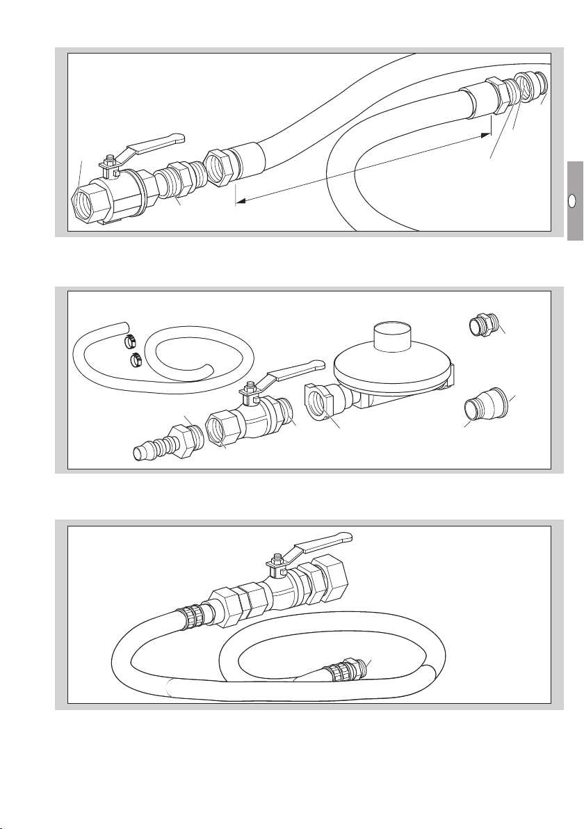
Connection kit for natural gas
Manual valve and gas hose to connect the gas combination control CG to the gas supply.
R 1"
Rp ¾"
Rp 1"
1,40 m
Rp 1"
R 1"
Connection kit: R 1" threaded connection, total length = 1.50m + reducing socket Rp1 – Rp¾",
Order No.: N52600071
Connection kit for propane
Rp ¾"
R ½"
R ½"
R ½"
ø 6 mm
R ½" Rp ½"
Rp ½" GP 70/GP 95/GP 120
GP 14/GP 40
Pressure reducer, manual valve, hose (length = 2m), 2 hose clamps, R½" double nipple for GP14/GP40,
R½ – Rp¾" reducing fitting for GP70– GP120, to connect the gas combination controlCG to the gas sup-
ply, OrderNo.: N52600025
R 3/8"
R ½"
ø 15 mm
Manual valve and hose (DVGW certified, length = 2m) to connect the gas combination controlCG to the gas
supply, OrderNo.: N52990209

GB-16
D
GB
F
NL
I
E
Spare parts
▷ When ordering spare parts, please quote the order number along with the designation and item no. of
the spare part as well as the heater serial number.
▷ When ordering spare parts which are not listed here below, please quote the edition of these operating
instructions and the heater serial number.
▷ Use original spare parts only to ensure the replacement complies with the requirements stipulated by the
manufacturer.
20
21 16
14, 15
13
19
5
22
4
22, 23
1
17
3
18
4
10
12 11 6
7, 8
9
5
Item
Order No. Designation
1N50400012 Multifan fan for GP 120, incl. impeller wheel, 4E-50-8PP
2N50400032 Safety grille for GP 120 fan, black
3N50260173 Pipe 178 mm, galvanized, R ¾"
4N50260144 Vane switch, complete, universal for all devices, incl. 2-core cable
5N52600008 Electrode holder for GP 95/GP 120
6N50260167 Burner baffle plate for GP 95/GP 120/RGA, Ø 48 mm
7N50400066 LPG nozzle for GP 120, 12 x Ø 1.8 mm
8N50400069 Natural gas nozzle for GP 120, 12 x Ø 3.3
9N50390005 Ignition electrode for GP 95/GP 120
10 N50260213 Ignition cable kit for GP 40 – GP 120, complete with plug and cap
11 N50390006 Ionization electrode for GP 95/GP 120
12 N50500080 Ionization cable kit for GP series, incl. plug and seal
13 N50260101 BCU 300 upper housing section, incl. electronics, Kromschröder THP-GW 84636001
14 N50260102 BCU 300 lower housing section, incl. ignition transformer
15 N50260109 Ignition transformer for gas, Eichhof E4718/55, 1-pin
16 N50260097 Temperature sensor for STM/STL, 6 x 45, L = 290 mm, TSK 1056 NTC (5 kΩ/25°C)
17 N50260171 90° male/female elbow, galvanized, R ¾"/Rp ¾"
18 N50400004 Pipe 300 mm, galvanized, R ¾"
19 N50280123
Gas combination control CG 220 for GP 70– GP 120, Kromschröder CG 220R01-DT2WF1Z
20 N50260119 Plug for pressure switch, grey
21 N50260118 Plug for valves, black
22 N50400200 Natural gas burner for GP 120, complete
23 N50400201 LPG burner for GP 120, complete
24 N50400102 Burner chamber for GP 120
25 N50260147 Protective cap for BCU, PVC, black, with viewing window
26 N50260148 Protective cap for gas combination control CG 220, PVC, black

GB-17
D
GB
F
NL
I
E
Technical data
Inlet pressure pu:
natural gas: 20 – 25 mbar,
propane: 35 – 50 mbar.
Setting of the gas pressure switch pW:
natural gas: 10 mbar,
propane: 30 mbar.
Gas connection: R ¾" external thread.
Material:
casing: stainless steel 430,
burner chamber: stainless steel 430,
BCU: PPE.
Ambient temperature:
-10 to +60°C. No condensation permitted.
Cycle lock: 15 s.
Capacity: 120kW.
Gas consumption:
natural gas L: ± 11.7 m3/h,
natural gas H: ± 9.9 m3/h,
propane: ± 8.6 kg/h.
Connection rating:
230VAC, -15/+10%, 50/60Hz, 735W.
Power consumption: IA/IN: ± 8 A/3.2 A.
Air circulation:
Controlled air flow: ± 6650 m3/h,
Heating: ± 8000 m3/h.
Jet length: 50 m.
Housing:
length: 1450 mm,
width (total): 650 m,
height/diameter: 532 mm,
weight: 45 kg.
Declaration of conformity
We, the manufacturer, hereby declare that the prod-
uctGP complies with the requirements of the listed
Directives and Standards.
Directives:
– 2009/142/EC
– 2004/108/EC
– 2006/42/EC
– 2006/95/EC
Standards:
– DIN 3362, EN 298
– EN 60730
– EN 1643, EN 525:2009
The relevant product corresponds to the type tested
by the notified body 0085.
The production is subject to the surveillance proce-
dure pursuant to Directive 2009/142/EC according
to annex II paragraph 3.
Elster-Instromet B.V.
Scan of the Declaration of conformity (D, GB) – see
www.docuthek.com

GB-18
D
GB
F
NL
I
E
Contact
If you have any technical questions, please
contact your local branch office/agent. The ad-
dresses are available on the Internet or from
Elster-Instromet B.V.
Munstermanstraat 6
7064 KA Silvolde
T +31 315 338-911
F +31 315 338-679
We reserve the right to make technical modifications
in the interests of progress.
orders.ermaf@elster.com,
www.ermaf.nl
Elster-Instromet B.V.
Sales Office
Postfach 2809, 49018 Osnabrück
Strohteweg 1, 49504 Lotte (Büren)
Germany
T +49 541 1214 702
F +49 541 1214 506
Goods return form
Name of the operator
P.O. Box/Street
Postcode and town/city
Tel.
E-mail
Returned by (Mr./Ms.)
Date
Number of returns
Heater serial number
Power supply [V/Hz]
Inlet pressure pu[bar]
Reasons for return
Description of fault
Desired action
Credit note Replacement Repair
Remarks
Date and signature
Please send returns back to your supplier.
Contact
This manual suits for next models
1
Table of contents
Other ermaf Heater manuals


