EROAD CoreHub Xtreme User manual

Parts and Equipment
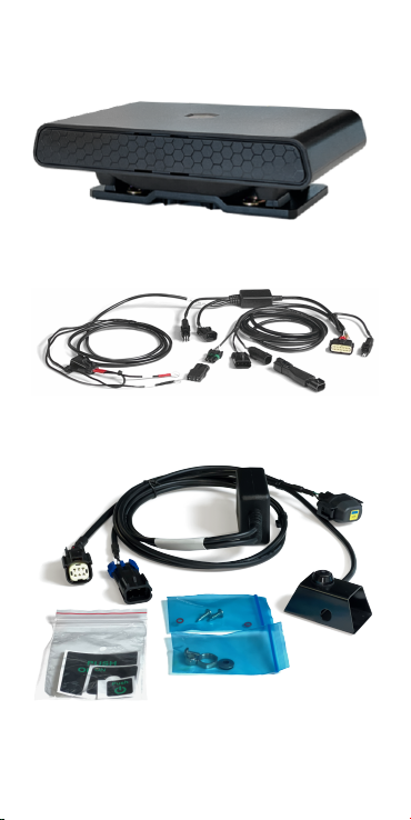
Included with the CoreHub Xtreme Install Kit:
CoreHub Xtreme (the “unit”)
Trailer and reefer Smart harness

•
•
•
•
•
•
Remote Start Stop (RSS) switch
harness (optional)
External antenna
Bracket
Zip ties, screws
Required tools
10, 12, 13, 14, and 17 mm deep well sockets
and wrenches
Diagonal flush cutters
Impact driver and 5/16ths bit for self-tapping
screws
18/20ga butt splice crimping tool
Propane torch
Platform to reach the top of the reefer safely

•
•
•
Pre-prep
Start the reefer to ensure it’s working with no
console alarms.
Ensure the reefer has its DataTrak/CarrierShot
firmware updated and operating.
Use the Safety Lockout Procedure; disconnect
any AC power source and battery NEGATIVE
terminal.
A ladder is fine for heights up to 2 m (7
ft) but should not be considered safe
for reaching the top of a reefer. Where
possible, use a scissor-lift, forklift
basket or similar stable, load-bearing
platform.
•
•
•
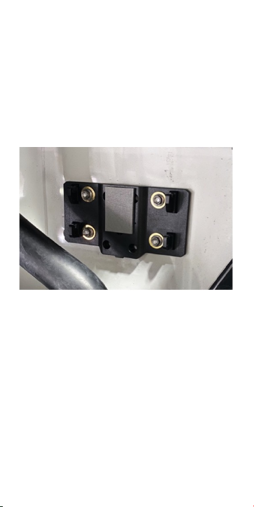
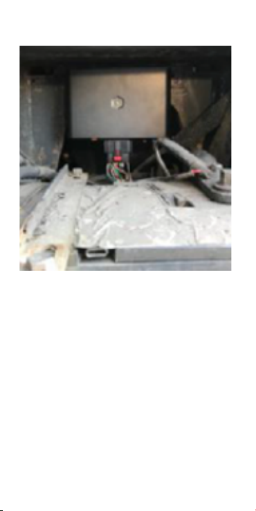
Mount the unit
Attach the unit to a flat surface half-way up the
inside of the reefer, such as above the APX
Control System display.
Use the holes in the mounting bracket to mark
the drilling points on the reefer, attach the
bracket accordingly, and mount the unit.
Keep the unit and the cables away from hot or
moving parts and high voltage lines (usually
colored orange).

Bracket
APX
Advance
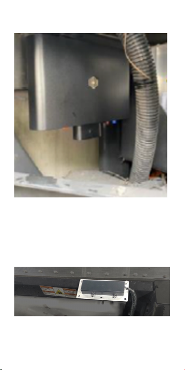
Vector 6500
Vector 8600
Mount the antenna
Attach the antenna to the top of the reefer or the
side front of the trailer. To function properly, it
must directly see the sky.
•
•
•
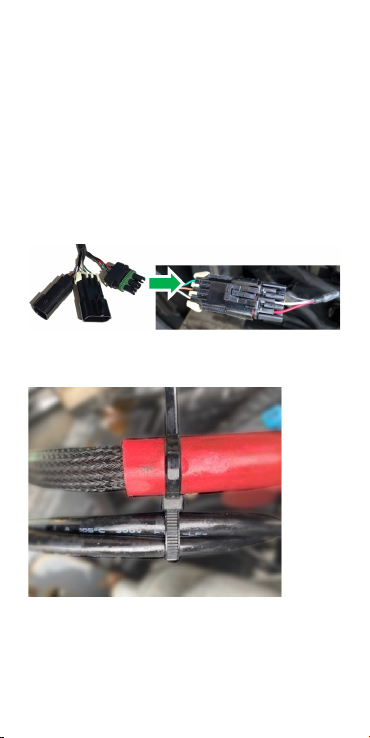
Plug the unit into the DataTrak
connector
Run the CoreHub Carrier harness cables to the
DataTrak connector by the APX display,
following the reefer frame or low-voltage lines
underneath. Do not zip-tie the harness to the
high-voltage (orange) power lines.
The main harness has connectors for reefer
data (Satcomm1), fuel sensor, and the J1
jumper and/or optional RSS switch.
Use the provided zip ties to space the cables.
Reefer data to CoreHub Xtreme
harness

•
•
Loop ties
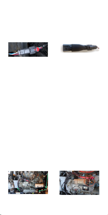
Attach the unit to J1 through
the adapter
Take the cap off the J1 and attach it to the
adapter.
Optional: Attach the unit to J1 with an
optional RSS switch
If you’re using the RSS switch for remote
controlling the unit, you do not need the adapter.
To install the switch, use the start/run toggle
switch nut and a self-drilling screw. If a few
switch threads are exposed, pull the switch to
start the nut.
Run the switch cable to the rear of the APX
display to avoid interference with doors and
compartment covers.
•
•
•
•
•
•
Tie the double-fuse holder near the APX display
for future use.
Plug the switch cable into the J1 and also into
the main harness.
Zip tie the old J1 jumper next to its connector
for possible future use (in case it’s needed for
emergency bypass).
Switch - Xtreme
harness
Adapter –
discard this if
using the RSS
switch
A thicker switch nut is included to replace the
existing one for easier tightening with a 14 mm
box wrench. Older models like the Advance have
the pushbutton mounted vertically with a machine
screw, sealing washer, and lock.
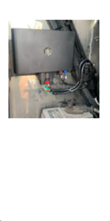
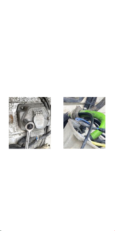
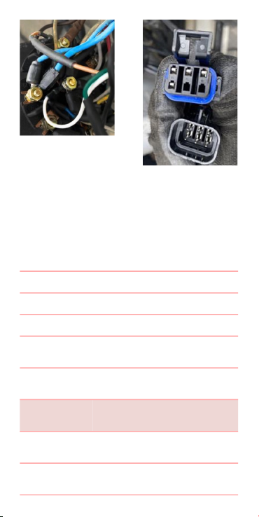
Connect reefer power
Connect reefer power and ground at the starter
solenoid ring studs.
The power cable is usually tied along a battery
feed to the solenoid using double-loop zip ties
or can follow the low-voltage cables under the
reefer.
The power fuse cover should be tied up with
wires coming out the bottom.
•
•
•
Optional: Connect to trailer ABS
module from the 7-way
connector
This step refers to using the optional trailer ABS
harness (part number HHXTR7) if each axel’s
odometer reading will be gathered for
maintenance purposes.
The unit receives data from the 7-way
connector.
Push the wires through the grommet. To help
this – especially if the rings are already
terminated – loosen the housing to
decompress the grommet, and then loop a wire
through the rings to pull them through.
Connect the blue, brown, and white wires on the
harness to the corresponding blue, brown, and
white power studs on the 7-way. Deep 3/8-inch
sockets can help tighten the nuts. Do not over-
tighten as the studs can break.
•
•
Reefer on; look for a solid red
light
Reconnect the battery.
Use the displayed table to troubleshoot the
unit’s status.
LED Color Flash Pattern Description
Light Pink Solid Bootup
Blue Solid Starting Services
Green Solid/ Ignition
On
Disconnected
from Cloud
Red Flashing/
Ignition Off
Connecting to
Cloud
Red Solid/ Ignition
Off
Connected to
Cloud
Orange Flashing/
Ignition On
Connecting to
Cloud
Orange Solid/ Ignition
On
Connected to
Cloud

•
•
•
•
•
•
Use the Installer app to activate
the unit and any wireless
sensors
Scan the QR code to download or search for
the Unit in Google Play or Apple’s App store.
You can also find the QR code in the box
the unit came in and on the back of the
unit itself. For convenience, place the QR
code on the inside of the APX display door.
Log in to the app using your 360 credentials.
Turn on the reefer and verify that the unit’s
status LED is solid red and that you are within
close Bluetooth range of the unit.
On the home screen, select Install.
Use the QR code to identify the unit to the app.
Enter the trailer and reefer information.

•
•
•
•
•
•
Add sensors one at a time by scanning their QR
codes. Each sensor has diagnostics.
Optionally, photo-document your work as
described below.
Photo verification
Installers are encouraged to photo-document their
work to assist in supporting work order
documents.Any digital camera may be used for 2
or 3 images per site, but images must:
Show the device clearly, mounted in place,
oriented appropriately.
Show connections and wiring secure and tidily
managed.
Indicate the environment in which the device is
installed (its position in the cab, or on the
asset).
You may also wish to note the vehicle make/
model for future reference.

1.
2.
3.
4.
a.
b.
5.
a.
Addendum: Migrating from a
TMU to CoreHub Xtreme
Unplug the TMU unit from all cabling.
Take photos of the installation beyond this
step. Any digital camera may be used.
Record/confirm the serial number of the TMU
before moving on.
Except for the fuel sensor and its cabling,
remove the antenna and any connected TMU-
related hardware (harnesses, door sensors,
etc.).
If installed, carefully remove the old TMU
switch attached to the Carrier controller unit.
This controller houses delicate components,
and some plastics become brittle with age.
Avoid forcing or prying the TMU switch from
the controller.
Once removed, fill holes with appropriate
grommets, and weatherproof with silicone.
Mount CoreHub Xtreme. Follow the steps
detailed in this guide, with the following call-
outs:
If using the same TMU locations for the
CoreHub Xtreme and its antenna: re-use the
Photos are evidence of a
compliant install. They protect
EROAD’s and the Installer’s
liability, should a future 3rd party
or incident affect compliance
integrity.

b.
c.
existing site as much as possible. Holes,
braces/supports, etc.
Be mindful of alterations to the reefer since
the TMU’s installation: additional
peripherals, special structures, etc., that
may affect CoreHub Xtreme’s installation,
its performance, or its structural integrity.
If using a door sensor, a new wireless door
sensor will need to be installed. (Wired door
sensors are no longer supported.)
Specifications
Cellular 4G LTE
WiFi 2.4 & 5 GHz 802.11 a/b/g/
n, 150 Mbps
Bluetooth Classic+BLE 4.2
GPS GPS, BEIDOU, GLONASS,
Galileo
Power 12 V, 0.5 A
24 V, 0.25 A
Int. Battery Lion rechargeable, or
Li-hybrid Supercap
(Optional)
Dimensions 160 x 90 x 25 mm (6.3 x
3.5 x 1 in)
250–400 g (0.5–0.8 lb)
Temperature -40 — +70°C
IP Rating IP66K

Pinout
PIN Function PIN Function
1 RX2 (normally
debug)
11 ADIO 5
2 TX2 (normally
debug)
12 ADIO 4
3 RX1 (shared J1708) 13 ADIO 3
4 TX1 (shared J1708) 14 ADIO 2
5 CAN LOW 15 ADIO 1
6 CAN HIGH 16 GND
7 1708-/ CAN1 LOW 17 1-Wire
8 1708+/ CAN1 HIGH 18 EXT 5/ 5V SW
9-VIN/ Solar Panel- 19 EX 12/ 12V SW
10 +VIN 20 Solar Panel+
Health and safety
There are no user-serviceable parts.

This device was designed to track land-based
Assets that may be subjected to rain, light
impacts and general mud and dust. Installation in
or on water-borne equipment is not
recommended and is not covered by EROAD's
warranty.
This device is factory-sealed; tampering will void
the warranty.
Before installing EROAD equipment in a vehicle
you must be, in Australia, an approved EROAD
installer and, in New Zealand, an accredited
EROAD installer. EROAD expects installers and
contractors to understand and follow all relevant
health and safety regulatory requirements.
The installer must wear appropriate Personal
Protective Equipment (PPE) for the install risk and
customer requirements. PPE may include safety
glasses, safety shoes, work gloves, hard hat, high
visibility vest, sun cream, sun hat and coveralls.
You must understand and comply with the safety
requirements of customers or third parties.
Avoid fitting EROAD equipment in locations that
could impede or cause injury to people. This
includes potential head strike zones on the
windshield or dashboard, airbag deployment
locations, seatbelts, and other safety-relevant
devices.
The vehicle must be parked and level, with the
parking brake engaged.
Before installation, check that other safety-
relevant equipment is working properly and report
any issues to the customer.
Before installers are permitted to work under or
around suspended equipment – held aloft with
slings, hoists, or jacks – ensure the equipment is
secured to prevent collapse or falls.
Other manuals for CoreHub Xtreme
1
Table of contents
Other EROAD Automobile Accessories manuals


Popular Automobile Accessories manuals by other brands


Southwing
Southwing SF-505 quick start guide

Cruz
Cruz Evo Rack Alu A30-140 Assembly instructions

TOP VEHICLE TECH
TOP VEHICLE TECH GRKVX04 installation manual

Fiamma
Fiamma LICENCE PLATE CARRIER Installation and usage instructions

DieselBoss
DieselBoss DB4 Quick tips and tricks

TAUBENREUTHER
TAUBENREUTHER 2086-03 manual


