Gewiss JOINON I-CON EVO Operating manual

JOINON I-CON
EVO RANGE
EN User and installation manual

2
I-CON EVOLUTION
CONTENT
Introductions�������������������������������������������������������������������������������������������������� 4
Features���������������������������������������������������������������������������������������������������������� 5
Applications ��������������������������������������������������������������������������������������������������� 5
1� I-CON User Interface����������������������������������������������������������������������������������� 6
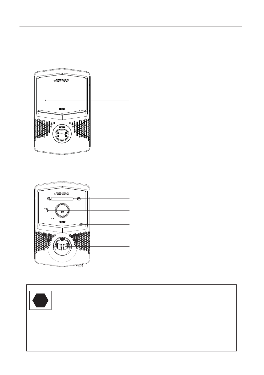
1�1 I-CON Basic����������������������������������������������������������������������������������������� 6
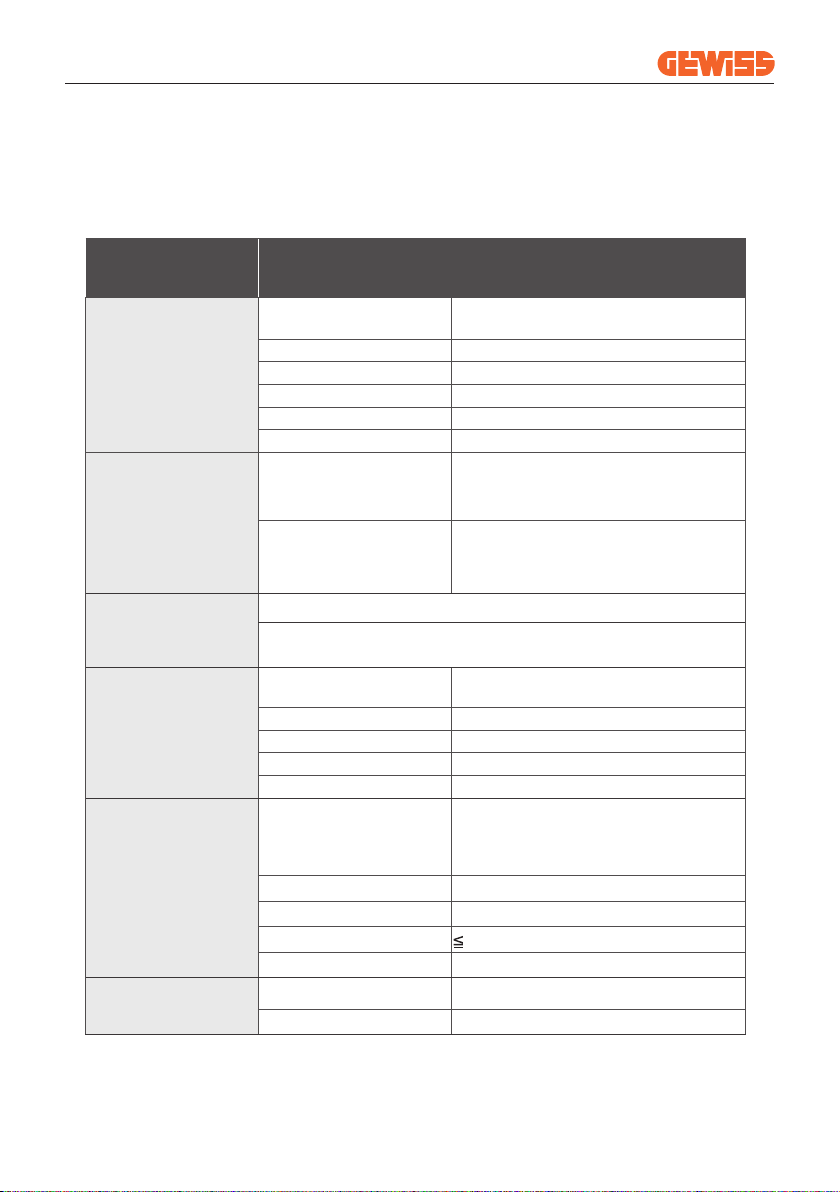
1�2 I-CON Premium ����������������������������������������������������������������������������������� 6
2� Specification ���������������������������������������������������������������������������������������������� 7
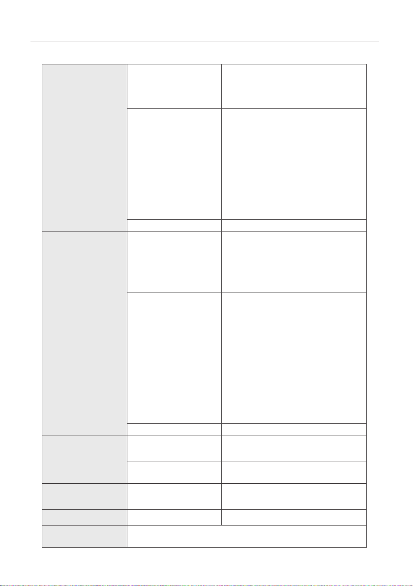
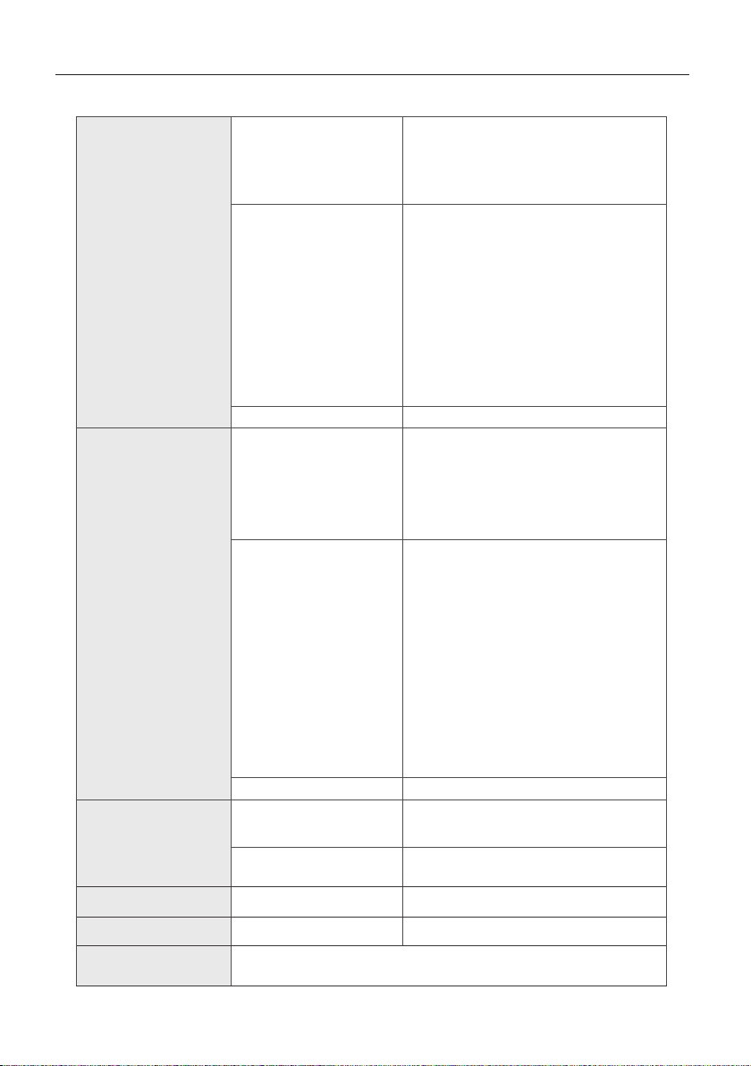
2�1 Product Specification ������������������������������������������������������������������������� 7
2�2 General and Specific countries requirements���������������������������������� 11
2�2�1 General requirements�������������������������������������������������������������������� 11
2�3 I-CON code description��������������������������������������������������������������������� 11
2�4 LED Indication and Operation Status ����������������������������������������������� 12
2�5 Dimensions��������������������������������������������������������������������������������������� 13
3� Device delivery and storage��������������������������������������������������������������������� 14
3�1 Delivery��������������������������������������������������������������������������������������������� 14
3�2 Device Identification������������������������������������������������������������������������� 14
3�3 Damage during transport ����������������������������������������������������������������� 14
3�4 Storage ��������������������������������������������������������������������������������������������� 14
4� Installation Instruction����������������������������������������������������������������������������� 15
4�1 Before Installation ���������������������������������������������������������������������������� 15
4�2 Installation area requirements��������������������������������������������������������� 16
4�3 Grounding and Safety Requirement ������������������������������������������������� 20
4�4 External protections to install���������������������������������������������������������� 20
4�4�1 RCD Protection������������������������������������������������������������������������������� 20
4�4�2 MCB Protection������������������������������������������������������������������������������ 20
4�5 External Current Transformer to install�������������������������������������������� 21
4�6 Installation Procedure ���������������������������������������������������������������������� 22
4�6�1 Opening the charging station�������������������������������������������������������� 22
4�6�2 Wall or pole installation����������������������������������������������������������������� 23
4�6�3 Roof protection������������������������������������������������������������������������������ 25
4�6�4 Wiring connection�������������������������������������������������������������������������� 25
4�7 Electrical check – Earth resistance ������������������������������������������������� 27
5� Functional Specification �������������������������������������������������������������������������� 27
5�1 Further special features ������������������������������������������������������������������� 28

3
5�1�1 Internal overheating ���������������������������������������������������������������������� 28
5�2 My JOINON App��������������������������������������������������������������������������������� 28
5�2�1 Sign up and Sign in ����������������������������������������������������������������������� 28
5�2�2 Digital commissioning - Create your home ���������������������������������� 29
5�2�3 Charging station pairing���������������������������������������������������������������� 29
5�2�4 Charging station setup ������������������������������������������������������������������ 30
5�2�5 Off-Peak Hours ������������������������������������������������������������������������������ 31
5�2�6 Random Delay�������������������������������������������������������������������������������� 32
5�3 Dynamic Load Management For The Charge Session���������������������� 33
6� How To Charge Your Electric Vehicle�������������������������������������������������������� 34
6�1 I-CON SingleCP ��������������������������������������������������������������������������������� 34
6�2 I-CON MultiCP without RFID reader�������������������������������������������������� 35
7� Dedicated requirements for UK Market ��������������������������������������������������� 35
7�1 Ozev Requirements��������������������������������������������������������������������������� 36
7�1�1 Smart functionalities �������������������������������������������������������������������� 36
7�1�2 Electricity supplier interoperability����������������������������������������������� 36
7�1�3� Loss of communications network access������������������������������������ 37
7�1�4 Safety��������������������������������������������������������������������������������������������� 37
7�1�5 Measuring system ������������������������������������������������������������������������� 37
7�1�6 Off-peak hours������������������������������������������������������������������������������� 38
7�1�7 Random delay�������������������������������������������������������������������������������� 38
7�1�8 Security������������������������������������������������������������������������������������������ 38
7�1�9 FW updates ������������������������������������������������������������������������������������ 39
7�2 Pen Fault������������������������������������������������������������������������������������������� 39
8� Network Setting���������������������������������������������������������������������������������������� 40
8�1Wi-Fi��������������������������������������������������������������������������������������������������� 40
8�1�1 Wi-Fi Hotspot ��������������������������������������������������������������������������������� 40
9� Error encoding and troubleshooting �������������������������������������������������������� 41
9�1 Error code list ����������������������������������������������������������������������������������� 41
9�2 Troubleshooting for the end user ����������������������������������������������������� 43
10� Product Disposal ������������������������������������������������������������������������������������ 46
11� Assistance ���������������������������������������������������������������������������������������������� 47

4
I-CON EVOLUTION
Introduction
To get access to the features oered by I-CON, it is important to download the My
JOINON app available in the Google and Apple stores. Search for the app in the
stores or scan the QRcode below.
JOINON I-CON Evolution is the best choice for powering battery electric vehicles
(BEVs) and plug-in electric vehicles (PHEVs).
It is designed for fast charging in public and private locations, such as retail and
commercial car parks, fleet charging stations, motorway service areas, workplaces
and homes.
JOINON I-CON Evolution has the advantage of being easy to install.
The wall-mounted design allows flexible and cost-eective installation for dierent
types of locations.
The AC charging solution also has network communication capability.
It can connect with remote network systems and provide electric car drivers with
real-time information, such as charging progress and billing information.
The AC charging solution has a simple user interface with security certifications
and an excellent waterproof and dustproof design, making it the best choice for
outdoor environments.
It is important to note that the information in this document is subject to
change without notice. Please download the latest version from
www.gewiss.com

5
Features
• The wall-mounted design makes installation easy and flexible.
• It oers customers the convenience of controlling the start and stop of charging
from an authorised RFID smart card or mobile APP (available on request).
• Built to the latest industry standards for AC charging.
• It has an outdoor rating to withstand solid and liquid intrusion in outdoor
environments, making the unit more stable and highly reliable.
• High-contrast screen interface with multifunctional buttons
Applications
• Single dwelling domestic properties
• Multi dwelling domestic properties
• Public and private parking areas
• Community parking areas
• Workplace parking areas
I-CON code I-CON BASIC DOMESTIC – SINGLE CP –
UP TO 22KW
GWJ3402CK I-CON Basic Single CP T2S 7.4KW UK
GWJ3404CK I-CON Basic Single CP T2S 22KW UK
GWJ3502GK I-CON Basic Multi CP (w/o auth) T2S 7.4KW UK
GWJ3504GK I-CON Basic Multi CP (w/o auth) T2S 22KW UK
The document is the user manual for the following charge points

6
I-CON EVOLUTION
1. I-CON User Interface
LED Indication
AC Connector
T2 Socket o Tethered cable
1.1 I-CON Basic
1.2 I-CON Premium
LED Indication
AC Connector
T2 Socket o Tethered cable
RFID reader (optional)
Matrix LED Display
Notice: According to EN-17186 requirement, this document lays
down harmonized identifiers for power supply for electric road
vehicles. The requirements in this standard are to complement the
informational needs of users regarding the compatibility between the
EV charging stations, the cable assemblies and the vehicles that are
placed on the market. The identifier is intended to be visualized at EV
charging stations, on vehicles, on cable assemblies, in EV dealerships
and in consumer manuals as described.
C

7
2. Specification
2.1 Product Specification
AC
INPUT
Voltage Rating 230 Vac (±15%)
400 Vac (±15%)
Max Input Current 32 A
Max. Input Power 22 kVA
Power Grid System TN / TT
Frequency 50/60 Hz
Electrical Distribution 1P+N+PE 3P+N+PE
Input Protection
Available inside the
charging station
•
PEN fault
•
OVP
•
OPP
External to the
charging station
•
MCB (2P or 4P up to 32A, Curve C
or D)
•
RCD (2P or 4P up to 40A, Type A,
30mA
Internal Protection
DC leakage (Trip for DC residual current at 6mA)
SPD protection (VM:115-750V - ITM: 6K-10K A
TA: -55°C - +85°C – Surge Current: 10kA)
Mechanical
Specifications
Weight • T2 socket model: 4,5 Kg
• T2 tethered cable: 5,5 Kg
Charging Cable Number 1
Charging Cable Length 6 m
Protection Degree IP 55
Mechanical resistance IK 10 (Excluding Display if present)
Environmental
Conditions
Operation Temperature
(external)
-25 °C; + 55°C * (Current derating
from 50°C)
* It must not be exposed to direct
sunlight
Storage Temperature -40°C; +70°C
Relative Humidity 5%~95% RH
Altitude 2000 m
Pollution degree 3
Communication External • Wi-Fi
Internal -
Model Name GWJ3402CK – GWJ3404CK →I-CON BASIC DOMESTIC
– SINGLE CP – UP TO 22KW

8
I-CON EVOLUTION
Regulation for EU
Directive
• 2014/53/EU
• 2011/65/EU + 2015/863
• Electromagnetic compatibility
EMC classification: B
Standard
• EN IEC 61851-1
• EN IEC 61851-21-2
• EN IEC 63000
• ETSI EN 301 489-3 V2.1.1
• ETSI EN 301 489-17 V3.2.4
• ETSI EN 301 489-52 V1.2.1
• ETSI EN 301 908-13 V13.2.1
• ETSI EN 300 328 V2.2.2
• ETSI EN 300 330 V2.1.1
• EN IEC 62311
Standard socket • EN 62196 Type 2 Mode 3
Regulation for the
UK
Regulation
• Radio Equipment Regulation 2017
(UK RED Regulations)
• The Restriction of the Use of
Certain Hazardous Substances
in Electrical and Electronic
Equipment Regulations 2012
Standard
• BS EN IEC 61851-1
• BS EN IEC 61851-21-2
• BS EN IEC 63000
• ETSI EN 301 489-3 V2.1.1
• ETSI EN 301 489-17 V3.2.4
• ETSI EN 301 489-52 V1.2.1
• ETSI EN 301 908-13 V13.2.1
• ETSI EN 300 328 V2.2.2
• ETSI EN 300 330 V2.1.1
• BS EN IEC 62311
• BS 8300-1
• paragraph 722.411.41(iv) of BS
7671:2018/A1:2020.
Standard socket • BS EN 62196 Type 2 Mode 3
User Interface
User Authorization • None
• Via app
Charge Status
Information • LED (always)
Charging Interface • T2 socket
Standby Power 30W
Other In UK the use of software controlled means cannot be used
to control isolating devices

9
AC
INPUT
Voltage Rating 230 Vac (±15%)
400 Vac (±15%)
Max Input Current 32 A
Max. Input Power 22 kVA
Power Grid System TN / TT
Frequency 50/60 Hz
Electrical Distribution 1P+N+PE 3P+N+PE
Input Protection
Available inside the
charging station
•
PEN fault
•
OVP
•
OPP
External to the
charging station
•
MCB (2P or 4P up to 32A, Curve C
or D)
•
RCD (2P or 4P up to 40A, Type A,
30mA
Internal Protection
DC leakage (Trip for DC residual current at 6mA)
SPD protection (VM:115-750V - ITM: 6K-10K A
TA: -55°C - +85°C – Surge Current: 10kA)
Mechanical
Specifications
Weight • T2 socket model: 4,5 Kg
• T2 tethered cable: 5,5 Kg
Charging Cable Number 1
Charging Cable Length 6 m
Protection Degree IP 55
Mechanical resistance IK 10 (Excluding Display if present)
Environmental
Conditions
Operation Temperature
(external)
-25 °C; + 55°C * (Current derating
from 50°C)
* It must not be exposed to direct
sunlight
Storage Temperature -40°C; +70°C
Relative Humidity 5%~95% RH
Altitude 2000 m
Pollution degree 3
Communication External • Wi-Fi
• Ethernet
Internal -
Model Name GWJ3502GK – GWJ3504GK →I-CON BASIC
DOMESTIC – MULTI CP – UP TO 22KW

10
I-CON EVOLUTION
Regulation for EU
Directive
• 2014/53/EU
•2011/65/EU + 2015/863
•Electromagnetic compatibility
EMC classification: B
Standard
• EN IEC 61851-1
• EN IEC 61851-21-2
• EN IEC 63000
• ETSI EN 301 489-3 V2.1.1
• ETSI EN 301 489-17 V3.2.4
• ETSI EN 301 489-52 V1.2.1
• ETSI EN 301 908-13 V13.2.1
• ETSI EN 300 328 V2.2.2
• ETSI EN 300 330 V2.1.1
• EN IEC 62311
Standard socket • EN 62196 Type 2 Mode 3
Regulation for the
UK
Regulation
• Radio Equipment Regulation 2017
(UK RED Regulations)
• The Restriction of the Use of
Certain Hazardous Substances
in Electrical and Electronic
Equipment Regulations 2012
Standard
•BS EN IEC 61851-1
•BS EN IEC 61851-21-2
•BS EN IEC 63000
•ETSI EN 301 489-3 V2.1.1
•ETSI EN 301 489-17 V3.2.4
•ETSI EN 301 489-52 V1.2.1
•ETSI EN 301 908-13 V13.2.1
•ETSI EN 300 328 V2.2.2
•ETSI EN 300 330 V2.1.1
•BS EN IEC 62311
•BS 8300-1
•paragraph 722.411.41(iv) of BS
7671:2018/A1:2020.
Standard socket • BS EN 62196 Type 2 Mode 3
User Interface
User Authorization • None
• Via app
Charge Status
Information • LED (always)
Charging Interface • T2 socket
Standby Power 30W
Other In UK the use of software controlled means cannot be used
to control isolating devices

11
2.2 General and Specific countries requirements
2�2�1 General requirements
In case of short-circuit, the value of l2t at the EV socket-outlet of
the Mode 3 charging station shall not exceed 75000 A2s
In case of short-circuit, the value of l2t at the vehicle connector
(case c) of the Mode 3 charging station shall not exceed 80000
A2s
2.3 I-CON code description
The I-CON is available in different versions depending on the connector type,
power of charge, display availability and other internal devices. The table below
describes the meaning of the number and letter.
GWJ3 x x x x
4
C
X
G
T
CK
GK
TK
CD
GD
CF
GF
TF
2
0
8
VERSION APPLICATION INTERNAL CONFIGURATION
+ MARKET
CONNECTOR TYPE CHARGE POWER
Domestic - SingleCP
Autostart + APP
KNX
RFID + APP
RS485 S + S/C + RFID + APP
Autostart + APP + OZEV
Autostart + APP + OZEV + S/C
RFID + APP + OZEV + S/C
Autostart + APP (DE)
Autostart + APP + S/C (DE)
Autostart + APP + TIC
Autostart + APP + S/C + TIC
RFID + APP + S/C + TIC
7,4kWType 2 socket
Semi-public - MultiCP - Premium
5 31
9
6 4
7
Domestic - MultiCP 11kW
Type 2 Tethered
Semi-public - MultiCP - Premium - MID
Semi-public - MultiCP - Basic 22kW
Semi-public - MultiCP - Basic - MID

12
I-CON EVOLUTION
2.4 LED Indication and Operation Status
Standby Fault Charging
Color Solid Flashing
No colour The charging station is OFF
The charging station is rebooting to apply the new FW
White
1) Connection between the APP and the charging
station is OK (via Wi-Fi). This overlaid the base
colour for 3 seconds.
2) The charging station is blocked in the booting
step. An unauthorised bootloader has been loaded
Hotspot Wi-Fi active
(overlaid on the base colour)
The charging station has a
SERVER role
The charging station has a
SERVER role
Green Charging station available
Waiting for the plug-in o
plug-out of the recharge
cable
Red
1) No internet connection for the charging station (via
Wi-Fi). This overlaid the base colour for 3 seconds.
2) The charging station recognized an internal error
3) The charging station recognizes an unauthorised
software
NA
Internal error NA
Blue Charge session ongoing – EV energized Charge session ongoing but
suspended
Orange NA
Downloading FW via OTA
applying new FW after
download
The charging station informs the customer of the status and which actions to
perform through the use of RGB LEDs.
Below the meaning of the various colours is explained. To get access to the
features offered by I-CON, it is important to download the My JOINON app
available in the Google and Apple stores.

13
283
137,5
51
435
375
2.5 Dimensions
Main Size of Charger:(Unit: mm)
ai168310447716_Dimensionale.pdf 1 03/05/23 11:01
106
240
Frontal and lateral view
Bottom view
37 3333 37
ai168310447716_Dimensionale.pdf 1 03/05/23 11:01

14
I-CON EVOLUTION
Keep the device packaged until the installation
3.2 Device Identification
The serial number of the device identifies it unequivocally.
In any communication with Gewiss, reference must be made to this number.
The device serial number is indicated on the technical data label (on the right side
of the front panel).
3.3 Damage during transport
If the device was damaged during transport:
1. Do not install it.
2. Notify the fact immediately (within 5 days of delivery).
If it is necessary to return the device to the manufacturer, the original packaging
must be used.
3.4 Storage
3. Device delivery and storage
3.1 Delivery
Failure to observe the instructions provided in this section could cause
damage to the device. The manufacturer declines all responsibility for
damage deriving from the failure to observe these instructions.
If the device is not installed immediately upon delivery, to avoid its deterioration,
proceed as indicated below:
•
To correctly conserve the charging station, do not remove the original packaging
until the moment it is installed.
•
Deterioration of the packaging (cuts, holes, etc.) prevents the correct conservation
of the charging station before installation. The manufacturer declines all
responsibility relative to the consequences caused by packaging deterioration.
•
Keep the device clean (remove dust, chips, grease, etc.) and avoid the presence
of rodents.
•
Protect it against water spray, welding sparks, etc.

15
•It is very important to Protecting the system against corrosive chemical products
and saline environments is very important.
Ambient storage conditions
Minimum temperature -40°C
Minimum temperature of the surrounding air -40°C
Maximum temperature of the surrounding air 70°C
Maximum relative humidity without condensation 95%
•
Cover the device with a protective breathable material to avoid condensation
caused by environmental humidity.
•
Charging stations kept in a warehouse must not be subjected to climatic
conditions other than those indicated below.
• Read all the instructions before using and installing this product.
• Do not use this product if the power cable or charging cable has any damage.
• Do not use this product if the enclosure or charging connector is broken or open
or if there is damage.
• Do not put any tool, material, finger or another body part into the charging or EV
connector.
• Do not twist, swing, bend, drop or crush the charging cable. Never drive over it
with a vehicle.
4. Installation Instruction
4.1 Before Installation
WARNING: The product should be installed only by a licensed contractor
and/or licensed technician by all building codes, electrical codes and
safety standards.
WARNING: A qualified installer should inspect the product before initial
use. Under no circumstances will compliance with the information in
this manual relieve user of his /her responsibilities to comply with all
applicable codes and safety standards.

16
I-CON EVOLUTION
• The wall on which the device is fastened must be solid. It must be possible to drill
the wall and insert wall plugs and anchor bolts that are suitable for supporting
the device’s weight.
• Power feed must be 1 or 3 Phase configuration with TN(-S)/TT grounding
systems.
• In installing the TN(-S) system, the neutral (N) and the PE of the power
distribution are directly connected to the earth. The PE of the charger equipment
is directly connected to the PE of power distribution and separate conductor for
PE and neutral (N).
• The product should be installed on a perfectly vertical wall.
CHARGING STATION CLASSIFICATION:
•Permanently connected
•Equipment for locations with no restricted access
•Class I equipment
4.2 Installation area requirements
I-CON will give the best of its functionalities if the installation area follows these rules.
WARNING: GEWISS is not responsible for wrong installations that could
cause damage to the product or EV connected to the charging station.

17
• Set up suitable fencing to isolate the construction
area from outside
• Close and secure all entrances when the site is
unattended
• Hang warning notices nearby which show the
following information: warning icon and phone
number of person in charge
• Install sufficient lighting fixtures
• Keep work areas (including access ways) free
from debris and obstructions
• Keep ground surfaces tidy and flat, to avoid
people tripping or being hurt by tools or other
objects
• Stack and store equipment and materials in a
tidy and stable manner
• Regularly clean up and dispose of waste
• Remove all surplus materials and equipment
after completion of work
• Beware of flammable materials and goods.
Keep them away from work areas.
1.Requirements for workplace conditions
2.Cleaning up
3.Fire hazards

18
I-CON EVOLUTION
• Erect a sunshade or shed to shelter workers from
the heat and sun
• Set up cooling equipment, such as exhaust fans
• Make water dispensers available
• Provide suitable protective clothing such as
a hat, sunglasses and long sleeves to protect
workers from heat stroke and UV rays
• Secure all scaffoldings, temporary structures,
equipment, and lose materials
• Check and implement SOP to ensure
disconnection of gas supplies, electrical circuits
and equipment
• Inspect worksites to ensure protection against
ingress of water or dust
• Inspect the drainage system for blockages and
remove them if found
• Stop all outdoor works except for emergency
works
4.Protection against high temperatures on the worksite
5.Inclement weather
• Have lifting gear and apparatus regularly inspected
and tested by qualified persons
• Isolate and cordon off lifting areas to keep out non-
construction personnel
• Ensure that lifting routes do not cross buildings or
people, and avoid collision with objects
• Do not exceed safe working load limits
6.Lifting operation

19
• Plan all work
• Turn off the power (work with live parts
de-energized whenever possible)
• LOTO (Lock Out, Tag Out)
• Live electrical work permit (input terminals with
HV after door open)
• Use personal protective equipment (PPE)
• Safe workplace conditions and space
• Adhere to other occupational health,
safety and security codes, such as those
published by OSHA
7.For on-site workers
Adhere to the following codes:
• NFPA-70E (Electrical Safety in the Workplace,
Shock Risk Assessment, Arc Flash Risk
Assessment)
8.Reference standards

20
I-CON EVOLUTION
• The product must be connected to a grounded, metal, permanent wiring system.
Connections shall comply with all applicable electrical codes. Recommend the
ground resistance be less than 10mΩ.
• Ensure no power is connected at all times when installing, servicing or
maintaining the charger.
• Use appropriate protection when connecting to the main power distribution
network.
• Use appropriate tools for each task
4�4�1 RCD Protection
The device is not included in the charging station or the packaging. The
protection must be installed above the charging station in the consumer unit.
Each charging station must be protected upstream by a residual current device
required by the low voltage electrical system standard. In particular, each station
must be protected upstream by a:
• Type A RCD (In compliance with one of the following Standards: IEC 61008-1,
IEC 61009-1, IEC 60947-2 and IEC 62423)
• 2Poles or 4Poles
• 40A Nominal Current
• 30 mA
4.3 Grounding and Safety Requirement
4.4 External protections to install
I-CON with a power of 7,4 kW requires 2 poles RCD
I-CON with a power of 11 and 22 kW requires 4 poles RCD
4�4�2 MCB Protection
Device not included in the charging station or the packaging. The protection
must be installed above the charging station in the consumer unit. Each charging
station must be protected upstream by a circuit breaker protection required by
the low voltage electrical system standard.
In particular, each station must be protected upstream by a:
• Curve C or D MCB
• 2Poles or 4Poles
• 32A Nominal Current
This manual suits for next models
4
Table of contents
Other Gewiss Automobile Accessories manuals
Popular Automobile Accessories manuals by other brands

dvblogic
dvblogic TF-MFD3 manual

Brodit
Brodit 810698 installation instructions

iKAMPER
iKAMPER WIND DEFLECTOR Assembly

Edscha Trailer Systems
Edscha Trailer Systems DrySystem quick guide

Metra Electronics
Metra Electronics 95-5817 installation instructions

Victory 4x4
Victory 4x4 ARMREST INTERIOR MOLLE PANEL Install instructions