Erskine Attachments Forestry Mulching Mower User manual

Forestry Mulching Mower
For
Skid Steer Loaders
Operator’s Manual
Maintenance
Parts Information
Read this Manual Before Use

2
TABLE OF CONTENTS
REFERENCE INFORMATION
Write the serial number for your attachment in the spaces below. Always refer to this serial
number when calling for service or parts.
Serial Number………….._____________
YOUR ATTACHMENTS DEALER
ADDRESS:
PHONE:
CONTACT:
SAFETY
3-4
SERIAL NUMBER/DECAL LOCATION
5-6
MOUNTING INSTRUCTIONS
7-8
OPERATING INSTRUCTIONS
9-11
ROUTINE MAINTENANCE
12-14
BOLT TORQUE INFORMATION
15
PARTS INFORMATION
16-20
GENERAL SPECIFICATIONS
21
TROUBLESHOOTING
22
WARRANTY
23
NOTE: Erskine Attachments LLC reserves the right to make
improvements in design or changes in specifications at any time without
notice and without incurring any obligations to install them on units
previously sold.

3
The signal words CAUTION, WARNING, or
DANGER are used to indicate hazards.
Indicates a potentially
hazardous situation which, if not avoided,
may result in minor or moderate injury.
Indicates a potentially
hazardous situation which, if not avoided,
could result in death or serious injury.
Indicates a potentially
hazardous situation which, if not avoided,
will result in death or serious injury.
The word IMPORTANT is used in the text when
immediate damage will occur due to improper
technique or operation.
The word NOTE is used to convey information that
is out of context with the manual text; special
information such as specifications, techniques,
reference information, and other information of a
supplementary nature.
The user is responsible for inspecting the machine
daily, and for having parts repaired or replaced when
continued use of the machine would cause damage,
excessive wear to other parts or make the machine
unsafe for continued operation.
If an operating procedure, tool device, maintenance
or work method not specifically recommended is
used, you must satisfy yourself that it is safe for you
and others. You must also ensure that the
attachment will not be damaged or made unsafe by
the procedures you choose.
Erskine Attachments LLC cannot anticipate every
possible circumstance that might involve potential
hazard. The safety messages found in this manual
and on the machine are therefore not all inclusive.
SAFETY
DO NOT perform maintenance on this machine until this manual has been read
and understood. In addition, read the Operation and Maintenance Manual(s)
pertaining to the attachment and the attachment carrier (“Loader”).

4
SAFETY
Improper operation can cause serious
injury or death.
Pre-operation
This attachment is designed to cut and mulch
brush and small trees. NEVER use this
machine for any other purpose.
To protect the operator, the loader must be fitted
with approved Forestry Door, Forestry Kit, and
Level II Falling Object Protective Structure
(FOPS) Kit.
Read the operator’s manual for the “Skid Steer
Loader.” NEVER allow untrained people to
operate.
Operating instructions must be given to everyone
before operating this attachment and at least once
a year thereafter in accordance with OSHA
regulations.
NEVER exceed the maximum recommended
input power or speed specifications for the
attachment. Over-powering or over-speeding the
attachment may cause personal injury and/or
machine damage.
Keep all shields, guards, and covers in place.
Do not modify equipment or add attachments that
are not approved by Erskine Attachments LLC.
Use adequate safety warning lights and devices
as required by local regulations. Obey all local
laws and regulations regarding machine operation
on public property.
Operation
Hydraulic connections may be hot after use. Use
gloves if connecting or disconnecting after use.
Check and be sure all operating controls are in
neutral before starting the engine.
Depending on how this attachment is used, dust
can be created. Prolonged exposure to dust can
cause chronic and acute health problems. A
NIOSH-approved respirator may be required.
Keep people away from loader, attachment and
discharge when in use. This attachment sends
objects flying and has rotating parts. NEVER
direct discharge toward people –rocks and debris
can be thrown hundreds of feet.
Operation (continued)
NEVER operate near embankments or terrain that
is so steep that rollover could occur.
Always stay in the operator position when using
the attachment.
Before leaving the operators position, disengage
hydraulic drive, lower the attachment to rest flat on
the ground, stop engine, set park brake, and wait
for all motion to stop. Even after disconnecting the
hydraulic drive, the disc will continue to spin for
several minutes. Do not leave the operator's
position until the disc is stopped. Do not allow
other people to approach the attachment while the
disc is spinning.
NEVER place hands in the discharge area or clear
debris while the engine is running.
Avoid High Pressure Fluids Hazard
Escaping fluid under pressure can
penetrate the skin causing serious
injury.
Avoid the hazard by relieving the
pressure before disconnecting
hydraulic lines.
Use a piece of paper or cardboard, NOT BODY
PARTS, to check for suspected leaks. Wear
protective gloves and safety glasses or goggles
when servicing or performing maintenance on
hydraulic systems.
If an accident occurs, see a doctor immediately.
Any fluid injected into the skin must be surgically
removed within a few hours or gangrene may
result.
Maintenance
NEVER
make adjustments, lubricate, clean, or
perform any service on the machine while it is in
operation.
Make sure the attachment is serviced on a daily
basis. Improper maintenance can cause serious
injury or death in addition to damage to the
attachment and/or your equipment.

5
SERIAL NUMBER AND SAFETY DECAL LOCATIONS
Serial Number Location:
It is important to refer to the serial number of the attachment when making repairs or ordering parts. Early or later
models (identification made by serial number) may use different parts, or it may be necessary to use different
procedures in doing a specific operation.

6
SERIAL NUMBER AND SAFETY DECAL LOCATIONS
Safety Decals Locations:
The locations of the safety decals are shown. If
these decals are missing, damaged, or painted over
they must be replaced. Call Erskine Attachments
LLC (218-435-4045) for replacement decals.
A
B
C
D
E
Part Number: 316078
Location: Each side of motor shield
Quantity: 2
Part Number: 314676
Location: On back of rear shield
Quantity: 1
Part Number: 200001
Location: Top of rear cover
Quantity: 1
Part Number: 400493
Location: One each rib
Quantity: 2
Large Brand Decal
Location: Each side of deck and top of
Location: motor shield
Quantity: 3
Part Number: 320359
Location: Top of motor shield
Quantity: 1

7
MOUNTING INSTRUCTIONS
After uncrating the attachment, use the following procedure to mount the attachment to the loader.
Coupler wedges or pins must extend through the holes in attachment. Levers must be
fully down and locked. Failure to secure wedges or pins can allow attachment to come off and cause
injury or death.
1. Use the step, safety treads, and grab handles to
get on and off the loader and attachment.
2. Sitting in the operator’s seat, lower seat bar and
fasten the seat belt.
3. Drive the loader to the rear of the attachment. Put
the loader quick attach coupler into the attachment
mounting bracket.
4. Tilt the loader coupler backward a small amount
until it is fully engaged in the brush mower
mounting bracket.
5. If you have manual levers, stop the engine and
engage the park brake. If not, proceed to step 6.
6. Secure the coupler locking mechanism that
attaches the attachment to the loader.
7. Connect the hydraulic quick couplers from the
attachment to the loader.
IMPORTANT: Wipe the ends of the hydraulic quick
couplers (both lead and loader) with a rag to remove
any possible contamination. Contamination can
cause hydraulic components to fail and is not
covered under warranty.
IMPORTANT: Make sure the quick couplers are
fully engaged. If the quick couplers do not fully
engage, check to see that the couplers are the same
size and brand. Do not force the quick couplers
together.
IMPORTANT: You must connect the small, third
hose which is the case drain hose, or you will
permanently damage the hydraulic motor.
NOTE: See the loader’s operator’s manual for further
instructions.
NOTE: Attachment is shipped with 16FJX (1-5/16”
Female JIC swivel) fittings on the ends of the lead
hoses and 8FJX (3/4” Female JIC swivel) on the case
drain hose.

8
MOUNTING INSTRUCTIONS
PRESSURE PORT
8. Make sure the hoses are properly routed to fit
your specific loader. If the hoses are not routed
correctly, hoses may get pinched or rub on tires
or tracks. Be sure to check the hose routing
through the full range of intended motion of the
attachment before operating it.
More than one routing may be acceptable
depending on the loader. Pick the routing that
best suits your loader.
IMPORTANT: Proper hose routing is the
responsibility of the owner and/or operator.
Pinched or stretched hoses are not covered
under warranty.
Mounting is now complete and you are ready to use
the attachment. Use reverse order of above
instructions to dismount the attachment from the
loader.
NOTE: Make sure the pressurized hose is routed to
the “MI” (MOTOR IN) port of the motor valve block.
If it isn’t, the attachment will not operate properly.
The proper hose to pressurize has PRESSURE
printed on the outer cover and/or a red cable tie on
the end.
If you are operating the loader controls correctly and
the mulcher still does not work, try switching the
hydraulic couplers around on the mulcher lead
hoses. This will effectively reverse the flow to the
motor.

9
OPERATING INSTRUCTIONS
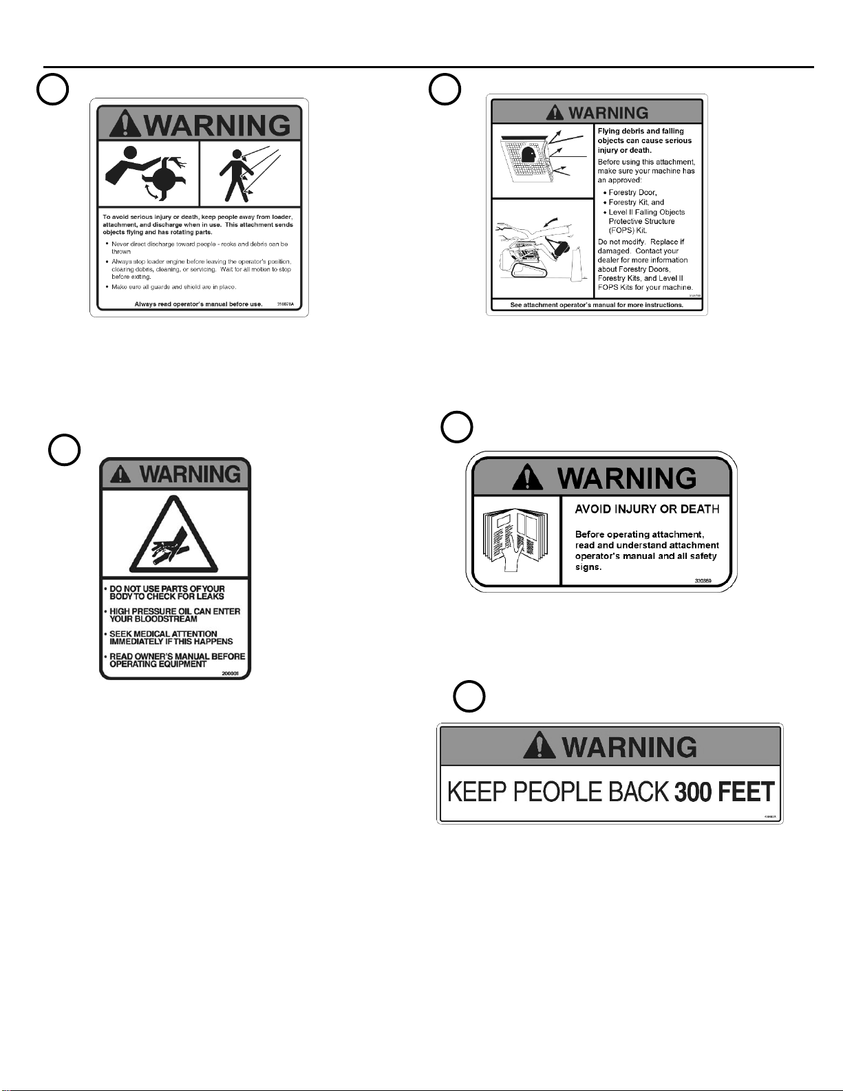
To avoid serious injury or death,
keep people away from the loader and attachment
when in use. The attachment can drop trees and
limbs in unpredictable directions. Make sure
there are no people, power lines, buildings, or
other objects that could be in the fell zone. Never
cut trees that could fall into these objects. Loader
must be equipped with approved Forestry Door,
Forestry Kit, and Level II Falling Object Protective
Structure (FOPS) Kit.
IMPORTANT: Before operating the attachment,
perform the service schedule for routine maintenance.
IMPORTANT: Certain materials can wrap around
parts of the attachment or cause other damage. Avoid
contacting materials like: metal wire, hoses, ropes,
tarps, mattresses, rugs, or plastics.
IMPORTANT: Certain land features can cause
damage. Inspect the cutting area and avoid
obstructions like drop offs, holes, rocks, debris, etc.
1. With the operator in the seat of the loader, the
seat belt fastened and the seat bar lowered (if
so equipped), start the engine.
2. With the loader boom lowered completely,
mulcher deck tipped back 0 to 10 degrees and
engine at low idle, activate the auxiliary
hydraulic system to start the disc rotation. Make
sure auxiliary hydraulic circuit is operating in the
High Flow mode. It can take up to 45 seconds
for the disc to spin up to full speed if starting
from a dead stop.
IMPORTANT: The attachment is designed to
operate from 33 to 45 gpm. Operating at higher flow
rates can cause serious damage to the mulching
head and will void the warranty.
IMPORTANT: Do not operate the attachment if
excessive vibration is present. Serious damage can
occur. Check to make sure that there is not debris
lodged between the teeth.
NOTE: Certain loaders may not operate in high flow
mode without a special wire harness. Others require
the control switches to be operated in a specific way.
It may also be necessary to switch the hose couplers
around to match your loader. (See loader’s
operator’s manual)
Mulching Trees Larger than 6”
1. First, you must decide if you can mulch the
standing tree as one piece, based on the trunk
diameter. If more than 6” diameter, use the
procedure below.
2. Cut the tree off between 0 and 3 feet above the
ground to minimize the chance of accidental
ingestion into the mulching chamber.
Always keep the attachment
low and slightly tilted back so that you are not
exposed to flying debris
3. Maintain pressure on the tree with the push bar
while you cut so the tree falls away from you.
4. Once on the tree has fallen, grind the remaining
standing portion using the teeth on the bottom of
the disc. Then proceed to mulch the limbs of the
tree either from the side or while straddling the
tree trunk.
5. For trees that are somewhat straight, you can cut
the top off and try to ingest that as one piece if it
is smaller than 6” diameter. To do this, straddle
the tree with the front of the deck angled down
slightly and drive forward while lowering the deck
onto the tree. Make sure you don’t try to ingest
such a large portion of the tree that it plugs the
mulcher. Keep the tree trunk between the 12
o’clock and 2 o’clock position on the disc for best
results.
6. For the trunk portion of the tree, use the teeth on
the bottom and edge of the disc to grind away
successive layers of material. You will need to
pause briefly after each cut to allow the disc to
speed up again. It usually works best to
approach the tree from the bottom end
NOTE: The type of wood being cut, available
horsepower and the ground conditions will determine
the best ground speed and cutting procedure.
IMPORTANT: While this attachment has been
designed to handle the extreme loads associated with
mulching whole trees, every machine has its limits.
Due to the large amount of spinning mass and high
speed of the disc, the operator must use care not to
ingest pieces of tree trunk larger than 10” diameter, as
this could overload the spindle. Any spindle damage
is considered to be the result of operator abuse, and
is not covered under warranty.

10
OPERATING INSTRUCTIONS
Mulching Trees Smaller than 6”
1. First, you must decide if you can mulch the
standing tree as one piece, based on the trunk
diameter. If the tree is a softwood of 6” diameter
or less (5” diameter or less for hardwood), use
the procedure below.
2. To properly mulch an entire tree, make sure the
disc is spinning at maximum RPM. This may take
up to 45 seconds if starting from a dead stop.
With the mulcher tipped back at a 20 to 45-
degree angle, raise the front of the mulcher about
3 feet to 6 feet off the ground. Position the
mulcher so the tree is in the disc ingestion zone
(between the 12 o’clock and 2 o’clock position)
Then slowly move into the tree and slowly raise
the loader arms to ingest the top portion.
Always keep the attachment
tilted back so that you are not exposed to
flying debris
3. Once the tree top is cut off and the disc speed
has recovered to full RPM, lower the attachment
slowly over the remaining tree trunk to mulch it.
If you lower the attachment too quickly you may
stall the disc. You may need to drive forward and
backward a small amount to ensure the teeth on
the bottom of the disc are engaging the tree trunk.
4. If the tree falls to the ground without being
ingested directly into the top of the disc, you can
still process the tree in one piece. To do this,
position yourself parallel to the tree trunk and
facing the bottom end. Lower the front of the
mulcher deck to the ground and feed the lower
end into the ingestion zone of the disc.
NOTE: When shutting down the attachment, the
inertia of the disc will cause it to continue spinning for
several minutes after the hydraulic drive is
disengaged. To stop the disc faster, grind a stump
with the hydraulic drive disengaged.
Before leaving the operators
position, disengage hydraulic drive, lower the
attachment to rest flat on the ground, stop engine,
set park brake, and wait for all motion to
stop. Even after disengaging the hydraulic drive,
the disc will continue to spin for several
minutes. Do not leave the operator's position or
allow other people to approach the attachment
until the disc has stopped.
INGESTION ZONE

11
OPERATING INSTRUCTIONS
“Down” Operating Position
“Up” Maintenance Position
Removing Material from a Clogged Disc
It is possible to plug the disc under certain
circumstances. These include ingesting too large of a
tree, ingesting a tree before the disc reaches
maximum RPM or ingesting more material than you
intended (i.e. two small trees at once).
If the disc becomes plugged, use the following steps
to clear the debris.
Option 1: Removal by hand
Teeth and debris can be sharp.
Wear gloves to protect your hands.
To avoid injury or death, never put
hands, feet, head, or objects in front of the
attachment when engine is running or when there
is an operator in the loader.
1. Lower the deck to the ground, stop the engine,
engage the park brake and exit the loader.
2. Manuallyremove built-up material from around the
disc. Pull in the direction that unwinds the debris
if possible.
Option 2: Rub against standing tree
1. Locate a stout standing tree.
NOTE: This will damage the tree bark, so only rub
on a tree that you do not want to keep.
2. With the auxiliary hydraulics turned off, tilt the
mulcher deck back to an angle between 0 and 30
degrees and press the front edge of the disc
against the tree trunk.
3. Keeping the disc in contact with the tree, turn to
the loader to the right (causing the disc to turn in
a counter-clockwise direction) to “unwind” the
plug. Repeat this step until the debris is loose
enough to remove by hand.
4. Lower the deck to the ground, stop the engine,
engage the park brake and exit the loader.
5. Manually clear the debris from the disc once
loosened.
Front Shield Position
To avoid injury or death, never put
hands, feet, head, or objects in front of the
attachment when engine is running or when there
is an operator in the loader.
The deck is equipped with a front deflector shield
which is intended to impede the flow of debris leaving
the disc and reduce the chances of debris flying long
distances. The shield should be left in the down
position during normal operation. However, it can be
lifted and pined in the up position to gain access to the
teeth for service or if needed to remove any debris
lodged in the disc.

12
___ _ROUTINE MAINTENANCE_________________
WARNING! Lower the attachment to rest on the skid shoes, shut down the engine, relieve
the hydraulic pressure to the attachment, wait for all motion to stop, and set park brake
before leaving the operator’s seat to perform service of any kind.
It is the operator’s responsibility to make daily inspections of the attachment and loader for damage, loose
bolts, fluid leaks, or anything else that could cause a potential service or safety problem. Preventive
maintenance is the easiest and least expensive type of maintenance.
IMPORTANT: Bolts and set screws can loosen after initial usage. After first hour of operation check all bolts
and set screws. This must also be done daily before operation. If nuts or bolts are missing or damaged,
replace immediately.
IMPORTANT: Fluids such as engine oil, gear lube, and hydraulic fluid must be disposed of in an
environmentally safe manner. Some regulations require that certain spills and leaks be cleaned in a specific
manner. Check local, state, and federal regulations for the correct disposal.
DAILY INSPECTION
Follow the mulching mower service schedule for routine maintenance.
Check the following items every 4 hours of operation:
1. Check teeth for cracks or excessive damage. Replace if necessary.
2. Check entire attachment for weld cracks or excessive damage. Replace if necessary.
3. Check teeth mounting hardware for proper torque of 350ft.-lbs. (475Nm).
4. Check all hardware. Retighten if necessary.
5. Check shields. Repair if damaged or replace if necessary.
6. Check for damaged or missing decals. Replace if damaged or missing.
7. Check for damaged or leaking hydraulic hoses or fittings. Replace or tighten.
8. Clean debris, leaves, grass, and flammable material from main frame area and under covers.
Check the oil level in the bearing carrier every 100 hours of operation. To check the oil, remove the motor
shield. Remove one of the large plugs on the top of the bearing housing cover. Use a long slender device,
like a screwdriver, to check that the oil is about ½” from the bottom of the plug hole. Reinstall the motor
cover when complete.
Change the oil after the first 100 hours of operation. Change the oil annually or every 1000 hours of
operation thereafter, whichever comes first. To change the oil, lift the rear cover and put a container under
the end of the oil drain hose. Tilt the front end of the mulcher up as far as possible to aid in the draining of
the oil.
To avoid injury or death, support the
front end of the mulcher with blocks or jack stands
after tilting it back.
Remove the plug in the end of the drain hose to start the
oil draining. A small percentage of the oil will remain in
the case when the flow stops. Replace the drain hose
plug. Lower the mulcher to a level orientation and refill
with new oil until the oil level is about ½” below the bottom
of the fill hole. The oil type is 80w-90 and the capacity is
about 110 oz. (3.4 qt.) if completely empty.
4

13
ROUTINE MAINTENANCE
Four-point tooth
Four-Point Tooth Removal
New and used teeth can be sharp.
Wear gloves to protect your hands.
1. Make sure lead hoses are disconnected from
loader before working on attachment. Connect
the attachment hydraulic couplers together if you
want to turn the disc by hand.
2. Remove the tooth locking bolt and tooth, and
set aside.
NOTE: Tooth may fall from the holder when
removing the tooth locking bolt. Always support
the tooth while removing the bolt.
3. Continue to do this in a directional manner until all
the teeth are removed from the disc.
4. Once all the teeth are removed from the disc,
inspect the disc and holders for excessive wear or
cracking.
NOTE: Check that the disc can turn freely. Also
check teeth, mounting hardware, and disc for
wear, cracking, or breakage, which can cause
excessive vibrations. Replace if damaged.
Four-Point Tooth Installation
1. If replacing teeth, always use a new bolt during
assembly.
2. Apply anti-seize compound to the bolt threads.
3. Insert tooth locking bolt through tooth holder, and
thread into tooth. Make sure to install the teeth on
the front side of the tooth holders to ensure proper
operation.
4. Tighten the bolt to 350 ft. lbs. (475 Nm) of torque.
5. Repeat procedure until all teeth have been
replaced.
NOTE: If a few of the teeth are damaged and a
small vibration occurs, it is sometimes possible to
rearrange the teeth to reduce the vibration. This
is done by putting equal amounts of broken teeth
on opposite sides of the disc. A small amount of
vibration is acceptable and normal. Always use
genuine Erskinereplacement teeth.

14
ROUTINE MAINTENANCE
Carbide tipped bullet tooth
Slot for inserting into tool
Installation of bullet tooth
Removal of bullet tooth
Rotating Four-Point Teeth
1. When the original side gets worn down or chipped,
the tooth can be turned either 90 or 180 degrees
to expose fresh cutting surfaces on the tooth.
Alternately, the four-point teeth can be lightly
sharpened using a flat disc grinder to bring an
edge back. Keep in mind that you are removing
the hard surface from the face of the tooth, so do
not grind too much.
IMPORTANT: Do not weld on the teeth. Modified
teeth may break during operation.
2. After rotating the tooth, re-torque the locking bolt
to 350 ft.-lbs. If bolts are damaged, replace them.
NOTE: If you reposition or replace worn teeth on
the disc, be sure to do the same to the tooth on
the opposite side of the disc to maintain disc
balance.
Bullet Teeth Replacement
The bullet teeth can be installed and removed by
using the supplied tool (located under the rear cover).
Slide the tool into the slot in the tooth as shown at
right, and hit the tool with a hammer to either install or
remove the tooth. Never hit the tooth directly with the
hammer –doing so will damage the tooth.
Cleaning the Attachment
1. Position the attachment flat on the ground.
To avoid injury or death, never
service the attachment in the raised position.
Always service with the attachment sitting flat
on the ground or supported by an approved
lifting device or blocks.
2. Remove the top shields to access the motor
cavities.
3. Use low pressure water or a small brush to
remove any unwanted dirt and debris.
Use care when removing any
debris wrapped around the teeth or disc. Disc
can rotate suddenly.
4. Reinstall shields when complete.

15
BOLT TORQUE INFORMATION ____________

16
PARTS INFORMATION___________________
ITEM
QTY
PART NO.
DESCRIPTION
STOCK NO.
1
1
340204
DECK MULCHING MOWER W/A
2
1
340203
DISC MULCHER W/A
(NO TEETH INCLUDED)

17
PARTS INFORMATION___________________
ITEM
QTY
PART NO.
DESCRIPTION
STOCK NO.
3
1
340304
COVER MOTOR W/A
4
1
340341
DEFLECTOR MULCHER W/A
9
2
340318
LATCH RUBBER 10.5 W/BRACKET
10
1
340339
PIN 1 X 20 W/H Z
11
1
65127
PIN COTTER 3/16 X 2
20
8
41125
RIVET 3/16 STEEL #64
22
4
13209
BOLT HEX
1/2 X 1-1/2 NC GR 5
23
4
33626
WASHER LOCK
1/2"
24
4
33010
WASHER FLAT
7/16"
25
4
15359
BOLT HEX
3/4 X 1-1/2 NC GR 8 YZ
43
20
15311
BOLT HEX
5/8 X 2 NC GR 8 YZ
SHOWN WITHOUT PUSH BAR
PARTS FOR CLARITY

18
PARTS INFORMATION___________________
ITEM
QTY
PART NO.
DESCRIPTION
STOCK NO.
5
1
340311
COVER DECK MM W/A
12
1
330864
HOLDER MANUAL CANISTER 12.5 X 2.25
13
1
201405
PIN HITCH 5/8 X 2-3/4
14
1
104410
PIN CLIP #9 5/32 X 3-1/16
15
2
340319
HINGE STRAP 4.25 WIDE 8 BOLT
16
2
340352
CLAMP RUBBER .625-1.375 (2 PACK)
17
18
37210
NUT REV LOCK
1/4 NC
18
2
21801
BOLT CARRIAGE
1/4 X 3/4 NC GR5
19
8
13003
BOLT HEX
1/4 X 3/4 NC GR 5
20
8
41125
RIVET 3/16 STEEL #64
21
8
32373
SCREW MACHINE
#10-32 THREAD CUTTING
22
1
320795
TOOL PICK REMOVAL ASPH/CONCRT
SHOWN WITHOUT PUSH BAR
PARTS FOR CLARITY

19
PARTS INFORMATION
ITEM
QTY
PART NO.
DESCRIPTION
STOCK NO.
2
1
340203
DISC MULCHER W/A
32
1
340218
PLATE BOLT MACHINED
33
12
340228
HOLDER TOOTH BOLT ON EDGE
34
22
340279
TOOTH FOUR POINT SHANKLESS
35
16
314830
TOOTH BULLET CP/RS CONCRETE
36
24
0161430
BOLT FLG 12PT 3/4-16 X 3
37
24
340343
PIN 1 X 1.5 HEX HEAD THREADED
38
24
33860
WASHER FLAT
7/16" HARDEND
39
24
18910
BOLT HEX
1/2 X 1 UNF GR 8 YZ
40
20
18958
BOLT HEX
5/8 X 1-1/2 NF GR 8 YZ
41
10
340229
HOLDER TOOTH BOLT ON TOP
42
10
340351
BOLT FLG
12PT 3/4-16 X 4
VIEWED FROM
BOTTOM/UNDERSIDE
VIEWED FROM TOP

20
ITEM
QTY
PART NO.
DESCRIPTION
STOCK NO.
6
1
340210
MOTOR HYD PISTON 125CC
7
1
340278
VALVE ASSM CHECK MM FIXED
8
1
340212
CARRIER BEARING MULCHER ASSM
110oz 80W/90
26
1
340266
O-RING 6" ID X 3/32 (2-163)
27
8
23416
BOLT SHCS 1/2 X 3-1/4 NC BO
COMES WITH VALVE BLOCK
28
1
201524
ADPT STR 12MB-8MJ
29
2
330800
ADPT ELB 16MB-16MJ-45
30
1
340356
HOSE 3/8 X 16 6FJX-6FJX
31
1
340208
HOSE 1/2 X 112 8FJX-8FJX
32
2
340206
HOSE 1 X 10⁶ 16FJX-16FJX
33
1
201515
ADPT STR 8MP-6MJ
34
1
320063
ADPT PLUG 6MJ
35
1
340334
STRAP ELASTIC 12"
36
1
340335
STRAP HANGING CINCH 3.8-5.1 OD
37
1
340353
WRAP HOSE PLASTIC 3.157 X 66 YEL
NOT SHOWN
PARTS INFORMATION___________________
Table of contents
Other Erskine Attachments Industrial Equipment manuals

Erskine Attachments
Erskine Attachments V-Plow User manual

Erskine Attachments
Erskine Attachments 200001 User manual

Erskine Attachments
Erskine Attachments VP48SM User manual

Erskine Attachments
Erskine Attachments 110X Maintenance and service guide

Erskine Attachments
Erskine Attachments Mini Pick-Up Broom User manual
Popular Industrial Equipment manuals by other brands

Siemens
Siemens SIMATIC NET RUGGEDCOM RX1511 installation manual

ABB
ABB HT583916 Operation manual

probst
probst FVZ-UNI operating instructions

technotrans
technotrans manroland beta.d 40 Original instruction manual

SCHUNK
SCHUNK ROTA-S plus 2.0 Assembly and operating manual

Pilz
Pilz PNOZ mc4p operating instructions