manuals.online logo
Brands
  1. Home
  2. •
  3. Brands
  4. •
  5. Erskine Attachments
  6. •
  7. Snow Blower
  8. •
  9. Erskine Attachments 2010X User manual

Erskine Attachments 2010X User manual

This manual suits for next models

2

Other Erskine Attachments Snow Blower manuals

Erskine Attachments 2020 Series User manual

Erskine Attachments

Erskine Attachments 2020 Series User manual

Erskine Attachments 54 User manual

Erskine Attachments

Erskine Attachments 54 User manual

Erskine Attachments 965RM User manual

Erskine Attachments

Erskine Attachments 965RM User manual

Erskine Attachments 620RP User manual

Erskine Attachments

Erskine Attachments 620RP User manual

Erskine Attachments Mini Snow Blade User manual

Erskine Attachments

Erskine Attachments Mini Snow Blade User manual

Erskine Attachments ES2000 User manual

Erskine Attachments

Erskine Attachments ES2000 User manual

Erskine Attachments 960R User manual

Erskine Attachments

Erskine Attachments 960R User manual

Erskine Attachments 725FM User manual

Erskine Attachments

Erskine Attachments 725FM User manual

Erskine Attachments 1080FM User manual

Erskine Attachments

Erskine Attachments 1080FM User manual

Popular Snow Blower manuals by other brands

Wen 20720BT instruction manual

Wen

Wen 20720BT instruction manual

Poulan Pro 420904 owner's manual

Poulan Pro

Poulan Pro 420904 owner's manual

Poulan Pro 421602 owner's manual

Poulan Pro

Poulan Pro 421602 owner's manual

Murray 624504X4A Instruction book

Murray

Murray 624504X4A Instruction book

Blizzard POWER PLOW 8100PP owner's manual

Blizzard

Blizzard POWER PLOW 8100PP owner's manual

Craftsman 486.24837 Operator's manual

Craftsman

Craftsman 486.24837 Operator's manual

Yard-Man E2B5 Operator's manual

Yard-Man

Yard-Man E2B5 Operator's manual

ST ST 526 A Operator's manual

ST

ST ST 526 A Operator's manual

MTD 3AA Operator's manual

MTD

MTD 3AA Operator's manual

Toro Power TRX 1428 OHXE Operator's manual

Toro

Toro Power TRX 1428 OHXE Operator's manual

Poulan Pro 416829 owner's manual

Poulan Pro

Poulan Pro 416829 owner's manual

MTD 319-180-00 owner's guide

MTD

MTD 319-180-00 owner's guide

Poulan Pro 437986 owner's manual

Poulan Pro

Poulan Pro 437986 owner's manual

Brute 1695565 Operator's manual

Brute

Brute 1695565 Operator's manual

Poulan Pro 420915 owner's manual

Poulan Pro

Poulan Pro 420915 owner's manual

GreenWorks SNF402 Operator's manual

GreenWorks

GreenWorks SNF402 Operator's manual

LOFTNESS 601D1 Operator's manual

LOFTNESS

LOFTNESS 601D1 Operator's manual

LOFTNESS 1082I Operator's manual

LOFTNESS

LOFTNESS 1082I Operator's manual

manuals.online logo
manuals.online logoBrands
  • About & Mission
  • Contact us
  • Privacy Policy
  • Terms and Conditions

Copyright 2025 Manuals.Online. All Rights Reserved.

Models 2010X/2410X/2410XL
Hydraulic Snowblowers
For
Skid Steer Loaders
Operator’s Manual
Maintenance and
Parts Information
D
Do
o
n
no
ot
t
u
us
se
e
o
or
r
o
op
pe
er
ra
at
te
e
t
th
hi
is
s
m
ma
ac
ch
hi
in
ne
e
u
un
nt
ti
il
l
t
th
hi
is
s
manual has been read and understood.
Read the Operation & Maintenance Manual entirely. When you see this
symbol, the subsequent instructions and warnings are serious – follow
without exception. Your life and the lives of others depend on it!
IMPORTANT
If this machine is used by an employee or is loaned or
rented to others, make certain that the operator(s) prior
to operating:
•Is instructed in safe and proper use.
•Reviews and understands the operation and
maintenance manual(s) pertaining to the machine.
Remember, the operator is responsible for the safe
operation and maintenance of the machine. Most
accidents can be prevented. Good safety practices not
only protect you, but also the people around you.
NOTE: Erskine Attachments LLC reserves the right to make
improvements in design or changes in specifications at any time
without notice and without incurring any obligations to install them on
units previously sold.
2
3
TABLEOFCONTENTS
REFERENCE INFORMATION
Write the serial number for your attachment in the spaces below. Always refer to this serial
number when calling for service or parts.
Serial Number………….._____________
YOUR ATTACHMENTS DEALER
ADDRESS:
PHONE:
CONTACT:
FOREWORD 4
SAFETY 5
SERIAL NUMBER/DECAL LOCATION 6-7
SET UP ASSEMBLY 8-12
MOUNTING INSTRUCTIONS 13-15
OPERATING INSTRUCTIONS 16-17
ROUTINE MAINTENANCE 18-22
TROUBLESHOOTING 23
PARTS INFORMATION 24-31
WIRE HARNESS INFORMATION 32
GENERAL SPECIFICATIONS 33-34
WARRANTY 35
FOREWORD
To The Owner/Operator:
DO NOT use or operate this machine until this manual has been read and
understood. If you require additional information, contact your Dealer or
Erskine Attachments LLC.
4
Operation and Maintenance Manuals are written to
give the owner/operator instructions on the safe
operation and maintenance of the product. For you
r
safety and the safety of other persons, you must
not operate, service, inspect or otherwise handle
this equipment before you have reviewed and
understood the Operation and Maintenance
Manual(s) pertaining to the attachment and the
attachment carrier, hereafter referred to as “loader”.
Throughout this manual reference may be made to
the left hand (LH) or right hand (RH) side. These
terms are used as viewed from the operator’s seat
facing forward.
In order to get the optimum performance and
efficiency that has been designed into this product,
read this manual thoroughly before setting-up,
operating, or performing maintenance procedures
on the machine.
It is the responsibility of the user to read the
operator’s manual and comply with the safety
instructions, operating instructions and
maintenance guidelines set forth in this manual.
CAUTION: Indicates a potentially
hazardous situation which, if not
avoided, may result in minor o
r
moderate injury.
The user is responsible for inspecting the machine
daily, and for having parts repaired or replaced
when continued use of the machine would cause
damage, excessive wear to other parts or make the
machine unsafe for continued operation.
The signal words CAUTION, WARNING, o
r
DANGER are used to indicate degree of hazards
and to warn against unsafe practices that may
cause personal injury and are used with
appropriate safety instructions. These signal words
are not to be ignored; your safety is involved.
WARNING: Indicates a potentially
hazardous situation which, if not
avoided, could result in death o
r
serious injury.
DANGER: Indicates a potentially
hazardous situation which, if not
avoided, will result in death o
r
serious injury.
The word NOTE is used to convey information that
is out of context with the manual text; special
information such as specifications, techniques,
reference information, and other information of a
supplementary nature.
The word IMPORTANT, is used in the text when
immediate damage will occur to the machine due to
improper technique or operation. IMPORTANT will
apply to the same information specified by NOTE,
only of an immediate and urgent nature.
Erskine Attachments LLC cannot anticipate every
possible circumstance that might involve potential
hazard. The safety messages found in this manual
and on the machine are therefore not all inclusive.
If an operating procedure, tool device, maintenance
or work method not specifically recommended is
used; you must satisfy yourself that it is safe for you
and others. You must also ensure that the machine
will not be damaged or made unsafe by the
procedures you choose.
SAFETY
Whenever you see this symbol, it means Attention!
Become Alert! Your Safety is involved.
Failure to obey warnings or instructions can cause
personal injury or death.
Operating instructions must be given to everyone before operating this machine and at least once a year
thereafter in accordance with OSHA regulations.
•
This attachment is designed for blowing snow
only. NEVER use this attachment for purposes
other than intended.
•NEVER modify equipment or add attachments
that are not approved by Erskine Attachments
LLC.
•Remember, YOU are responsible for the safe
operation and maintenance of the equipment.
Most accidents can be prevented. Good safety
practices not only protect you, but also the
people around you.
General Safety Instructions
•Read the operator’s manual for the “Skid Stee
r
Loader” to become totally familiar with the
controls and instruments. Know how to stop all
equipment operation in case of emergency.
•
A
void the possibility of personal injury and/o
r
machine damage. NEVER exceed the maximum
recommended input power or speed
specifications for the attachment.
•Check and be sure all operating controls are in
neutral before starting the engine.
5
•Disengage hydraulic drive, lower the attachment
to rest flat on the skid shoes, stop engine, set
park brake, and wait for all motion to stop before
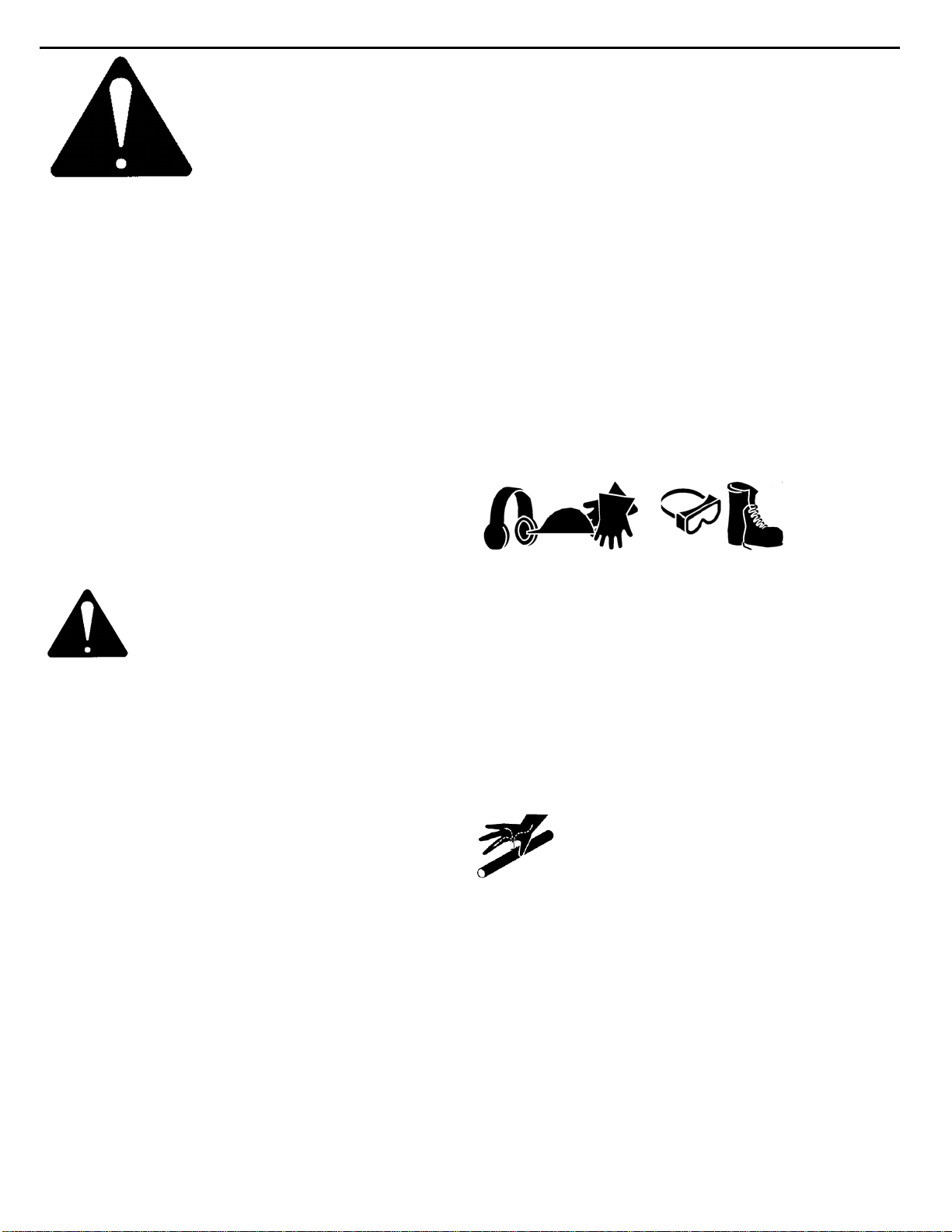
leaving the operator’s seat for any reason. Wear Protective Equipment
•Protective clothing and equipment should be
worn.
•Wear clothing and equipment appropriate for the
job. Avoid loose fitting clothing.
•Prolonged exposure to loud noise can cause
hearing impairment or hearing loss. Wear
suitable hearing protection such as earmuffs or
earplugs.
•Operating equipment safely requires the full
attention of the operator. Avoid wearing radio
headphones while operating equipment.
Avoid High Pressure Fluids Hazard
•Escaping fluid under pressure can penetrate the
skin causing serious injury.
•
A
void the hazard by relieving the pressure
before disconnecting hydraulic lines.
•Use a piece of paper or cardboard, NOT BODY
PARTS, to check for suspected leaks. Wear
protective gloves and safety glasses or goggles
when working with hydraulic systems.
•If an accident occurs, see a doctor immediately.
A
ny fluid injected into the skin must be
surgically removed within a few hours or
gangrene may result.
WARNING: Before adjusting, o
r
servicing the unit, stop the engine
and relieve all hydraulic pressure b
y
opening the control valve.
•Keep all shields, guards, and covers in place.
•Stay clear of the attachment when machine is
running.
•NEVER make adjustments, lubricate, or perform
any service on the machine while it is in
operation.
•NEVER operate this attachment within 100 feet
(30m) of people, or pets.
•NEVER operate near embankments or terrain
that is so steep that rollover could occur.
•NEVER allow children or untrained persons to
operate.
•DO NOT permit riders on equipment.
•Use adequate safety warning lights and devices
as required by local regulations.
•Obey all local laws and regulations regarding
machine operation on public property.
SERIAL NUMBER AND SAFETY DECAL LOCATIONS
Serial Number Location:
It is important to refer to the serial number of your attachment when making repairs or ordering parts. Early or
later models (identification made by serial number) may use different parts, or it may be necessary to use
different procedures in doing a specific operation. Serial number plate is located on the right rear side of
body.
6
B
G
D
C
F
A
ESerial Plate
SERIAL NUMBER AND SAFETY DECAL LOCATIONS
A
Part number: 102935
Location: On each side of blower assembly
Quantity: 2
7
C
B
Part number: 200001
Location: Back right side of blower
assembly
Quantity: 1
D
E
Part number: 102946
Location: Front of chute assembly, adjacent
to chute opening
Quantity: 1 Part number: 102957
Location: Sides of chute assembly
Quantity: 2
Part number: 300445 (Motor Package)
Location: back of blower under serial plate
Quantity: 1
F
Part number: 103206
Location: Chute rotation chain cover.
Quantity: 1
G
Safety Decals Locations:
The locations of the safety decals are shown. I
f
these decals are missing, damaged, or painted
over they must be replaced. Call Erskine
Attachments LLC (218-687-4045) for replacement
decals.
Part number: 320751 (2010) OR 320752 (2410)
Model Decal
Location: back left side of blower
Quantit
y
: 1
____________________SET UP ASSEMBLY ___________________
Remove screws to disassemble crate.
Remove chute from plastic bags.
8
The mounting plate can be installed in the “lower”
position for most skid steers with standard sized
tires, or in the “middle” or “upper” position for skid
steers with taller or oversized tires. The
mounting plate position can also be adjusted to
change the pitch of the blower in the working
position.
CAUTION: Make sure the bolts on
the mounting plate are tight. If you
remove the mounting plate,
retighten the bolts to 130 ft-lbs.
CRATE REMOVAL AND ASSEMBLY
____________________SET UP ASSEMBLY ___________________
Remove one of the roller guides from the
blower housing by removing the bolt securing
the roller guide.
9
A
fter unpacking the chute, slip the chute into
the grooves on the two remaining roller guides.
Reinstall the roller guide and bushing with bol
t
and lock nut.
IMPORTANT: Tighten lock nut to 75 ft-lbs
Rotate the chute to the straight forward
position.
Remove the chain shield.
Loosen the chute rotation motor bolts. Push
the motor all the way towards the chute.
Install the No. 40 roller chain around the
sprocket.
Tighten the chute chain by pulling the motor
outward to remove all slack. Tighten the
motor bolts and install the chain shield.
CAUTION: Do not operate the
snowblower without the chain
shield in place.
DISCHARGE CHUTE INSTALLATION
DISCHARGE CHUTE INSTALLATION (continued)
____________________SET UP ASSEMBLY ___________________
Install the cylinder with the rod end to the
deflector ears. Fasten with two 1/2” bolts.
NOTE: Usually the hoses will remain
connected to the cylinder when the chute is
removed.
IMPORTANT: Be sure the hoses are
routed properly through the hose “hook”
to allow the chute to rotate freely in both
directions without the hoses getting
caught.
PROPER HOSE ROUTING IS THE
RESPONSIBILITY OF THE OWNER AND/OR
OPERATOR. PINCHED OR STRETCHED
HOSES ARE NOT COVERED UNDER
WARRANTY.
Adjusting the Skid Shoe Height
NOTE: Skid shoes on the 2010, 2410 and
2410XL snowblowers are optional
equipment.
Raise the loader arms and tilt the
snowblower back just enough to remove the
skid shoe (about 12 inches off the ground).
Stop the engine and exit the loader.
Remove the lynch pin on the skid shoes. Install
washers on the bottom for the desired skid
shoe height. Reinstall the lynch pin.
10