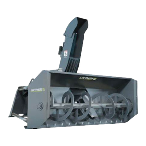
Erskine Attachments 54 User manual

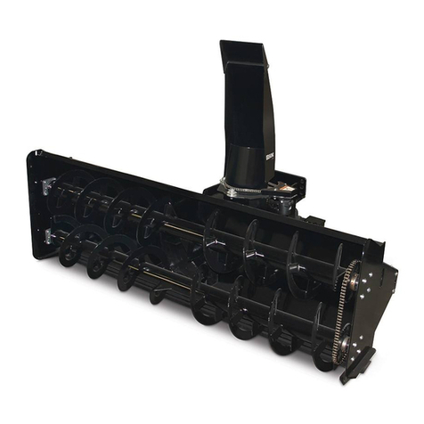
Utility Snowblower
54” –60” – 72” –84” Models
Rear Mounted –CAT. I
3-Point Snowblower
For
Compact Tractors
Operator’s Manual
Set-Up Assembly
Maintenance
Parts Information
Read this Manual Before Use

2
NOTE: Erskine Attachments LLC reserves the right to make
improvements in design or changes in specifications at any time without
notice and without incurring any obligations to install them on units
previously sold.
TABLE OF CONTENTS I
SAFETY
3-4
SERIAL NUMBER/DECAL LOCATION
5-6
SET-UP ASSEMBLY
7-12
MOUNTING INSTRUCTIONS
13-14
OPERATING INSTRUCTIONS
15-16
ROUTINE MAINTENANCE
17-20
BOLT TORQUE INFORMATION
21
PARTS INFORMATION
22-29
GENERAL SPECIFICATIONS
30
WARRANTY
31
REFERENCE INFORMATION
Write the serial number for your attachment in the spaces below. Always refer to this serial
number when calling for service or parts.
Serial Number………….._____________
YOUR ATTACHMENTS DEALER
ADDRESS:
PHONE:
CONTACT:

3
The signal words CAUTION, WARNING, or
DANGER are used to indicate hazards.
Indicates a potentially
hazardous situation which, if not avoided,
may result in minor or moderate injury.
Indicates a potentially
hazardous situation which, if not avoided,
could result in death or serious injury.
Indicates a potentially
hazardous situation which, if not avoided,
will result in death or serious injury.
The word IMPORTANT is used in the text when
immediate damage will occur due to improper
technique or operation.
The word NOTE is used to convey information that
is out of context with the manual text; special
information such as specifications, techniques,
reference information, and other information of a
supplementary nature.
The user is responsible for inspecting the machine
daily, and for having parts repaired or replaced when
continued use of the machine would cause damage,
excessive wear to other parts or make the machine
unsafe for continued operation.
If an operating procedure, tool device, maintenance
or work method not specifically recommended is
used, you must satisfy yourself that it is safe for you
and others. You must also ensure that the
attachment will not be damaged or made unsafe by
the procedures you choose.
Erskine Attachments LLC cannot anticipate every
possible circumstance that might involve potential
hazard. The safety messages found in this manual
and on the machine are therefore not all inclusive.
Throughout this manual, reference may be made to
the left hand (LH) or right hand (RH) side. These
terms are used as viewed from the operator’s seat
facing front.
SAFETY
DO NOT use or perform maintenance on this machine until this manual has been
read and understood. In addition, read the Operation and Maintenance
Manual(s) pertaining to the attachment and the attachment carrier (“Tractor”).

4
SAFETY I
Improper operation can cause serious
injury or death.
Pre-operation
This attachment is designed for blowing snowonly.
NEVER use this attachment for any other purpose.
Read the operator’s manual for the “Compact
Tractor”. NEVER allow untrained people to
operate.
Operating instructions must be given to everyone
before operating this attachment and at least once
a year thereafter in accordance with OSHA
regulations.
NEVER exceed the maximum recommended input
power or speed specifications for the attachment.
Over-powering or over-speeding the attachment
may cause personal injury and/or machine
damage.
Keep all shields, guards, and covers in place.
Do not modify equipment or add attachments that
are not approved by Erskine Attachments LLC.
Use adequate safety warning lights and devices as
required by local regulations. Obey all local laws
and regulations regarding machine operation on
public property.
Operation
Avoid loose fitting clothing. Clothing or hair caught
in moving parts maylead to serious injury ordeath.
Hydraulic connections may be hot after use. Use
gloves if connecting or disconnecting after use.
To protect the operator from hearing loss, ear
protection is required unless the tractor is
equipped with a noise reduction cab that meets
OSHA 1910.95 standard.
Always wear eye protection that meets z87.1 or
use with an enclosure that provides similar
protection.
Check and be sure all operating controls are in
neutral before starting the engine.
Operation (continued)
Keep people at least 100 feet away from the
tractor, attachment, and discharge when in use.
This attachment sends objects flying and has
rotating parts. NEVER direct discharge toward
people –rocks and debris can be thrown.
NEVER operate near embankments or terrain that
is so steep that rollover could occur.
Always stay in the operator position when using
the attachment.
Before leaving the operator’s position, disengage
PTO drive, lower the snowblower to rest flat onthe
ground, stop engine, set park brake, and wait for
all motion to stop.
NEVER place hands in the discharge chute or
clear debris while the engine is running.
Avoid High Pressure Fluids Hazard
Escaping fluid under pressure can
penetrate the skin causing serious
injury.
Avoid the hazard by relieving the
pressure before disconnecting
hydraulic lines.
Use a piece of paper or cardboard, NOT BODY
PARTS, to check for suspected leaks. Wear
protective gloves and safety glasses or goggles
when servicing or performing maintenance on
hydraulic systems.
If an accident occurs, see a doctor immediately.
Any fluid injected into the skin must be surgically
removed within a few hours or gangrene may
result.
Maintenance
NEVER make adjustments, lubricate, clean, or
perform any service on the machine while it is in
operation.
Make sure the attachment is serviced on a daily
basis. Improper maintenance can cause serious
injury or death in addition to damage to the
attachment and/or your equipment.
5
SERIAL NUMBER AND SAFETY DECAL LOCATIONS
Serial Number Location:
It is important to refer to the serial number of the attachment when making repairs or ordering parts. Early or later
models (identification made by serial number) may use different parts, or it may be necessary to use different
procedures in doing a specific operation.

6
Safety Decals Locations:
The locations of the safety decals are shown. If these decals are missing, damaged, or painted over they must
be replaced. Call Erskine Attachments LLC (218-435-4045) for replacement decals.
SERIAL NUMBER AND SAFETY DECAL LOCATIONS________
Small Brand Decal
Location: On each side of snowblower body
Quantity: 2
C
Part number: 200001
Location: Back right side of snowblower body
Quantity: 1 w/ opt hyd chute rotate
B
Part number: 103206
Location: On auger drive chain cover &
Location: optional chute rotation chain cover
Quantity: 1 standard, or 2 w/ opt hyd chute rotate
D
Part number: 102946
Location: On front of chute
Quantity: 1
A
Part number: 102935
Location: On each side of snowblower body
Quantity: 2
E
Part number: 102957
Location: On each side of chute
Quantity: 2
F
Part number: 201415
Location: On top of gearbox cover
Quantity: 1

7
SET-UP ASSEMBLY
Manual Rotation Discharge Chute Installation
1. Bolt the hand crank support bracket to the upper
arm, and insert the crank tube. Bolt the lower end
of the crank tube to the spool. The crank handle
length is adjustable. Start with the crank in the
shortest position until the snowblower is mounted
to the tractor for the first time.
IMPORTANT: Make sure the crank handle will
not contact the operator or any part of the tractor
through the entire range of motion.
2. Remove one of the roller guides from the
snowblower housing by removing the bolt
securing the roller guide.
3. After unpacking the chute, slip the chute into the
grooves on the two remaining roller guides.
4. Reinstall the roller guide and bushing with bolt and
lock nut.
IMPORTANT: Tighten each roller guide lock nut
to 75 ft.-lbs.
5. Rotate the chute so it is facing the front right
corner of the snowblower body (as viewed seated
in the tractor, facing forward).
6. Feed one end of the cable through the rear hole
of the spool, through the cable guide link, and
around the back of the chute as shown. Tighten
the set screw to lock the cable in place, leaving a
short tail sticking out.
7. Run the cable backwards through the chain links
in such a way that the cable will bind when
tightened. Method can vary, as long as the cable
binds tightly to the chute when tightened.
8. Thread the cable back through the cable guide.

8
SET-UP ASSEMBLY
9. Turn the crank handle clockwise to wind up the
cable on the lower part of the spool. Keep tension
on the loose end of the cable while cranking so
that the cable on the spool doesn’t unwind. Stop
cranking when the chute faces the front left corner
of the snowblower body. The chute should rotate
clockwise, as viewed from above, to reach this
position. The position of the chute does not need
to be exact, andcan be varied to help with the next
step.
10. Thread the remaining end of the cable through the
spool. The ends of the cable should be facing in
opposite directions. The crank position can be
changed slightly to aid in threading the cable and
tightening the set screw. Make sure the cable on
the spool remains tight. Pull all the slack out of
the cable before tightening the set screw.
11. Trim the cable ends as required.

9
SET-UP ASSEMBLY
Hydraulic Rotation Discharge Chute Installation
1. Remove one of the roller guides from the
snowblower housing by removing the bolt
securing the roller guide.
2. Remove the chain cover from the snowblower
housing by removing the two bolts securing the
cover.
3. After unpacking the chute, slip the chute into the
grooves on the two remaining chute guides.
4. Reinstall the roller guide and bushing with bolt and
lock nut.
IMPORTANT: Tighten each roller guide lock nut
to 75 ft.-lbs.
5. Rotate the chute to the straightforward position.
6. Loosen themotor mount bolts, and push the motor
all the way toward the chute.
7. Install the No. 40 roller chain around the motor
sprocket.
8. Pull the motor away from the chute until all slack
is removed from the roller chain, and tighten the
motor mount bolts to secure the motor in place.
IMPORTANT: Do not overtighten roller chains.
Tighten only enough to remove slack.
9. Reinstall the chain cover and two bolts.
Do not operate the
snowblower without the chain shield in
place. Moving parts may cause injury or
death. Always replace guard after servicing.

10
SET-UP ASSEMBLY
Mounting and Adjusting the Snowblower
1. Install the splined yoke of the driveline on the
snowblower gearbox shaft. This end of the
driveline is secured with a sliding lock collar like
the tractor end. Pull back on the collar and push
the yoke onto the gearbox shaft. Release the
collar and make sure it is securely locked in place
on the shaft.
Make sure the PTO master
shield is secured in its operating position.
Never operate the snowblower with missing
PTO shield.
2. The mounting arms are designed to be used on
the standard Category I 3-point hitch. They are
also quick hitch compatible. Be sure to pay extra
attention to the driveline length when using the
snowblower with a quick hitch. Make sure there
is proper engagement throughout the entire range
of motion.
3. Mount the snowblower to the tractor (see
“Mounting Instructions” on pages 13-14).
4. The snowblower may need to be tilted rearward
somewhat in order to create a straighter driveline
angle from the tractor PTO shaft to the
snowblower gearbox. This can be accomplished
by lengthening the tractor’s 3-point top link (refer
to the tractor’s operator’s manual for top link
adjustment instructions). The degree of backward
tilt depends on the tractor size and PTO location.
Example: The higher the tractor PTO shaft is
above the ground, the more snowblower
backward tilt is required.
IMPORTANT: It is extremely important to keep
the driveline angle as straight as possible while
the snowblower is under load, as this reduces
heat buildup and the chance of bearing failure in
the driveline U-joints.

11
SET-UP ASSEMBLY
5. After the snowblower backward tilt is determined
and set, the driveline telescoping length must be
checked.
6. With the snowblower resting on the ground,
connect the driveline to the tractor PTO shaft and
mark the location of overlap on the driveline.
Check to make sure that there is sufficient
clearance between the driveline and the tractor
drawbar. If there is not enough clearance, refer to
the tractor’s operator’s manual for instructions on
shortening or removing the tractor drawbar.
7. Disconnect the driveline from the tractor PTO
shaft and slide the two driveline halves apart.
Using the mark on the shield as a reference,
check to be sure there is at least 5” of overlap
between the driveline shaft and the slide. If there
is less than 5” of overlap, contact your dealer.
8. Start the tractor and carefully raise the 3-point
arms to lift the snowblower to the transport
position. Align the two halves of the driveline with
each other, and the yoke of the outer driveline half
with the tractor PTO shaft to make sure that the
driveline will not bottom out in the fully raised
position.
IMPORTANT: Severe damage to the tractor may
occur if the driveline bottoms out while raising the
snowblower. If the driveline bottoms out, it may
be necessary to use a 3-point quick hitch to move
the snowblower rearward.
9. Once certain that the driveline will telescope
properly, lower the snowblower to the ground,
reassemble the driveline, and reconnect the
driveline to the tractor PTO shaft.
10. Connect the chute rotator hoses (if snowblower is
equipped with hydraulic chute rotation option) to
the tractor’s remote hydraulic couplers. Make
sure the hoses are routed so that they will not
catch on any part of the tractor or snowblower or
contact anymoving partsduring operation. Check
hose routing through the full range of intended
motion before operating the snowblower.
IMPORTANT: Hose routing is the responsibility
of the owner and/or operator. Pinched or
stretched hoses are not covered under warranty.

12
SET-UP ASSEMBLY
11. With the operator in the seat of the tractor and the
seat belt fastened, start the engine. With the
engine at an idle, check that the hydraulic
functions are working properly by rotating the
chute all the way in both directions.
12. With the engine at an idle, engage the tractor PTO
drive to start the snowblower turning. Slowly
increase the engine speed to working RPM. If
there is any excessive vibration or noise while
running the snowblower, throttle the engine down
to an idle, disengage thePTO drive, shut down the
engine, engage the park brake, and wait for all
motion to stop, then exit the tractor and inspect the
snowblower for the cause of the vibration or noise.
Adjust or replace parts as needed.
IMPORTANT: Do not engage or disengage the
PTO drive at full throttle.
13. Set-up assembly is now complete, and the
snowblower is ready for operation. See the
“Mounting Instructions” and “Operating
Instructions” sections of this manual for proper
mounting and operating techniques.

13
MOUNTING INSTRUCTIONS
After the initial set-up is complete, use the following instructions to mount the snowblower to the tractor.
1. With the operator in the seat of the tractor and the
seat belt fastened, start the engine. Drive the
tractor to the front of the snowblower and align the
3-point arms with the snowblower mounting pins.
Stop the engine and engage the park brake.
2. Slide the tug arms over the lower lift pins and
secure with lynch pins. Install the top link pin and
secure with lynch pin.
3. Connect the snowblower driveline to the tractor
PTO shaft. Be sure that the retaining pin snaps
into position on the PTO shaft.
All appropriate hitch pins and
PTO driveline must be locked into place.
Failure to secure PTO shaft or pins can allow
the attachment to disconnect from the tractor
and cause injury or death.
The tractor must be equipped
with a working PTO shield. To avoid serious
injury or death, never adjust or move the
driveline when connected to the tractor and
the tractor’s PTO drive is engaged.
IMPORTANT: Maximum driveline extension is 9”
for the 54” and 60” models, and 17” for the 72” and
84” models. This allows for a minimum overlap of
5”. Extending beyond these lengths could allow
the driveline to separate and lead to equipment
damage. Also check to make sure the driveline
does not bottom out when raising the snowblower,
or severe damage to the tractor may occur.

14
MOUNTING INSTRUCTIONS
4. If the snowblower is equipped with the hydraulic
chute rotation option, connect the snowblower
chute rotation hoses to the tractor’s remote
hydraulic couplers (see the tractor’s operator’s
manual for remote hydraulic coupler locations and
connection instructions). Make sure hoses are
routed so that they will not catch on any part of the
tractor or snowblower or contact any moving parts
during operation. Check hose routing through the
full range of intended motion before operating the
snowblower.
IMPORTANT: Wipe the ends of the hydraulic
couplers (both lead and tractor) with a rag to
remove any possible contamination.
Contamination can cause hydraulic components
to fail and is not covered under warranty.
IMPORTANT: Hose routing is the responsibility
of the owner and/or operator. Pinched or
stretched hoses are not covered under warranty.
5. Mounting is now complete, and the snowblower is
ready for operation. Use the reverse order of
these instructions to dismount the snowblower
from the tractor.

15
OPERATING INSTRUCTIONS
Know your work area. Avoid
obstructions and debris.
1. Before starting the tractor engine, check to see
that the snowblower is nearly level to the ground.
This creates a straighter driveline angle and can
be accomplished by adjusting the length of the
tractor’s 3-point top link (refer to the tractor’s
operator’s manual for top link adjustment
instructions).
NOTE: The snowblower can be tilted rearward in
varying degrees depending on tractor size and
PTO shaft location.
IMPORTANT: It is extremely important to keep
the driveline angle as straight as possible while
the snowblower is under load, as this reduces
heat buildup and the chance of bearing failure in
the driveline U-joints.
2. The skid shoes are fixed and non-adjustable. To
engage the skid shoes with the ground and
minimize the scraping action of the cutting edge,
roll the snowblower toward the tractor slightly by
shortening the tractor’s 3-point top link (refer to
tractor’s operator’s manual). To disengage the
skid shoes and make the cutting edge scrape
more, lengthen the tractor’s 3-point top link.
3. Adjust the chute to control snow discharge angle
and distance. To adjust: remove the pin from the
bottom of the deflector link, move the deflector to
the desired angle, and reinstall the pin through the
chute and deflector link.
NOTE: If the snowblower is equipped with
hydraulic chute deflection, the tractor remote
hydraulic control lever is used to adjust the
deflection angle.
NOTE: Snowblower will achieve maximum
casting distance with the deflector in the highest
position (as shown).

16
4. With the operator in the operator’s position, check
to be sure all operating controls are in neutral and
start the engine.
Keep people at least 100 feet
away from the tractor, snowblower, and
discharge when in use. This attachment sends
objects flying and has rotating parts. Never
direct discharge toward people –rocks and
debris can be thrown.
5. With the engine idling, check the hydraulic remote
functions for the snowblower discharge chute
rotator (if optional hydraulic rotation is equipped).
6. Rotate the chute toward a clear area.
7. Lower the snowblower to rest on the skid shoes.
8. With the engineat an idle, engage thetractorPTO
drive (see tractor’s operator’s manual).
IMPORTANT: Do not engage or disengage the
PTO drive at full throttle.
9. Increase the tractor engine speed to full throttle.
Always operatethe snowblower with the engine at
full throttle for maximum efficiency.
10. Select the lowest tractor reverse gear, and slowly
drive the tractor backward into the snow. Blow
snow toward a clear area. When possible, direct
snow discharge downwind.
IMPORTANT: Do not operate the snowblower if
excessive vibration is present. Serious damage
can occur. Check auger and fan.
NOTE: The tractor backward speed can be varied
according to snow depth and density. Always
operate the attachment with the loader engine at
full throttle for maximum snowblower efficiency.
NOTE: If the surface to be cleared has very
dense or compacted snow, the snowblower
should be resting on the skid shoes during
operation, with the 3-point arms fully lowered.
This will allow the snowblower to float along the
contour of the ground. If operating in soft snow
conditions, the snowblower can be carried slightly
above the ground with the 3-point arms to
minimize gouging.
OPERATING INSTRUCTIONS

17
_____________________ROUTINE MAINTENANCE________________
Lower the attachment to rest flat on the ground, disengage the PTO drive, shut down the
engine, relieve hydraulic pressure to the attachment, set the park brake, and wait for all motion to stop
before leaving the operator’s position or approaching the attachment to perform service of any kind.
It is the operator’s responsibility to make daily inspections of the tractor and attachment for damage, loose
bolts, fluid leaks, or anything else that could cause a potential service or safety problem. Preventive
maintenance is the easiest and least expensive type of maintenance.
IMPORTANT: Bolts and set screws can loosen after initial usage. After the first hour of operation check all
bolts and set screws. Continue to check for loose hardware every 10 hours of operation.
Use No. 2 lithium base grease gun when lubricating
all snowblower grease fittings.
Grease the PTO driveline U-joints and telescoping
slide every 8 hours of operation.
IMPORTANT: Grease the telescoping slide with the
driveline fully compressed.
Grease the three chute roller guides every 8 hours
of operation.
LUBRICATION
No. 2 Lithium
base gun grease
Clean engine oil
8
8

18
ROUTINE MAINTENANCE
Grease the three chute roller guides every 40 hours
of operation.
Use clean engine oil or roller chain lubricant to
lubricate the chute rotator chain (if equipped) every
40 hours of operation.
Grease the bearings on each end of the auger every
80 hours of operation.
IMPORTANT: Do not over-grease the auger bearing
units. Only add two pumps of grease to each auger
bearing every greasing interval.
Grease the auger driveshaft bearing every 80 hours
of operation.
IMPORTANT: Do not over-grease the auger
driveshaft bearing unit. Only add two pumps of
grease to the bearing every greasing interval.
40
40
80

19
Dipstick
ROUTINE MAINTENANCE
Gearbox Oil Level Check and Fill
Check the auger drive gearbox oil level monthly.
To check the oil level, remove the set screw dipstick
from the top of the gearbox and inspect for proper oil
level. If low, add SAE 80W-90 gear oil and recheck
with dipstick.
Drain and refill the gearbox with new oil yearly. The
drain plug is located on the bottom of the gearbox.
Gearbox oilcapacity isapproximately 24 oz. (3/4 Qt.).
Whenever the gearbox oil is changed, remove and
clean the gearbox vent.
Auger Drive Chain Adjustment
A properly tensioned auger drive chain will extend the
life of the roller chain. To adjust the chain tension:
1. Loosen the locking bolt.
2. Push the chain tensioner bracket down until all
slack is removed from the chain.
IMPORTANT: Do not overtighten roller chain.
Tighten only enough to remove slack.
3. Retighten the locking bolt to secure the tensioner
bracket in place.
PTO Driveline Shear Coupler
The PTO driveline shear coupler is located on the
tractor end of the driveline.
1. Align the holes in the coupler flange.
2. Install a 3/8” x 1” NC grade 2 bolt and lock nut.
IMPORTANT: Shear bolts are intended to
protect the snowblower from severe damage by
shearing in the event of a solid object strike.
Never use grade 8 bolts in place of shear bolts.

20
ROUTINE MAINTENANCE
Discharge Chute Adjustment
(Manual Rotation)
1. Rotate the chute all the way to the side needing
adjustment.
2. Loosen the set screw holding the cable in place.
3. Using pliers, pull the cable through the hole until
the cable is tight.
4. Tighten the set screw to lock the cable in place.
Discharge Chute Rotator Adjustment
(Optional Hydraulic Rotation)
1. Remove the two bolts securing the chain cover to
the snowblower, and remove the cover.
2. Loosen both motor mount bolts. Pull the motor
mount away from the chute to remove all slack
from the roller chain.
IMPORTANT: Do not overtighten roller chains.
Tighten only enough to remove slack.
3. Tighten the motor mount bolts to secure the
motor mount in place.
4. Reinstall the chain cover.
This manual suits for next models
3
Table of contents
Other Erskine Attachments Snow Blower manuals

Erskine Attachments
Erskine Attachments 725FM User manual

Erskine Attachments
Erskine Attachments ES2000 User manual

Erskine Attachments
Erskine Attachments 2010X User manual

Erskine Attachments
Erskine Attachments 2020 Series User manual

Erskine Attachments
Erskine Attachments 1080FM User manual

Erskine Attachments
Erskine Attachments 620RP User manual

Erskine Attachments
Erskine Attachments 960R User manual

Erskine Attachments
Erskine Attachments Mini Snow Blade User manual

Erskine Attachments
Erskine Attachments 965RM User manual