Erskine Attachments 900549 User manual

Mini Stump Grinder
For
Mini Skid Steer Loaders
And
Mini Track Loaders
Operator’s Manual
Set-Up Assembly
Maintenance
Parts Information
Read this Manual Before Use

2
TABLE OF CONTENTS
SAFETY
3-4
SERIAL NUMBER/DECAL LOCATION
5-6
USERS MOUNTING INSTRUCTIONS
7-8
OPERATING INSTRUCTIONS
9-11
ROUTINE MAINTENANCE
12-14
SET UP ASSEMBLY
15
PARTS INFORMATION
16-19
GENERAL SPECIFICATIONS
20
NOTES
21-22
WARRANTY
23
Write the serial number for your attachment in the spaces below. Always refer to this serial
number when calling for service or parts.
Serial Number………….._____________
YOUR ATTACHMENTS DEALER
ADDRESS:
PHONE:
CONTACT:
NOTE: Erskine Attachments LLC reserves the right to make
improvements in design or changes in specifications at any time without
notice and without incurring any obligations to install them on units
previously sold.

3
The user is responsible for inspecting the machine
daily, and for having parts repaired or replaced
when continued use of the machine would cause
damage, excessive wear to other parts or make the
machine unsafe for continued operation.
If an operating procedure, tool device, maintenance
or work method not specifically recommended is
used, you must satisfy yourself that it is safe for you
and others. You must also ensure that the
attachment will not be damaged or made unsafe by
the procedures you choose.
Erskine Attachments LLC cannot anticipate every
possible circumstance that might involve potential
hazard. The safety messages found in this manual
and on the machine are therefore not all inclusive.
The signal words CAUTION, WARNING, or
DANGER are used to indicate hazards.
Indicates a potentially
hazardous situation which, if not avoided,
may result in minor or moderate injury.
Indicates a potentially
hazardous situation which, if not avoided,
could result in death or serious injury.
Indicates a potentially
hazardous situation which, if not avoided,
will result in death or serious injury.
The word IMPORTANT is used in the text when
immediate damage will occur due to improper
technique or operation.
The word NOTE is used to convey information that
is out of context with the manual text; special
information such as specifications, techniques,
reference information, and other information of a
supplementary nature.
SAFETY
DO NOT use or perform maintenance on this machine until this manual has
been read and understood. In addition, read the Operation and Maintenance
Manual(s) pertaining to the attachment and the attachment carrier (“Loader”).

4
SAFETY
Improper operation can cause serious
injury or death.
Pre-operation
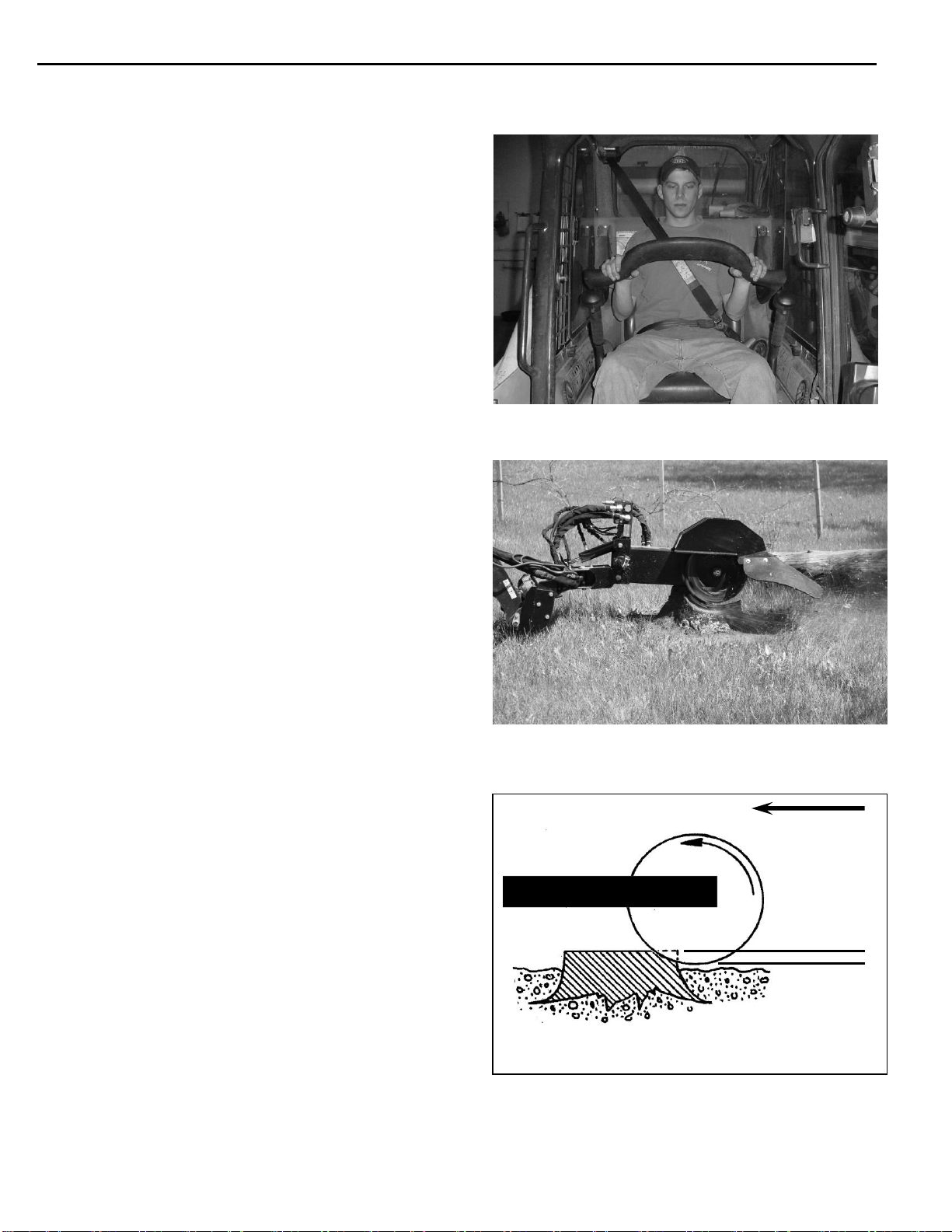
This attachment is designed to be used for
grinding stumps from just above ground level
to below ground level. NEVER use this
machine for any other purpose.
Read the operator’s manual for the “Skid Steer
Loader.” NEVER allow untrained people to
operate.
Operating instructions must be given to everyone
before operating this attachment and at least
once a year thereafter in accordance with OSHA
regulations.
NEVER exceed the maximum recommended
input power or speed specifications for the
attachment. Over-powering or over-speeding the
attachment may cause personal injury and/or
machine damage.
The Mini Stump Grinder is not designed to be
used on a loader with a Rated Operating
Capacity (ROC) of more than 1000 lbs.
Keep all shields, guards, and covers in place.
Do not modify equipment or add attachments that
are not approved by Erskine Attachments LLC.
Use adequate safety warning lights and devices
as required by local regulations. Obey all local
laws and regulations regarding machine
operation on public property. Always call before
you dig (1-888-258-0808). When you call, you
will be directed to a location in your state/city for
information about buried lines (electric,
telephone, cable TV, water, sewer, gas, etc.).
Operation
Always wear eye protection that meets z87.1 or
use with a loader enclosure that provides similar
protection.
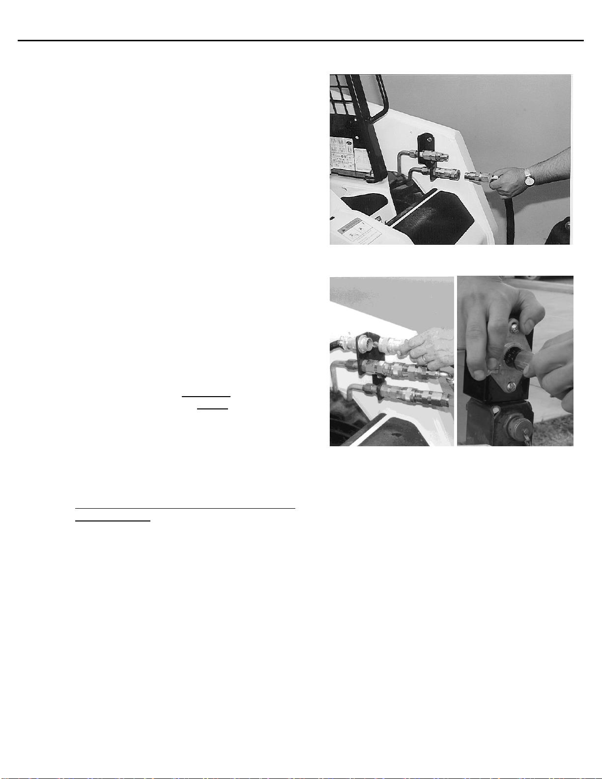
Hydraulic connections may be hot after use. Use
gloves if connecting or disconnecting after use.
Check and be sure all operating controls are in
neutral before starting the engine.
Operation (continued)
Keep people away from loader, attachment and
discharge when in use. This attachment sends
objects flying and has rotating parts. NEVER
direct discharge toward people –rocks and debris
can be thrown.
NEVER operate near embankments or terrain
that is so steep that rollover could occur.
Always stay in the operator position when using
the attachment. If you are using a walk-behind
loader, stay behind the loader at the controls
while operating.
Before leaving the operators position, disengage
hydraulic drive, lower the attachment to rest flat
on the ground, stop engine, set park brake, and
wait for all motion to stop.
NEVER place hands in the discharge area or
clear debris while the engine is running.
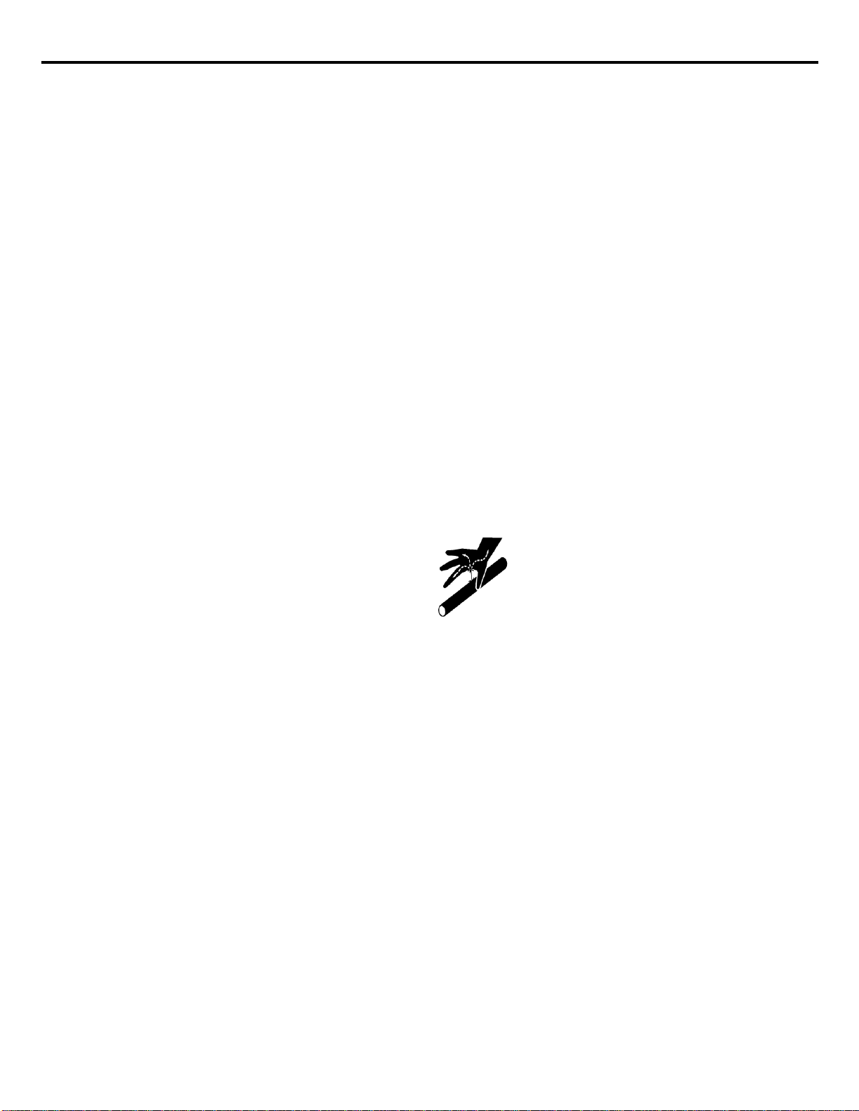
Avoid High Pressure Fluids Hazard
Escaping fluid under pressure can
penetrate the skin causing serious
injury.
Avoid the hazard by relieving the
pressure before disconnecting
hydraulic lines.
Use a piece of paper or cardboard, NOT BODY
PARTS, to check for suspected leaks. Wear
protective gloves and safety glasses or goggles
when servicing or performing maintenance on
hydraulic systems.
If an accident occurs, see a doctor immediately.
Any fluid injected into the skin must be
surgically removed within a few hours or
gangrene may result.
Maintenance
NEVER make adjustments, lubricate, clean, or
perform any service on the machine while it is in
operation.
Make sure the attachment is serviced on a daily
basis. Improper maintenance can cause
serious injury or death in addition to damage to
the attachment and/or your equipment.

5
SERIAL NUMBER AND SAFETY DECAL LOCATIONS
Serial Number Location:
It is important to refer to the serial number of the attachment when making repairs or ordering parts. Early or
later models (identification made by serial number) may use different parts, or it may be necessary to use
different procedures in doing a specific operation.
Serial Plate
Mini Brand Decal
B
D
C
A
C
B
E

6
Safety Decals Locations:
The locations of the safety decals are shown. If these
decals are missing, damaged, or painted over they
must be replaced. Call Erskine Attachments LLC (218-
435-4045) for replacement decals.
A
Part number: 203234
Location: On either side of the cutter shield
Quantity: 2
C
B
Part number: 316078
Location: On right side of swing frame
Quantity: 1
Part number: 320025
Location: On either side of cutter shield
Quantity: 2
Part number: 200001
Location: On front of swing frame near valve block
Quantity: 1
SERIAL NUMBER AND SAFETY DECAL LOCATIONS________
Mini Brand Decal
Location: On either side of the cutter shield
Quantity: 2
D
E
Part number: 201415
Location: On coupler shield
Quantity: 1

7
USER’S INSTRUCTIONS FOR MOUNTING THE MINI STUMP GRINDER
After uncrating the attachment, use the following procedure to mount the attachment to the loader.
Mounting to a ride-on mini skid
loader:
1. Use the step, safety treads, and grab
handles to get on and off the loader.
2. Sitting in the operator’s seat, lower seat
bar, fasten the seat belt and with the
controls in a neutral position, start the
engine.
3. Drive the loader to the rear of the
attachment. Put the loader quick attach
coupler into the attachment mounting
bracket.
4. Tilt the loader coupler backward a small
amount until it is fully engaged in the
attachment mounting bracket.
5. Stop the engine and engage the park
brake.
6. Exit the loader and secure the coupler
locking mechanism that locks the
attachment to the loader.
Mounting to a walk-behind mini skid
loader:
1. Standing at the operator’s station with the
controls in a neutral position, start the
engine.
2. Drive the loader to the rear of the
attachment. Put the loader quick attach
coupler into the attachment mounting
bracket.
3. Tilt the loader coupler backward a small
amount until it is fully engaged in the
attachment mounting bracket.
4. Stop the engine and engage the park
brake.
5. Walk to the front of the loader and secure
the coupler locking mechanism that locks
the attachment to the loader.
Coupler wedges or pins must extend through the holes in the attachment
mounting plate. Levers must be fully down and locked. Failure to secure wedges or pins
can allow attachment to come off and cause injury or death.

8
Attaching Hydraulics:
1. Connect the hydraulic quick couplers from the
attachment to the loader.
IMPORTANT: Make sure the quick couplers
are fully engaged. If the quick couplers do
not fully engage, check to see that the
couplers are the same size and brand. Do
not force the quick couplers together.
IMPORTANT: Wipe the ends of the hydraulic
quick couplers (both lead and loader) with a
rag to remove any possible contamination.
Contamination can cause hydraulic
components to fail and is not covered under
warranty.
2. Connect the attachment wire harness to the
loader wire harness receptacle.
3. Make sure the hoses are properly routed to fit
your specific loader. If the hoses are not
routed correctly, hoses may get pinched or
rub on tires. Be sure to check the hose
routing through the full range of intended
motion of the attachment before operating it.
More than one routing may be acceptable
depending on the loader. Pick the routing
that best suits your loader.
IMPORTANT: Proper hose routing is the
responsibility of the owner and/or operator.
Pinched or stretched hoses are not covered
under warranty.
Mounting is now complete and you are ready to
use the stump grinder. Use reverse order of
above instructions to dismount the stump grinder
from the loader.
USER’S INSTRUCTIONS FOR MOUNTING THE MINI STUMP GRINDER
NOTE: Attachment is shipped with 12FJX (1-1/16”
Female JIC Swivel) fittings on the ends of the lead
hoses.

9
OPERATING INSTRUCTIONS
Hydraulic Controls
All functions can be activated by the steering
lever switches on the loader (if loader is
equipped), or with the pistol grip control harness.
NOTE: Your loader must have the attachment
control kit installed to make use of the lever
switches.
The previously installed pistol grip allows the
operator to engage all functions (see Set-Up
Assembly).
FUNCTIONS ARE ACTIVATED AS FOLLOWS:
(A) Button 1 moves grinder arm UP.
(B) Button 2 moves grinder arm DOWN.
(C) Button 3 swings grinder arm LEFT.
(D) Button 4 swings grinder arm RIGHT.
NOTE: For steering lever functions, refer to your
loader’s operator’s manual.

10
OPERATING INSTRUCTIONS
.
Operation
1. With the operator in the operating position, start
the engine.
2. For proper operation of the attachment, try to
approach the stump from a position that will
allow the loader to sit as level as possible.
Remember to position the grinder so that wood
chips and debris will be thrown in a safe
direction.
3. Swing the attachment all the way to the right
side.
4. Position the loader so the attachment is on the
far right side of the stump. Lift the attachment
slightly above and to the right from the far side
of the stump.
5. Fully lower the loader’s boom arms and use the
loader’s tilt to get the pivot arm plum, this will
ensure the grinder cuts level.
6. Engage the hydraulics on the loader, increase
the throttle to maximum speed, and using the
controls, lower the cutting wheel into the stump.
NOTE: Rate of cut will be determined by the
condition of the teeth, type of tree, and
condition the stump is in.
NOTE: Only cut approximately 1 to 2 inches of
stump depth at a time.
IMPORTANT: Do not move backward into the
stump while the grinder arm is in motion. Doing
so may result in vibration and/or damage to the
motor.
1 to 2 inches
First Cut
Direction of Loader
travel between cuts

11
OPERATING INSTRUCTIONS
.
7. Once the attachment has started cutting,
engage the control to start the grinder arm
swinging.
NOTE: The arm senses the difficulty of the
cut and will automatically adjust the travel
speed.
8. When the attachment has completed a pass,
move the loader rearward about 1-1/2” and
engage the control to cut back across in the
opposite direction.
9. Continue until a completed layer of the stump
has been ground off and then repeat the
procedure starting again at the front of the
stump.
10. The next cuts will be performed to take the
stump below ground level, if wanted.
When cutting below grade
you may be more likely to throw rocks or
other debris. To avoid injury or death,
never direct discharge toward people.
11. Follow the same procedures as cutting
above ground level, with the addition of
inspecting the area thoroughly for large
rocks/debris that may damage the
attachment.
Final Cut
1 to 2 inches
Direction of Loader
travel between cuts
Final Cut
NOTE: Shown after a series of 1 to 2 inch deep cuts.
Direction of Loader
travel between cuts

12
_____________________ROUTINE MAINTENANCE________________
Lower the stump grinder to rest on the ground, shut down the engine, relieve the
hydraulic pressure to the attachment, wait for all motion to stop, and set park brake before leaving
the operator’s position to perform service of any kind.
It is the operator’s responsibility to make daily inspections of the loader and attachment for damage, loose
bolts, fluid leaks, or anything else that could cause a potential service or safety problem. Preventive
maintenance is the easiest and least expensive type of maintenance.
IMPORTANT: Bolts and set screws can loosen after initial usage. After the first hour of operation check all
bolts and set screws.
Use No. 2 lithium base gun grease when
lubricating all of the attachment’s grease fittings.
Grease the attachment Arm Pivot Bushing zerk [A]
and the Swing Arm Pivot Bushing [B].
Grease all bushings once after every 8 hours of
operation.
8
LUBRICATION
[A]
[B]
No. 2 Lithium
base gun grease

13
ROUTINE MAINTENANCE
Grease the swing cylinder bushings after every 8
hours of operation.
Grease the lift cylinder pins after every 8 hours of
operation.
Check the oil level in the gearbox at least once
per year. The gearbox should be approximately
1/3 full. If it is too full, oil may seep out of the
breather/fill plug.
Change the oil at least once every three years.
Use 80-90 gear lube. Gearbox oil capacity is
approximately 32 ounces.
LUBRICATION (continued)
8
8
GEARBOX OIL LEVEL

14
ROUTINE MAINTENANCE
1. With the attachment on a flat level surface,
lift up the swing arm (using a jack or a
hoist) and brace with jack stands or blocks
in a lifted position. Make sure the
mounting plate stays flat on the ground.
2. Remove the (2) bolts holding on the shield.
3. Loosen the (2) bolts that hold each tooth
holder in place, until the tooth can be
removed. Remove the tooth.
4. Use reverse order to put in new teeth.
5. Stagger the teeth as shown in the drawing.
NOTE: Torque the holder bolt to 200 ft/lbs.
TEETH REMOVAL AND REPLACEMENT
Photo unavailable at press
time.
Photo unavailable at press
time.

15
SET UP ASSEMBLY OF THE GENERIC CONTROL HANDLE HARNESS
NOTE: If the loader is equipped with an
Attachment Control package, the appropriate
harness should be installed from the factory.
Mounting the generic control handle wire harness
will vary from loader to loader. Use these
instructions as a general guide. You may need to
drill holes to mount pieces of this harness.
Mounting hardware is not included.
1. Mount the wire harness receptacle to the
loader arm near the hydraulic quick couplers.
2. Route the wire harness back along the loader
arms and fasten with cable ties.
3. Open the rear door to access the battery
compartment. Pull the excess wire into the
engine compartment. Secure it with plastic tie-
wraps.
4. Connect the red fused wire to the positive (+)
battery terminal or to a suitable accessory wire
with a minimum rating of 5 amps.
5. Connect the black wire to the negative (-)
battery terminal or to a frame ground.
6. Connect the control handle connector to the
main harness connector.
7. Mount the control handle in a convenient
location near the operator’s station.
NOTE: Secure the wiring harness in place
with plastic cable ties, making sure it is clear of
extra hot areas or any moving parts on the
engine or loader. Pinched, stretched, or
melted wiring harnesses are not covered under
warranty.
8. Close the rear door.
NOTE: Be sure the harness is properly
positioned to prevent pinching when closing
the door.

16
PARTS INFORMATION
ITEM
QTY
PART NO.
DESCRIPTION
STOCK NO.
1
1
400600
GRINDER MOUNT MINI W/A
2
1
400601
FRAME SWING MINI SG W/A
3
1
400602
FRAME ARM MINI SG W/A
4
1
400604
WHEEL GRINDER 16 ASSM
5
1
400605
SHIELD MINI STUMP GRINDER W/A
6
1
311657
SHIELD RUBBER
7
1
310198
PIN 1.00 X 7.63 W/A
8
1
311605
PIN 1.25 X 6.75 W/A
9
1
313460
PIN 1.00 X 2.75 W/A
10
1
400041
PIN 1 X 4 W/A
11
1
316026
PIN 1 X 5 W/A
12
1
314079
PIN 1.25 X 5.50 W/H Z
13
1
400633
SHEILD COUPLER MSG PAINTED
15
1
13214
BOLT HEX
1/2 X 2-3/4 NC GR 5
14
1
314120
GEARBOX RC51 PNT (32oz of 80W-90)
18
1
314015
COUPLER BM 1.25 X 1.38
19
15
37212
NUT HEX LOCK
3/8 NC
20
7
103116
BOLT HEX
3/8 X 1 NC GR 5
23
7
33220
WASHER FENDER
3/8 X 1 1/2
24
7
13107
BOLT HEX
3/8 X 1-1/4 NC GR 5
25
2
13207
BOLT HEX
1/2 X 1-1/4 NC GR 5
26
2
0167011
NUT FLG TOP-LOCK
1/2 GR8
27
3
37214
NUT HEX LOCK
1/2 NC
28
2
22888
BOLT FLNG 12PT
1/2 X 1-3/4 NC GR 9
29
1
13113
BOLT HEX
3/8 X 2-1/2 NC GR 5
30
4
13309
BOLT HEX
5/8 X 1-1/2 NC GR 5
31
4
37216
NUT HEX LOCK
5/8 NC
32
12
311629
TOOTH HOLDER SG BLANK
33
12
311626
TOOTH SG RIGHT
34
12
311627
TOOTH SG LEFT
35
12
311677
TOOTH HOLDER SG THREADED
36
24
311630
BOLT SOCKET HEAD CAP SCREW
5/8 X 2-1/4 NF
37
1
400000
MOUNT FRAME TORO MINI W/A
OPTIONAL MOUNT PACKAGE
1
400001
MOUNT FRAME ASV MINI W/A
OPTIONAL MOUNT PACKAGE
1
400002
MOUNT FRAME BC MINI W/A
OPTIONAL MOUNT PACKAGE
1
300283
MOUNT FRAME UNIV MINI W/A
OPTIONAL MOUNT PACKAGE
1
330622
MOUNT FRAME AVANT MINI W/A
AVANT ADPT MNT PKG 330753
38
6
15209
BOLT HEX 1/2 X 1-1/2 NC GR 8
MOUNTING PACKAGES
39
6
0167011
NUT FLG TOP LOCK 1/2 NC GR 8 YZ
MOUNTING PACKAGES

17
PARTS INFORMATION

18
PARTS INFORMATION
ITEM
QTY
PART NO.
DESCRIPTION
STOCK NO.
13
1
311659
VALVE ASSM STUMP GRINDER
15
1
400074
CYLINDER 2 X 4 W/BUSHINGS
16
1
400015
CYLINDER 2.5 X 6 W/BUSHINGS
17
1
300694
MOTOR HYD 6.2
21
2
13071
BOLT HEX
5/16 X 4-1/2 NC GR 5
22
2
37211
NUT HEX LOCK
5/16 NC
32
2
320089
ADPT ELB 8MB-6MJ-90
33
2
201852
ADPT STR 10MB-10MJ
34
2
201851
ADPT STR 12MB-10MJ
35
2
300215
ADPT ELB 12MB-10MJ-90
36
2
400626
HOSE 1/4 X 17 SMB-6FJX
(CYL.BASE TO TOP PORT (B1))
37
2
201925
ADPT STR 8MB-6MJ
38
2
400627
HOSE 5/8 X 21 10FJX-10FJX
MOTOR TO VALVE
39
2
400628
HOSE 5/8 X 60 12FJX-10JFX
LEAD
40
1
400625
HOSE 1/4 X 31 6MB-6FJX
(CYL. ROD TO TOP PORT)
41
1
400624
HOSE 1/4 X 35 6MB-6FJX
(CYL. BASE TO BOTTOM PORT)

19
PARTS INFORMATION
3
2
4
1
1
315128
PKG HRN - FUNC CONTROL
1
1
315110
PISTOL GRIP ASSM ALL
2
1
315126
HRN LOADER GENERIC
3
1
300247
BRKT WR HRN GEN MINI PNT
4
1
315127
HRN BLOWER GENERIC
OPTIONAL WIRE HARNESSES (NOT SHOWN)
315090
HRN 14 PIN COMMON
Bobcat® Loaders
315152
HRN 14 PIN CASE/NH
Case® & New Holland® Loaders
320084
PKG HRN 14-PIN
JOHN DEER LOADERS
200008
HRN 8 PIN CAT A
Caterpillar® A series Loaders
315153
HRN 8 PIN ASV
ASV® Loaders
315339
HRN 8 PIN CAT B/C
Caterpillar® B series High-Flow Loaders

20
GENERAL SPECIFICATIONS
Model
Drive System
Hydraulic with Gearbox
Hydraulic Requirements
7 to 14 GPM
Maximum Cutting Diameter
36”
Maximum Cutting Depth
6” below ground
Cutting Arc
66°
Cutting Wheel Diameter
Approx. 18”
Cutting Wheel Speed
500 to 1000 RPM
Operating Weight
395#
All dimensions are in INCHES.
Table of contents
Other Erskine Attachments Tractor Accessories manuals
Popular Tractor Accessories manuals by other brands

Toro
Toro Greensmaster 04654 Series Operator's manual

Black Widow
Black Widow ATV-RAKE-2143 instructions

BROWNS
BROWNS BALE HANDLER Owners Illustrated Instruction Book & Parts List

MK Martin
MK Martin 3200 Operator's & parts manual

Avantco
Avantco A36588 Operator's manual for Attachment

Toro
Toro Wheel Horse 79361 Operator's manual