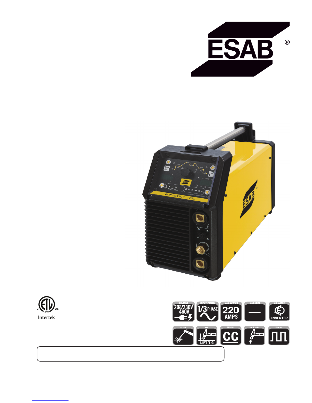
ESAB ET 220i AC/DC User manual

ESAB ET 220i AC/DC
Art # A-12839_AB
Operating
Manual
4010062
Révision : AD Issue Date: October 26, 2016 Manual No.: 0-5346
esab.com
HF START
HF
PULSE
CURRENT
AC
DC

WE APPRECIATE YOUR BUSINESS!
Congratulations on your new ESAB product. We are proud to have you as our customer and will
strive to provide you with the best service and reliability in the industry. This product is backed by
our extensive warranty and world-wide service network. To locate your nearest distributor or service
agency, visit us on the web at www.esab.com
This Operating Manual has been designed to instruct you on the correct use and operation of your
ESAB product. Your satisfaction with this product and its safe operation is our ultimate concern.
Therefore please take the time to read the entire manual, especially the Safety Precautions. They
will help you to avoid potential hazards that may exist when working with this product.
YOU ARE IN GOOD COMPANY!
The Brand of Choice for Contractors and Fabricators Worldwide.
ESAB is a Global Brand of Welding Products.
We distinguish ourselves from our competition through market-leading, dependable products that
have stood the test of time. We pride ourselves on technical innovation, competitive prices, excel-
lent delivery, superior customer service and technical support, together with excellence in sales
and marketing expertise.
Above all, we are committed to developing technologically advanced products to achieve a safer
working environment within the welding industry.

!
WARNING
Read and understand this entire Manual and your employer’s safety practices before installing, operating, or
servicing the equipment.
While the information contained in this Manual represents the Manufacturer's best judgement, the Manufac-
turer assumes no liability for its use.
i
Welding Power Supply
Operating Manual Number 0-5346 for:
ESAB ET 220i AC/DC Power Source Part Number W1009300
Published by:
ESAB
2800 Airport Rd.
Denton, Texas 76207
www.esab.com
Copyright © 2015 by
ESAB
All rights reserved.
Reproduction of this work, in whole or in part, without written permission of the publisher
is prohibited.
The publisher does not assume and hereby disclaims any liability to any party for any loss
or damage caused by any error or omission in this Manual, whether such error results from
negligence, accident, or any other cause.
Publication Date: May 7, 2015
Revision Date: October 26, 2016
Record the following information for Warranty purposes:
Where Purchased: ____________________________________
Purchase Date: ____________________________________
Equipment Serial #: ____________________________________

Be sure this information reaches the operator.
You can get extra copies through your supplier.
CAUTION
These INSTRUCTIONS are for experienced operators. If you are not fully familiar with
the principles of operation and safe practices for arc welding and cutting equipment,
we urge you to read our booklet, “Precautions and Safe Practices for Arc Welding, Cut-
ting, and Gouging,” Form 0-5407. Do NOT permit untrained persons to install, operate,
or maintain this equipment. Do NOT attempt to install or operate this equipment until
you have read and fully understand these instructions. If you do not fully understand
these instructions, contact your supplier for further information. Be sure to read the
Safety Precautions before installing or operating this equipment.
USER RESPONSIBILITY
This equipment will perform in conformity with the description thereof contained in this manual and accompany-
ing labels and/or inserts when installed, operated, maintained and repaired in accordance with the instructions
provided. This equipment must be checked periodically. Malfunctioning or poorly maintained equipment should
not be used. Parts that are broken, missing, worn, distorted or contaminated should be replaced immediately.
Should such repair or replacement become necessary, the manufacturer recommends that a telephone or written
request for service advice be made to the Authorized Distributor from whom it was purchased.
This equipment or any of its parts should not be altered without the prior written approval of the manufacturer. The
user of this equipment shall have the sole responsibility for any malfunction which results from improper use, faulty
maintenance, damage, improper repair or alteration by anyone other than the manufacturer or a service facility
designated by the manufacturer.
!
READ AND UNDERSTAND THE INSTRUCTION MANUAL BEFORE INSTALLING OR
OPERATING.
PROTECT YOURSELF AND OTHERS!

TABLE OF CONTENTS
SECTION 1: SAFETY........................................................................................ 1-1
1.0 Safety Precautions.......................................................................................... 1-1
SECTION 2:
INTRODUCTION ..................................................................................... 2-1
2.01 How To Use This Manual ................................................................................ 2-1
2.02 Equipment Identification ................................................................................. 2-1
2.03 Receipt of Equipment...................................................................................... 2-1
2.04 Description ..................................................................................................... 2-1
2.05 User Responsibility......................................................................................... 2-1
2.06 Transporting Methods..................................................................................... 2-2
2.07 Packaged Items .............................................................................................. 2-2
2.08 Duty Cycle....................................................................................................... 2-2
2.09 Specifications ................................................................................................. 2-3
2.10 Optional Accessories ...................................................................................... 2-4
SECTION 3:
INSTALLATION, OPERATION AND SETUP ........................................................ 3-1
3.01 Environment ................................................................................................... 3-1
3.02 Location.......................................................................................................... 3-1
3.03 Ventilation....................................................................................................... 3-1
3.04 Mains Supply Voltage Requirements .............................................................. 3-1
3.05 High Frequency Introduction .......................................................................... 3-2
3.06 High Frequency Interference........................................................................... 3-2
3.07 Electromagnetic Compatibility ........................................................................ 3-3
3.08 Power Source Controls, Indicators and Features ............................................ 3-4
3.09 Setup for TIG (GTAW) Welding ..................................................................... 3-10
3.10 TIG (GTAW) Programming Mode ................................................................. 3-13
3.11 TIG (GTAW) Welding Secondary Parameters ............................................... 3-18
3.12 GTAW Spot Welding Mode with DWELL Time (Stitch Mode)........................ 3-19
3.13 Tip Tronic Operation...................................................................................... 3-20
3.14 Setup for Stick (SMAW) Welding ................................................................ 3-22
3.15 Stick (SMAW) Programming Mode............................................................... 3-23
3.16 User Specific Menus..................................................................................... 3-26
3.17 Special Function ........................................................................................... 3-27
3.18 Shielding Gas Regulator/ Flowmeter Operating Instructions......................... 3-30
3.19 Foot Control, Part No. W4013200 (Optional Accessory) .............................. 3-32
SECTION 4:
BASIC WELDING GUIDE ............................................................................ 4-1
4.01 Stick (SMAW) Basic Welding Technique ......................................................... 4-1
4.02 Stick (SMAW) Welding Troubleshooting......................................................... 4-8
4.03 TIG (GTAW) Basic Welding Technique .......................................................... 4-11
4.04 TIG (GTAW) Welding Problems..................................................................... 4-13

TABLE OF CONTENTS
SECTION 5:
POWER SOURCE PROBLEMS AND ROUTINE SERVICE REQUIREMENTS .................... 5-1
5.01 Basic Troubleshooting .................................................................................... 5-1
5.02 Power Source Problems ................................................................................. 5-3
5.03 Routine Service and Calibration Requirements............................................... 5-4
5.04 Cleaning the Welding Power Source ............................................................... 5-5
SECTION 6:
KEY SPARE PARTS................................................................................... 6-1
6.01 Key Spare Parts .............................................................................................. 6-2
APPENDIX A: CIRCUIT DIAGRAM OF ET 220i AC/DC.................................................. A-1
REVISION HISTORY ........................................................................................ A-2

ET 220I AC/DC
Manual 0-5346 SAFETY 1-1
1.0 Safety Precautions
Users of ESAB welding and plasma cutting equipment have the ultimate responsibility for ensuring that
anyone who works on or near the equipment observes all the relevant safety precautions. Safety precautions
must meet the requirements that apply to this type of welding or plasma cutting equipment. The following
recommendations should be observed in addition to the standard regulations that apply to the workplace.
All work must be carried out by trained personnel well acquainted with the operation of the welding or plasma
cutting equipment. Incorrect operation of the equipment may lead to hazardous situations which can result in
injury to the operator and damage to the equipment.
1. Anyone who uses welding or plasma cutting equipment must be familiar with:
- its operation
- location of emergency stops
- its function
-
relevant safety precautions
- welding and / or plasma cutting
2. The operator must ensure that:
- no unauthorized person stationed within the working area of the equipment when it is started up.
- no one is unprotected when the arc is struck.
3. The workplace must:
- be suitable for the purpose
- be free from drafts
4. Personal safety equipment:
- Always wear recommended personal safety equipment, such as safety glasses, ame proof
clothing, safety gloves.
- Do not wear loose tting items, such as scarves, bracelets, rings, etc., which could become
trapped or cause burns.
5. General precautions:
- Make sure the return cable is connected securely.
- Work on high voltage equipment may only be carried out by a qualied electrician.
- Appropriate re extinguishing equipment must be clearly marked and close at hand.
- Lubrication and maintenance must not be carried out on the equipment during operation.
Dispose of electronic equipment at the recycling facility!
In observance of European Directive 2002/96/EC on Waste Electrical and Electronic Equipment and its implementation in ac-
cordance with national law, electrical and/or electronic equipment that has reached the end of its life must be disposed of at a
recycling facility.
As the person responsible for the equipment, it is your responsibility to obtain information on approved collection stations.
For further information contact the nearest ESAB dealer.
ESAB can provide you with all necessary welding protection and accessories.
SECTION 1: SAFETY

ET 220I AC/DC
SAFETY Manual 0-5346
1-2
Arc welding and cutting can be injurious to yourself and others. Take
precautions when welding and cutting. Ask for your employer's safety
practices which should be based on manufacturers' hazard data.
ELECTRIC SHOCK - Can kill.
- Install and earth (ground) the welding or plasma cutting unit in accordance with applicable standards.
- Do not touch live electrical parts or electrodes with bare skin, wet gloves or wet clothing.
- Insulate yourself from earth and the workpiece.
- Ensure your working stance is safe.
FUMES AND GASES - Can be dangerous to health.
- Keep your head out of the fumes.
- Use ventilation, extraction at the arc, or both, to take fumes and gases away from your breathing zone
and the general area.
ARC RAYS - Can injure eyes and burn skin.
- Protect your eyes and body. Use the correct welding / plasma cutting screen and lter lens and wear
protective clothing.
- Protect bystanders with suitable screens or curtains.
FIRE HAZARD
- Sparks (spatter) can cause re. Make sure therefore that there are no inammable materials nearby.
NOISE - Excessive noise can damage hearing.
- Protect your ears. Use earmus or other hearing protection.
- Warn bystanders of the risk.
MALFUNCTION - Call for expert assistance in the event of malfunction.
READ AND UNDERSTAND THE INSTRUCTION MANUAL BEFORE INSTALLING OR OPERATING.
PROTECT YOURSELF AND OTHERS!
WARNING
This product is solely intended for welding. Any other use may result in
personal injury and / or equipment damage.
CAUTION
Class A equipment is not intended for use in residential
locations where the electrical power is provided by the
public low-voltage supply system. There may be poten-
tial diculties in ensuring electromagnetic compatibility
of class A equipment in those locations, due to conducted
as well as radiated disturbances.
CAUTION
Read and understand the instruction manual before
installing or operating.
CAUTION
Do not use the power source for thawing frozen pipes.
WARNING
!

ET 220I AC/DC
Manual 0-5346 INTRODUCTION 2-1
SECTION 2:
INTRODUCTION
2.03 Receipt of Equipment
When you receive the equipment, check it against the invoice to
make sure it is complete and inspect the equipment for pos-
sible damage due to shipping. If there is any damage, notify the
carrier immediately to file a claim. Furnish complete information
concerning damage claims or shipping errors to the location in
your area listed in the inside back cover of this manual.
Include all equipment identification numbers as described above
along with a full description of the parts in error.
Move the equipment to the installation site before un-crating
the unit. Use care to avoid damaging the equipment when using
bars, hammers, etc., to un-crate the unit.
2.01 How To Use This Manual
To ensure safe operation, read the entire manual, including the
chapter on safety instructions and warnings.
Throughout this manual, the words WARNING,
CAUTION, and NOTE may appear. Pay particular attention to the
information provided under these headings. These special an-
notations are easily recognized as follows:
NOTE!
An operation, procedure, or background
information which requires additional
emphasis or is helpful in efficient operation
of the system.
!
CAUTION
A procedure which, if not properly followed,
may cause damage to the equipment.
!
WARNING
A procedure which, if not properly followed,
may cause injury to the operator or others
in the operating area.
WARNING
Gives information regarding possible electri-
cal shock injury. Warnings will be enclosed
in a box such as this.
You will also notice other icons appearing throughout the manual.
These are to advise you of specific types of hazards or cautions
related to the portion of information that follows. Some may have
multiple hazards that apply and would look something like this:
!
2.02 Equipment Identification
The unit’s identification number (specification or part number),
model, and serial number usually appear on a nameplate at-
tached to the control panel. In some cases, the nameplate may
be attached to the rear panel. Equipment which does not have
a control panel such as gun and cable assemblies is identified
only by the specification or part number printed on the shipping
container. Record these numbers on the bottom of page ii for
future reference.
2.04 Description
The ET 220i AC/DC is light weight constant current welding
power sources incorporating the latest digital inverter technol-
ogy to provide exceptional AC/DC arc characteristics, TIG welding
features include torch trigger latch, pre & post flow gas control,
pulse control, spot weld control, hot start control, up & down
slope control. Liftarc TIG and HF TIG operating modes are avail-
able.
This unit also has outstanding arc characteristics across a wide
range of Manual Metal Arc Welding (SMAW) electrodes. SMAW
welding features, hot start control and arc force control. The units
are equipped with digital amperage and voltage meters. The unit
are also fully compliant to European Standard EN 60974-1 and
IEC 60974.1.
The ET 220i AC/DC provide excellent welding performance
across a broad range of applications when used with the correct
welding consumables and procedures. The following instructions
detail how to correctly and safely set up the machine and give
guidelines on gaining the best efficiency and quality from the
Power Source. Please read these instructions thoroughly before
using the unit.
2.05 User Responsibility
This equipment will perform as per the information contained
herein when installed, operated, maintained and repaired in
accordance with the instructions provided. This equipment must
be checked periodically. Defective equipment (including welding
leads) should not be used. Parts that are broken, missing, plainly
worn, distorted or contaminated, should be replaced immediately.
Should such repairs or replacements become necessary, it is
recommended that such repairs be carried out by appropriately
qualified persons approved by ESAB. Advice in this regard can be
obtained by contacting an Accredited ESAB Distributor.
This equipment or any of its parts should not be altered from
standard specification without prior written approval of ESAB.
The user of this equipment shall have the sole responsibility for
any malfunction which results from improper use or unauthorized
modification from standard specification, faulty maintenance,
damage or improper repair by anyone other than appropriately
qualified persons approved by ESAB.

ET 220I AC/DC
INTRODUCTION Manual 0-5346
2-2
2.06 Transporting Methods
!
WARNING
Disconnect input power conductors from de-energized supply line before moving the welding
Power Source.
Lift Power Source with handle on top of case. Use handcart or similar device of adequate ca-
pacity. If using a fork lift vehicle, secure the Power Source on a proper skid before transporting.
2.07 Packaged Items
ET 220i AC/DC Inverter Power Source (Part No. W1009300)
• ET 220i AC/DC Inverter Power Source
• Two male 50mm Dinse connectors
• Operating Manual
2.08 Duty Cycle
The rated duty cycle of a Welding Power Source, is a statement of the time it may be operated at its rated welding current output with-
out exceeding the temperature limits of the insulation of the component parts. To explain the 10 minute duty cycle period the follow-
ing example is used. Suppose a Welding Power Source is designed to operate at a 40% duty cycle, 170 amperes at 26.8 volts. This
means that it has been designed and built to provide the rated amperage (170A) for 4 minutes, i.e. arc welding time, out of every 10
minute period (40% of 10 minutes is 4 minutes). During the other 6 minutes of the 10 minute period the Welding Power Source must
idle and be allowed to cool. The thermal cut out will operate if the duty cycle is exceeded.
Art # A-12840
ET 220i AC/DC
SMAW (STICK) GTAW (TIG)
SAFE OPERATING REGION
(TIG & STICK)
Figure 2-1: ET 220i AC/DC Duty Cycle

ET 220I AC/DC
Manual 0-5346 INTRODUCTION 2-3
2.09 Specifications
Description ET 220i AC/DC
Power Source Part Number W1009300
Power Source Mass 29.5lbs (13.4Kg) without power cable
Power Source Dimensions H13" x W7.25" x D19"
(H326mm x W185mm x D483mm)
Cooling Fan Cooled
Welder Type Inverter Power Source
Standards CSA E60974-1, ANSI/IEC 60974-1
Number of Phases 1/3 phase
Nominal Supply Voltage 208-230/460VAC (1 phase)
+/-15%
208-230/460VAC (3 phase)
+/-15%
Nominal Supply Frequency 50/60Hz
Welding Current Range (Stick Mode) 10 – 150A (1 phase) 10 – 170A (3 phase)
Welding Current Range (TIG Mode) 5 - 200A (1 phase) 5 - 220A (3 phase)
Effective Input Current (I1eff) (note2) 27.6A (208V, 1 phase)
25.0A (230V, 1 phase)
15.2A (460V, 1 phase)
16.8A (208V, 3 phase)
15.2A (230V, 3 phase)
8.2A (460V, 3 phase)
Maximum Input Current (I1max)37.3A (208V, 1 phase)
33.7A (230V, 1 phase)
18.1A (460V, 1 phase)
24.5A (208V, 3 phase)
22.1A (230V, 3 phase)
11.9A (460V, 3 phase)
Generator Requirement (note4) 13kW (16kVA @ 0.8PF)
Stick (SMAW)
Welding Output, 40ºC, 10 min.
150A @ 40%, 26.0V (1 phase)
140A @ 60%, 25.6V (1 phase)
120A @ 100%, 24.8V (1 phase)
170A @ 40%, 26.8V (3 phase)
140A @ 60%, 25.6V (3 phase)
120A @ 100%, 24.8V (3 phase)
TIG (GTAW)
Welding Output, 40ºC, 10 min.
200A@45%, 18.8V (1 phase)
180A@60%, 17.2V (1 phase)
160A@100%, 16.4V (1 phase)
220A @ 40%, 18.8V (3 phase)
180A @ 60%, 17.2V (3 phase)
160A @ 100%, 16.4V (3 phase)
Open Circuit Voltage (VRD active) <113V
Protection Class IP23S
Table 2-1: Power Source Specification

ET 220I AC/DC
INTRODUCTION Manual 0-5346
2-4
NOTE!
Note 1:Due to variations that can occur in manufactured products, claimed performance, voltages, ratings,
all capacities, measurements, dimensions and weights quoted are approximate only. Achievable capacities
and ratings in use and operation will depend upon correct installation, use, applications, maintenance and
service.
Note 2: The Effective Input Current should be used for the determination of cable size & supply require-
ments.
Note 3: Motor start fuses or thermal circuit breakers are recommended for this application. Check local
requirements for your situation in this regard.
Note 4: Generator Requirements at the Maximum Output Duty Cycle.
Due to large variations in performance and specifications of different brands and types of generators, ESAB
cannot guarantee full welding output power or duty cycle on every brand or type of generator.
ESAB recommends that when selecting a generator, that the particular power source / generator combina-
tion be adequately trialled to ensure the combination performs to the users expectations.
Note 5: ESAB reserves the right to change product performance and specifications without notice.
2.10 Optional Accessories
Part Number Description
W4014604 Tig Torch 26F with 4m lead and remote control
BGSAK2 TIG Torch accessory kit
W4013200 Foot Control with 8m lead
646757 Electrode Holder & Work Lead Set 5m 400A 50mm DINSE
646325 Electrode Holder & Work Lead Set 8m 400A 50mm DINSE
646763 Electrode Holder w / Deadman Switch & Work Lead Set 8m 400A 50mm DINSE
301526 Comet Edge Argon Regulator / Flowmeter
704461 50mm Male DINSE cable connector
W7004913 Shielding Gas Hose Assembly
W4001302 CU-6 (400V) Water Cooling Unit
W4001350 Cable Protection (CU-6)
W4010205 Cart, 2 Wheel
Table 2-2: Options and Accessories

ET 220I AC/DC
Manual 0-5346 INSTALLATION, OPERATION AND SETUP 3-1
SECTION 3:
INSTALLATION, OPERATION AND SETUP
3.03 Ventilation
!
WARNING
Since the inhalation of welding
fumes can be harmful, ensure
that the welding area is effec-
tively ventilated.
3.04 Mains Supply Voltage
Requirements
The Mains supply voltage should be within ± 15% of the rated
mains supply voltage. Too low a voltage may cause poor welding
performance. Too high a supply voltage will cause components to
overheat and possibly fail.
The Welding Power Source must be:
• Correctly installed, if necessary, by a qualified electrician.
• Correctly earthed (electrically) in accordance with local
regulations.
• Connected to the correct size power point and fuse as per
the Specifications on page 2-5.
!
WARNING
Any electrical work must be carried out by
a qualified Electrical Tradesperson.
WARNING
ELECTRIC SHOCK can kill; SIGNIFICANT DC
VOLTAGE is present after removal of input
power.
DO NOT TOUCH live electrical parts.
SHUT DOWN welding power source, disconnect input power em-
ploying lockout/tagging procedures. Lockout/tagging procedures
consist of padlocking line disconnect switch in open position,
removing fuses from fuse box, or shutting off and red-tagging
circuit breaker or other disconnecting device.
Electrical Input Requirements
Operate the welding power source from a single or three-phase
50/60 Hz, AC power supply. The input voltage must match one of
the electrical input voltages shown on the input data label on the
unit nameplate. Contact the local electric utility for information
about the type of electrical service available, how proper connec-
tions should be made, and inspection required. The line discon-
nect switch provides a safe and convenient means to completely
remove all electrical power from the welding power supply
whenever necessary to inspect or service the unit.
3.01 Environment
These units are designed for use in environments with increased
hazard of electric shock as outlined in IEC 60974-1.
A. Examples of environments with increased hazard of electric
shock are:
1. In locations in which freedom of movement is restricted,
so that the operator is forced to perform the work in a
cramped (kneeling, sitting or lying) position with physi-
cal contact with conductive parts.
2. In locations which are fully or partially limited by con-
ductive elements, and in which there is a high risk of
unavoidable or accidental contact by the operator.
3. In wet or damp hot locations where humidity or perspi-
ration considerable reduces the skin resistance of the
human body and the insulation properties of accesso-
ries.
B. Environments with increased hazard of electric shock do
not include places where electrically conductive parts in
the near vicinity of the operator, which can cause increased
hazard, have been insulated.
3.02 Location
Be sure to locate the welder according to the following guide-
lines:
A. In areas, free from moisture and dust.
B. Ambient temperature between 0° C to 40° C.
C. In areas, free from oil, steam and corrosive gases.
D. In areas, not subjected to abnormal vibration or shock.
E. In areas, not exposed to direct sunlight or rain.
F. Place at a distance of 12" (300mm) or more from walls or
similar that could restrict natural air flow for cooling.
G. The enclosure design of this power source meets the
requirements of IP23S as outlined in EN 60529. This provides
adequate protection against solid objects (greater than 1/2",
12mm), and direct protection from vertical drops. Under no cir-
cumstances should the unit be operated or connected in a micro
environment that will exceed the stated conditions. For further
information please refer to EN 60529.
H. Precautions must be taken against the power source top-
pling over. The power source must be located on a suitable
horizontal surface in the upright position when in use.
WARNING
This equipment should be electrically
connected by a qualified electrician.

ET 220I AC/DC
INSTALLATION, OPERATION AND SETUP Manual 0-5346
3-2
NOTE!
This unit is equipped with a three-conduc-
tor with earth power cable that is con-
nected at the welding power source end for
single or three-phase electrical input power.
Do not connect an input (WHITE, BLACK or RED) conductor to the
ground terminal.
Do not connect the ground (GREEN) conductor to an input line
terminal.
Refer to Figure 3-1 and:
1. Connect end of ground (GREEN) conductor to a suitable
ground. Use a grounding method that complies with all
applicable electrical codes.
2. For 3- phase operation, connect ends of line 1 (BLACK)
and line 2 (WHITE) and line 3 (RED) input conductors to
a de-energized line disconnect switch.
For 1- phase operation, connect BLACK and WHITE input
conductors. Insulate the RED Conductor.
3. Use Table 3-1 as a guide to select line fuses for the
disconnect switch.
Fuse Size
Input Voltage 1 Phase 3 Phase
208 VAC 100 Amps 60 Amps
230 VAC 80 Amps 50 Amps
460 VAC 50 Amps 30 Amps
Table 3-1 Electrical Input Connections
NOTE!
Fuse size is based on not more than 200
percent of the rated input amperage of the
welding power source (Based on Article
630, National Electrical Code).
Welding Power Source
Ground Terminal
Ground Conductor
Line Disconnect Switch
Line Fuse
Primary Power Cable
Art # A-12451
Figure 3-1 Electrical Input Connections
Input Power
Each unit incorporates an INRUSH circuit and input voltage
sensing circuit. When the MAIN SWITCH is turned ON, the inrush
circuit provides a pre-charging of the input capacitors. A relay in
the Main Power PCB2 will turn on after the input capacitors have
charged to operating voltage (after approximately 5 seconds).
NOTE!
Note the available input power. Damage to
the PCB could occur if 575VAC or higher is
applied.
3.05 High Frequency Introduction
The importance of correct installation of high frequency welding
equipment cannot be overemphasized. Interference due to high
frequency initiated or stabilized arc is almost invariably traced to
improper installation. The following information is intended as a
guide for personnel installing high frequency welding machines.
!
WARNING EXPLOSIVES
The high frequency section of this machine
has an output similar to a radio transmitter.
The machine should NOT be used in the
vicinity of blasting operations due to the
danger of premature firing.
!
WARNING COMPUTER
It is also possible that operation close to
computer installations may cause com-
puter malfunction.
3.06 High Frequency Interference
Interference may be transmitted by a high frequency initiated or
stabilized arc welding machine in the following ways.
1. Direct Radiation: Radiation from the machine can oc-
cur if the case is metal and is not properly grounded. It can occur
through apertures such as open access panels. The shielding of
the high frequency unit in the Power Source will prevent direct
radiation if the equipment is properly grounded.
2. Transmission via the Supply Lead: Without adequate
shielding and filtering, high frequency energy may be fed to the
wiring within the installation (mains) by direct coupling. The
energy is then transmitted by both radiation and conduction.
Adequate shielding and filtering is provided in the Power Source.
3. Radiation from Welding Leads: Radiated interference
from welding leads, although pronounced in the vicinity of the
leads, diminishes rapidly with distance. Keeping leads as short
as possible will minimise this type of interference. Looping and
suspending of leads should be avoided wherever possible.
4. Re-Radiation from Unearthed Metallic Objects: A
major factor contributing to interference is re-radiation from
unearthed metallic objects close to the welding leads. Effective
grounding of such objects will prevent re-radiation in most cases.

ET 220I AC/DC
Manual 0-5346 INSTALLATION, OPERATION AND SETUP 3-3
3.07 Electromagnetic Compatibility
WARNING
Extra precautions for Electromagnetic
Compatibility may be required when this
Welding Power Source is used in a domes-
tic situation.
A. Installation and Use - Users Responsibility
The user is responsible for installing and using the welding
equipment according to the manufacturer’s instructions. If
electromagnetic disturbances are detected then it shall be
the responsibility of the user of the welding equipment to
resolve the situation with the technical assistance of the
manufacturer. In some cases this remedial action may be
as simple as earthing the welding circuit, see NOTE below.
In other cases it could involve constructing an electromag-
netic screen enclosing the Welding Power Source and the
work, complete with associated input filters. In all cases,
electromagnetic disturbances shall be reduced to the point
where they are no longer troublesome.
NOTE!
The welding circuit may or may not be
earthed for safety reasons. Changing the
earthing arrangements should only be
authorised by a person who is competent to
assess whether the changes will increase
the risk of injury, e.g. by allowing parallel
welding current return paths which may
damage the earth circuits of other equip-
ment. Further guidance is given in IEC
60974-13 Arc Welding Equipment - Installa-
tion and use (under preparation).
B. Assessment of Area
Before installing welding equipment, the user shall make
an assessment of potential electromagnetic problems in the
surrounding area. The following shall be taken into account
1. Other supply cables, control cables, signalling and tele-
phone cables; above, below and adjacent to the welding
equipment.
2. Radio and television transmitters and receivers.
3. Computer and other control equipment.
4. Safety critical equipment, e.g. guarding of industrial
equipment.
5. The health of people around, e.g. the use of pacemakers
and hearing aids.
6. Equipment used for calibration and measurement.
7. The time of day that welding or other activities are to be
carried out.
8. The immunity of other equipment in the environment:
the user shall ensure that other equipment being used
in the environment is compatible: this may require ad-
ditional protection measures.
The size of the surrounding area to be considered will
depend on the structure of the building and other activities
that are taking place. The surrounding area may extend
beyond the boundaries of the premises.
C. Methods of Reducing Electromagnetic Emissions
1. Mains Supply
Welding equipment should be connected to the mains
supply according to the manufacturer’s recommenda-
tions. If interference occurs, it may be necessary to take
additional precautions such as filtering of the mains
supply. Consideration should be given to shielding the
supply cable of permanently installed welding equip-
ment in metallic conduit or equivalent. Shielding should
be electrically continuous throughout its length. The
shielding should be connected to the Welding Power
Source so that good electrical contact is maintained
between the conduit and the Welding Power Source
enclosure.
2. Maintenance of Welding Equipment
The welding equipment should be routinely maintained
according to the manufacturer’s recommendations. All
access and service doors and covers should be closed
and properly fastened when the welding equipment is in
operation. The welding equipment should not be modi-
fied in any way except for those changes and adjust-
ments covered in the manufacturer’s instructions. In
particular, the spark gaps of arc striking and stabilising
devices should be adjusted and maintained according to
the manufacturer’s recommendations.
3. Welding Cables
The welding cables should be kept as short as possible
and should be positioned close together, running at or
close to the floor level.
4. Equipotential Bonding
Bonding of all metallic components in the welding in-
stallation and adjacent to it should be considered. How-
ever. Metallic components bonded to the work piece will
increase the risk that the operator could receive a shock
by touching the metallic components and the electrode
at the same time. The operator should be insulated from
all such bonded metallic components.
5. Grounding of the Workpiece
Where the workpiece is not bonded to earth for electri-
cal safety, nor connected to earth groundbecause of it’s
size and position, e.g. ship’s hull or building steelwork,
a connection bonding the workpiece to earth ground
may reduce emissions in some, but not all instances.
Care should be taken to prevent the grounding of the
workpiece increasing the risk of injury to users, or dam-
age to other electrical equipment. Where necessary, the
connection of the workpiece to earth should be made
by direct connection to the workpiece, but in some
countries where direct connection is not permitted, the
bonding should be achieved by suitable capacitance,
selected according to national regulations.
6. Screening and Shielding
Selective screening and shielding of other cables
and equipment in the surrounding area may alleviate
problems of interference. Screening the entire welding
installation may be considered for special applications.

ET 220I AC/DC
INSTALLATION, OPERATION AND SETUP Manual 0-5346
3-4
3.08 Power Source Controls, Indicators and Features
Art # A-12841
T
4T2T
Figure 3-2: Controls on Front and Rear Panel
1. Electrode Welding Terminal
Electrode Welding Terminal. Welding current flows from the Power Source via 50mm Dinse type terminals. It is essential, however,
that the male plug is inserted and turned securely to achieve a sound electrical connection.
2. 8 Pin Control Socket
The 8 pin receptacle is used to connect a trigger switch or remote control to the welding Power Source circuitry:
To make connections, align keyway, insert plug, and rotate threaded collar fully clockwise. The socket information is included in the
event the supplied cable is not suitable and it is necessary to wire a plug or cable to interface with the 8 pin receptacle.
Socket Pin Part Number / Description
1 Not used
2 Trigger Switch Input
3 Trigger Switch Input
4 Not used
5 Remote Control Potentiometers Maximum
6 Remote Control Potentiometers Minimum
7 Remote Control Potentiometer Wiper
8 Not used
Table 3-1: 8 Pin Interconnection Control Plug Configuration Figure 3-3: 8 Pin Control Socket
3. Worklead Welding Terminal
Worklead Welding Terminal. Welding current flows from the Power Source via 50mm Dinse type terminals. It is essential, however,
that the male plug is inserted and turned securely to achieve a sound electrical connection.

ET 220I AC/DC
Manual 0-5346 INSTALLATION, OPERATION AND SETUP 3-5
!
CAUTION
Loose welding terminal connections can cause overheating and result in the male plug being fused in the
terminal.
4. Shielding Gas Outlet
The Shielding Gas Outlet located on the front panel is a 5/8"-18 UNF female gas fitting and is utilized for the connection of a suitable
TIG Torch.
5. Power On/Off Switch
This Switch is located on the rear of the Power Source and turns mains power off and on.
!
WARNING
When the front digital displays are lit, the machine is connected to the Mains supply voltage and the inter-
nal electrical components are at Mains voltage potential.
6. Mains Supply Lead
The ET 220i AC/DC is fitted with a heavy duty mains supply lead, 10ft long cable, no plug.
7. Gas Inlet
The Shielding Gas Inlet connection is used to supply the appropriate shielding gas to the unit. The gas inlet is located on the rear of
the Power Source. It is 5/8"-18 UNF female inert gas connection.
!
WARNING
Only Inert Shielding Gases specifically designed for welding applications should be used.
9. Remote Control Socket (Automation)
The 14 pin Automation Remote Control Socket is used to connect remote control devices to the welding power source.
To make connections, align keyway, insert plug, and rotate threaded collar fully clockwise.
The Automation Remote Control Socket is located on the rear of the Power Source.
A-12034
Figure 3-4: 14 Pin Remote Control Socket

ET 220I AC/DC
INSTALLATION, OPERATION AND SETUP Manual 0-5346
3-6
Socket Pin Part Number / Description
1 Trigger Switch Input
2 Trigger Switch Input
3 Remote Control 5k ohm Potentiometers Maximum
4 Remote Control 5k ohm Potentiometers Wiper
5 Remote Control 5k ohm Potentiometers Minimum
6 Remote Control Enable (Short to common to enable remote control)
7 Common
8 Remote 2T (short to common to select remote control active in 2T operation mode only)
9 Volt free relay contact, Weld Amps > 0A
10 Volt free relay contact, Weld Amps > 0A
11 Not used
12 Not used
13 Not used
14 Not used
Table 3-2: 14 Pin Interconnection Control Plug Configuration
T
4T2T
Art # A-12842
Figure 3-5: Control Panel Weld Mode & Meter Displays
10. Welding Mode Button
Press the MODE button to select the Welding Process mode. Available modes are GTAW 2T, GTAW 4T, GTAW Spot, GTAW Pulse 2T,
GTAW Pulse 4T, TIPTRONIC, TT and SMAW.
11. SMAW indicator light
This light will illuminate when the power source is in SMAW welding mode.
12. Pulse indicator light
This light will illuminate when the power source is in GTAW Pulse 2T or 4T welding mode.
A-12055

ET 220I AC/DC
Manual 0-5346 INSTALLATION, OPERATION AND SETUP 3-7
13. Spot indicator light
This light will illuminate when the power source is in GTAW SPOT welding mode.
14. Tiptronic indicator light (Refer to Section 3.12)
This light will illuminate when the power source is in TIPTRONIC welding mode and a saved job has been loaded.
15 4T (latch) indicator light
This light will illuminate when the power source is in GTAW 4T welding mode.
This mode of welding is mainly used for long welding runs to reduce operator fatigue. In this mode the operator can press and release
the torch trigger and the output will remain active. To deactivate the power source, the trigger switch must again be depressed and
released, thus eliminating the need for the operator to hold the torch trigger.
Note that when operating in GTAW (TIG mode), the power source will remain activated until the selected downslope time has elapsed.
16. 2T (normal) indicator light
This light will illuminate when the power source is in GTAW 2T welding mode.
In this mode, the torch trigger must remain depressed for the welding output to be active. Press and hold the torch trigger to activate
the power source (weld). Release the torch trigger switch to cease welding.
17. Welding Type Button
Press the TYPE button to select the Welding Type mode, i.e. current mode. Selects the welding current type DC, AC with/without HF
ignition.
In SMAW (Stick) mode, the available modes are Electrode DC-, Electrode DC+.
In GTAW (Tig) mode, the available modes are Electrode DC-, HF Electrode DC-, AC and HF AC.
18. HF (high frequency) indicator light
This light will illuminate when the power source is in GTAW 2T or 4T HF welding mode.
19. Electrode Negative indicator light
This light will illuminate when the power source is in Electrode Negative welding mode on the top welding terminal. (DC Output)
20. Electrode Positive indicator light
This light will illuminate when the power source is in Electrode Positive welding mode on the top welding terminal. (DC Output)
21. Electrode AC indicator light (only for AC/DC)
This light will illuminate when the power source is in Electrode AC welding mode on the top welding terminal. (AC Output)
22. BACK Welding Parameter Button
Press the BACK welding parameter button to scroll left through the available welding parameters.
23. FORWARD Welding Parameter Button
Press the FORWARD welding parameter button to scroll right through the available welding parameters.
24. Multi Function Control
Turn the MULTI FUNCTION CONTROL to adjust the available welding parameters.
When not welding, the Multi Function Control is used to adjust all welding parameters, including welding amps. A short press on the
Scroll Left or Scroll Right button will save the welding parameter value, then increment / decrement to the next available welding
parameter. The welding parameter LED will illuminate and the Multi Function Control will then adjust the selected welding parameter.
The parameter code and parameter value are shown on the meters and the LED's next to the meter indicate if the parameter is Amps,
Seconds, Inches, %, kHz or Hz.
During welding, adjustment of the Multi Function Control will adjust the selected parameter.

ET 220I AC/DC
INSTALLATION, OPERATION AND SETUP Manual 0-5346
3-8
25. Digital Ammeter / Parameter Codes
The digital amperage meter is used to display both the pre-set current and actual output current of the power source. It is also used
to display Welding Parameter Codes.
Depending on the Welding Parameter selected, the status indictor adjacent to the ammeter will illuminate to show the units of the
welding parameter.
When welding, the amperage meter will display actual welding current.
At the completion of welding, the amperage meter will hold the last recorded amperage value for a period of approximately 10 sec-
onds. The amperage meter will hold the value until; (1) any of the front panel controls are adjusted in which case the unit will revert to
preview mode, (2) welding is recommenced, in which case actual welding amperage will be displayed, or (3) a period of 10 seconds
elapses following the completion of welding in which case the unit will return to preview mode.
26. Seconds indicator light
This light will illuminate when Seconds are being shown on the Digital Ammeter Display.
27. Amps indicator light
This light will illuminate when Amps are being shown on the Digital Ammeter Display.
28. Digital Voltmeter / Parameter meter
The digital volt meter is used to display the actual output voltage of the power source. It is also used to display Welding Parameters.
Depending on the Programming Parameter selected, the status indictor adjacent to the volt meter will illuminate to show the units
of the welding parameter.
When welding, the volt meter will display actual welding voltage.
At the completion of welding, the volt meter will hold the last recorded voltage value for a period of approximately 10 seconds. The
volt meter will hold the value until; (1) any of the front panel controls are adjusted, (2) welding is recommenced, or (3) a period of 10
seconds elapses following the completion of welding.
29. Inch indicator light
This light will illuminate when "Inches (")" are being shown on the Digital Volt meter Display for electrode diameter size.
30. HOLD indicator light
This light will illuminate when the HOLD function is active on the Digital Display at the completion of welding.
31. Seconds indicator light
This light will illuminate when Seconds are being shown on the Digital Volt meter Display.
32. Volts indicator light
This light will illuminate when Volts are being shown on the Digital Volt meter Display.
33. kHz (frequency) indicator light
This light will illuminate when kHz (frequency) is being shown on the Digital Volt meter Display.
34. Hz (frequency) indicator light
This light will illuminate when Hz (frequency) is being shown on the Digital Volt meter Display.
35. % (percentage) indicator light
This light will illuminate when % (percentage) is being shown on the Digital Volt meter Display.
36. Job Number indicator light
This light will illuminate when Job Number is being shown on the Digital Volt meter Display.
37. Remote Control indicator light
This light will illuminate when the Remote Control is active.
Table of contents
Other ESAB Portable Generator manuals

ESAB
ESAB EPP-362 User manual

ESAB
ESAB LAB Series User manual

ESAB
ESAB LAF 1601 User manual

ESAB
ESAB LAF 1251 BR Guide

ESAB
ESAB LAF 631 User manual

ESAB
ESAB Heliarc 250 User manual

ESAB
ESAB ET 301i AC/DC User manual

ESAB
ESAB LAF 1001 User manual

ESAB
ESAB ESP-400C Installation and operating instructions

ESAB
ESAB LAF 1251 User manual