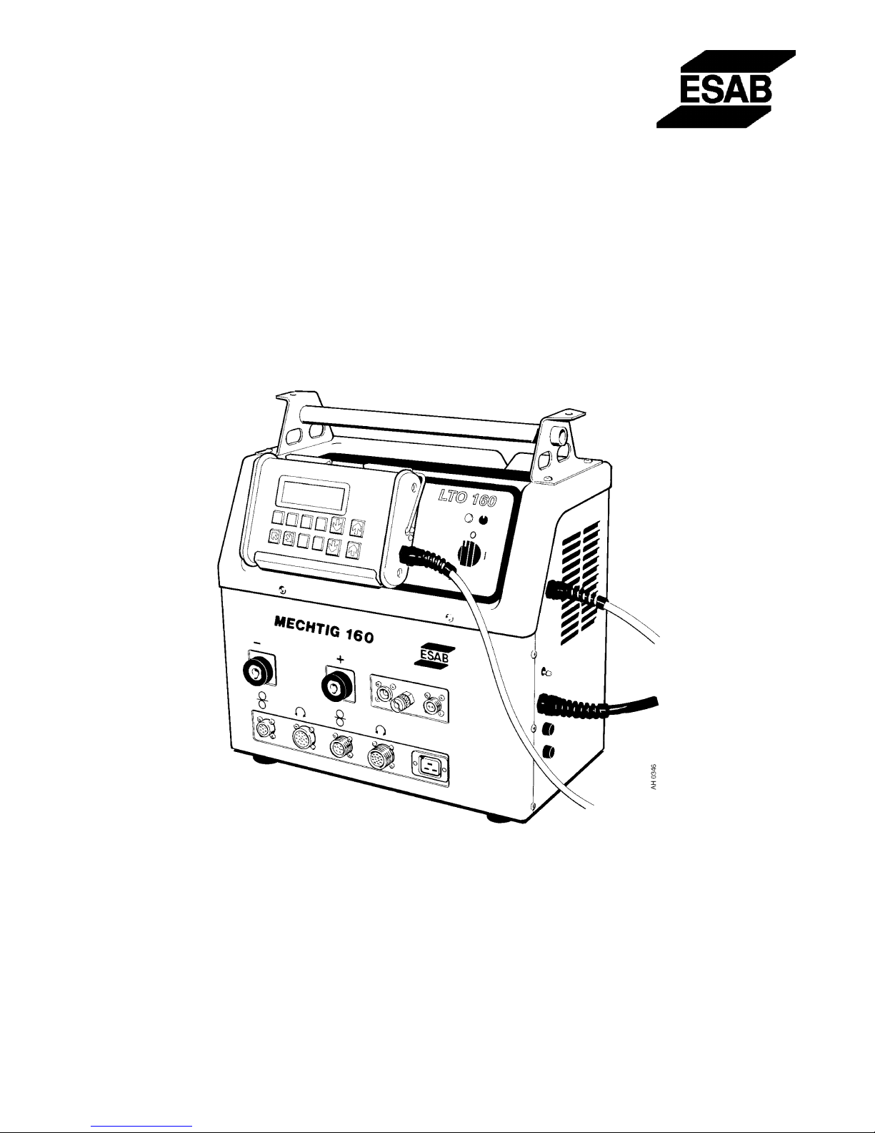
ESAB MECHTIG 160 User manual
Other ESAB Welding System manuals

ESAB
ESAB Aristo YardFeed 2000 User manual

ESAB
ESAB PT-27 User manual

ESAB
ESAB ESABMig 405 User manual

ESAB
ESAB EMP 285ic 1ph User manual

ESAB
ESAB Heliarc SR-9 Guide

ESAB
ESAB Caddy Arc 151i VRD User manual

ESAB
ESAB Aristo WeldCloud Mig U5000i User manual

ESAB
ESAB ET 200iP User manual

ESAB
ESAB LKB 265 User manual

ESAB
ESAB Aristo Mig C3000i User manual

ESAB
ESAB Aristo Origo Feed 3004 User manual

ESAB
ESAB Origo Mig 410 User manual

ESAB
ESAB A2 SF User manual

ESAB
ESAB Buddy Feed 402 User manual

ESAB
ESAB Origo Arc 406 User manual

ESAB
ESAB Origo Mig 4002c User manual

ESAB
ESAB Caddy Tig 1500i User manual

ESAB
ESAB ESABMig 325 User manual

ESAB
ESAB Mig 300i User manual

ESAB
ESAB PCM-1125 User manual


Popular Welding System manuals by other brands


TAFA
TAFA 30*8B35 owner's manual

Lincoln Electric
Lincoln Electric INVERTEC V350-PRO CE Technical specifications

CIGWELD
CIGWELD 636804 use instructions

Red-D-Arc
Red-D-Arc DC-400 Operator's manual

Hobart Welding Products
Hobart Welding Products Spool Gun DP 3035-10 owner's manual

Elettro
Elettro HI-MIG 3000 SYNERGIC instruction manual