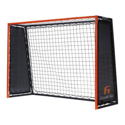
ESCALADE Goalrilla TR2001 User manual

MODEL NO.
TR2001
ALL SEASON TRAINER
2L-7246-00
THE TOUGHEST TRAINING SYSTEM ON THE PLANET.
Escalade Sport products may be manufactured and/or licensed under the following patents.
6419596, 6179733, 5919102, 5071120, 4798381, 4424968, D326128
Additional patents may be pending. One or more of the listed patents and/or pending patents may cover specific product. 2011 Escalade Sports
R
C
R
TM

MODEL NO.
TR2001
ALL SEASON TRAINER
2L-7246-00
THE TOUGHEST TRAINING SYSTEM ON THE PLANET.
1. Read this manual carefully before starting assembly. Read each step completely before beginning
each step.
2. Some smaller parts may be shipped inside larger parts. Check inside all parts and cartons before
assembling or ordering parts.
3. If hardware is tightened too soon, mounting holes may not align and parts may not easily fit together.
Leave bolts or locknuts slightly loose until you are instructed to tighten them.
4. Tools required for assembly:
Allen Wrench T1 (inlcuded) 13mm or 1/2” Open End Wrench Rubber Mallet
5. To make assembly as easy as possible, place all parts of the trainer in a cleared area and remove the
packaging material. Organize all parts as per parts identifier in the assembly manual. Do not dispose
of the packing material until assembly is completed.
6. Avoid scratching metal tube parts during the assembly process.
7. During assembly - Pivot points are to be “snug” tight only and must pivot freely.
“Fixed” connections should be tightened tight.
8. Take time to correctly orientate parts exactly as per each assembly diagram.
9. Save this instruction in the event that the manufacturer has to be contacted for replacement parts.
OWNER’S MANUAL
Please Do Not Return This Product To The Store!
Contact Escalade Sports customer service department at:
Phone: 1-888-USA-GOAL Toll-Free!
Fax: 1-866-873-3536 Toll-Free!
E-mail:[email protected]
R
Please visit our website at: www.Goalrilla.com
ON-LINE TROUBLE SHOOTING TECHNICAL ASSISTANCE
ON-LINE PARTS REQUESTS FREQUENTLY ASKED QUESTIONS
ADDITIONAL ESCALADE SPORTS PRODUCT INFORMANTION
R
Escalade Sport products may be manufactured and/or licensed under the following patents.
6419596, 6179733, 5919102, 5071120, 4798381, 4424968, D326128
Additional patents may be pending. One or more of the listed patents and/or pending patents may cover specific product. 2011 Escalade Sports
R
C
R
TM
Mailing Address:
Escalade Sports
PO Box 889
Evansville, IN 47706
FOR ASSEMBLY VIDEOS, VISIT:
www.goalrilla.com/training

WARNING
FAILURE TO FOLLOW THESE SAFETY INSTRUCTIONS MAY RESULT IN SERIOUS INJURY AND/OR
PROPERTY DAMAGE
Owner must ensure that all users know and follow these rules for safe operation of the
product.
• Product is recommended for children 9 years of age and older.
• Strangulation hazard, keep young children away from netting.
• Do not climb or jump on any part of the product including the rebound net.
• Product can tip in wind speeds above 30 mph. Do not use in gusty or severe winds.
It is recommended to store indoors during windy/stormy days.
• Never use the rebounder side and goal side at the same time.
• Balls can come back off the rebound net and frame at high speeds. Be prepared
to catch the ball.
• During play, do not wear jewelry (rings, watches, necklaces, etc.) Objects may
entangle in the net.
• When changing angle, position one hand on rebounder frame below the pivoting
bracket, this will make the adjustment process easy and safe.
• 2 persons are required to change the angle on the rebounder.
• When changing the angle on the rebounder, control the rebounder at all times
and do not release until the both spring locks are in the angle adjustment holes.
• Do not lower angle adjustment beyond the seventh hole. Trainer can become
difficult to return to other positions.
• During the adjustment process, all wheels must remain within a few inches of the
ground.
• Check product before each use for loose hardware, signs of rust and instability.
Repair before each use. Never play on damaged equipment.
• Use caution when installing the bungee straps to the net. Bungees are under high
tension and can trap fingers.
- 3 -

HARDWARE IDENTIFIER (To Scale)
H1 - M8 x 20mm
Allen Head Bolt (20 pcs)
H2 - M8 x 40mm
Allen Head Bolt (20 pcs)
H4 - M8 x 65mm
Allen Head Bolt (4 pcs)
H6 - M8
Lock Washer
(40 pcs)
H7 - M8 Locknut
(30 pcs)
H3 - M8 x 55mm
Allen Head Bolt (6 pcs)
H5 - M8 x 16mm
Flat Washer
(52 pcs)
T1 - M8 Allen
Wrench - 5mm (1 pc)
(Not to Scale)
H8 - M8 x 20mm
Plastic Step Bushing (20 pcs total)
(8 pcs are preinstalled)
(12 pcs are customer installed)
- 4 -

PARTS IDENTIFIER (Not to Scale)
P1L - Front Top
Left Corner (1 pc)
P2R - Front Top
Right Corner (1 pc)
P3 - Front Top
Cross Beam (1 pc)
P4 - Front Side
Post (2 pcs)
P5L - Top Left Side
Support Beam (1 pc)
P6R - Top Right Side
Support Beam (1 pc)
P7A - Top Back
Rebounder Beam (1 pc)
49-3/4”
42-1/4”
P7B - 3 pcs
- Bottom Back
Rebounder Beam (1 pc)
- Goal Net Support Beam (2 pcs)
P8R - Right Front
Post Leg (1 pc)
P9L - Left Front
Post Leg (1 pc)
P10R - Back Top
Right Corner (1 pc)
P11L - Back Top
Left Corner (1 pc)
- 5 -
Product ID
& Date Code
Label
49-3/4”
49-3/4”

PARTS IDENTIFIER (Not to Scale)
P12 - Left & Right Back
Rebounder Side
Beam (2 pcs)
P13L - Back Left
Bottom Corner (1 pc)
P14R - Back Right
Bottom Corner (1 pc)
P15 - Angle Adjusting
Telescoping
Assembly (2 pcs)
P16 - Ball Dampening
Net (1 pc)
P17 - Goal & Side
Net Assembly (1 pc)
P22 - Rebound Net
(2 pcs total; 1 Use - 1 for
future use)
P23 - 5” Wheel
(2 pcs)
- 6 -
49-3/4”
P18 - Fiberglass
Rod (1 set)
P19 - 74-3/4”
Ball Dampening
Net Cord (1 pc)
P20 - 86-1/2”
Side Net
Cord (2 pcs)
P24 - 6” Wheel
(2 pcs)
P21 - Bungee
Ball Loop
Connector
(24 pcs)
Warning
Label

- 7 -
IMPORTANT NOTE: Please “layout” parts exactly as per each assembly diagram. Please double check your layout to
the assembly diagram. Some parts look similar when in fact they are different. Also, please read and understand
each “IMPORTANT NOTE” added to assembly manual drawings as these notes will insure correct assembly. Also,
install all bolts in same direction as illustrated in each assembly step.
4 pcs - H1 20mm Allen Head Bolt 1 pc - P2R Front Top Right Corner
4 pcs - H2 40mm Flat Washer 1 pc - P3 Front Top Cross Beam
8 pcs - H5 Flat Washer 2 pcs - P4 Front Side Post
8 pcs - H6 Lock Washer 1 pc - T1 Allen Wrench
4 pcs - H7 Locknut 1 pc - Rubber Mallet
1 pc - P1L Front Top Left Corner 1 pc - 1/2” or 13mm End Wrench
PARTS REQUIRED:
STEP 1:
Connect all tubes as shown in FIGURE 1.
Attach tubes together using hardware as shown in FIGURE 1.
Tighten all hardware.
FIGURE 1
P4
P4
P3
P2R
P1L
H2 H2
H1
H6
H5
H1
H6
H5 H7
H6
H5
H7
H6
H5
H1
H6
H5
H7
H6
H5
H1
H6
H5
H7
H6
H5
H2
H2
IMPORTANT NOTE:
Check to make sure these
2(two) D-Rings are in this
location.
IMPORTANT NOTE:
Check to make sure these
2(two) D-Rings are in this
location.

- 8 -
1 pc - P16 Ball Dampening Net
1 pc - P19 Ball Dampening Net
Cord (74-3/4”)
STEP 2:
Place P16, “G” logo down, onto completed STEP 1 assembly. Be careful to orientate loops on both P16 and the D-Rings on P3 exactly as shown in FIGURE 2.
Next, attach P19 Cord to end D-Ring and tie a double knot as shown in FIGURE 2. Carefully weave P19 Cord through net loops and D-Rings. Pull cord tight and
finish by tying a double knot in end D-Ring as shown in FIGURE 2.
PARTS REQUIRED:
NOTE:
“G” Logo at the bottom
side of Ball Dampening Net.
P16
P3
Double
Knot
Double
Knot
FIGURE 2
P19

- 9 -
STEP 3:
Install P6R and P5L into P1L and P2R as shown in FIGURE 3.
Please double check “Goalrilla” logo is facing “outside” on both P6R and P5L. Attach using hardware as shown in FIGURE 3.
Install both P7B’s onto P5L and P6R. Attach using hardware as shown in FIGURE 3. Tighten all hardware.
IMPORTANT NOTE: INSTALL ALL BOLTS IN SAME DIRECTION AS PER ALL DIAGRAMS.
4 pcs - H1 20mm Allen Head Bolt
4 pcs - H2 40mm Allen Head Bolt
8 pcs - H5 Flat Washer
8 pcs - H6 Lock Washer
4 pcs - H7 Locknut
1 pc - P5L Top Left Side Support Beam
1 pc - P6R Top Right Side Support Beam
2 pcs - P7B Goal Net Support Beam
PARTS REQUIRED:
H1
H6
H5
H7
H6
H5
H1
H6
H5
H7
H6
H5
H2
H2
H2
H2
H1
H6 H5
H7 H6 H5
H7 H6 H5
H1
H6 H5
P6R
P5L
NOTE:
“Goalrilla”
Logo
facing
out.
NOTE:
Double check to insure
“G” logo is facing down.
P7B
P7B
P2R
P1L
FIGURE 3
1 pc - T1 Allen Wrench
1 pc - Rubber Mallet
1 pc - 1/2” or 13mm End Wrench

- 10 -
STEP 4:
Carefully slide the two underlying sleeves on the P17 Net onto each P7 Tube. Slide P17 Net assembly all the way onto each P7B Tube as shown in FIGURE 4.
Double check and orientate “G Goalrilla” exactly as shown in FIGURE 4.
1 pc - P17 Goal & Side Net Assembly
PARTS REQUIRED:
FIGURE 4
P17
P7B
P7B
NOTE:
Make sure “G Goalrilla” logo
is facing up as per diagram.
Warning
Label

- 11 -
FIGURE 5
STEP 5:
Again, be sure to orientate parts P8R and P9L exactly as shown in FIGURE 5. Install P8R and P9L into P7B’s and P4’s
as shown in FIGURE 5.
Attach P8R and P9L using hardware as shown in FIGURE 5. Tighten all hardware.
4 pcs - H1 20mm Allen Head Bolt
4 pcs - H2 40mm Allen Head Bolt
8 pcs - H5 Flat Washer
8 pcs - H6 Lock Washer
4 pcs - H7 Locknut
1 pc - P8R Right Front Post Leg
1 pc - P9L Left Front Post Leg
PARTS REQUIRED:
H7
H6
H5
H2
H1
H6
H5
H1
H6
H5
H7
H6
H5
H2
H1
H6
H5
H2
H7
H6
H5
H1
H6
H5
H7
H6
H5
H2
Rubber Mallet
NOTE:
This hole must be inside
for correct assembly.
1 pc - T1 Allen Wrench
1 pc - Rubber Mallet
1 pc - 1/2” or 13mm End Wrench
Rubber Mallet
P8R
P9L
P7B
P4
P4
Warning
Label

- 12 -
1 set - P18 Fiberglass Rod
2 pcs - P20 Side Net Cord (86-1/2” or 2.2 Meters)
PARTS REQUIRED:
STEP 6:
Snap together two pieces P18 Fiberglass Rod. Slide Rod through bottom sleeve of P17 Net and into the
bottom side hole of P9L. Carefully “Bow” the rod and install other end into bottom side hole of P8R as
shown in FIGURE 6.
1
2
P18
P18
P9L
P9L
P8R
P17
Start from
bottom -
Double
Knot
Double
Knot
Next, attach one P20 Side Net Cord with a double knot onto bottom D-Ring of P8R as shown in FIGURE 6. Fold back side net portion of P17 Net.
Next, carefully weave P20 Side Net Cord up through all loops and D-Rings as shown in FIGURE 6A. Pull P20 Cord tight and tie off using a double knot at top
end D-Ring as shown in FIGURE 6B. Repeat procedure for other side to attach side net.
Double
Knot
Double
Knot
FIGURE 6A
FIGURE 6B
P20
FIGURE 6
P17

STEP 7:
Insert P11L & P10R into P7A as shown in FIGURE 7. Attach using hardware as shown in FIGURE 7.
Insert a P12 onto each P10R and P11L as shown in FIGURE 7. Attach using hardware as shown in FIGURE 7.
IMPORTANT NOTE: PLEASE NOTE CORRECT HOLE LOCATION IN SIDE OF EACH P12 AS SHOWN IN
FIGURE 7 FOR CORRECT ASSEMBLY.
Tighten all hardware.
4 pcs - H1 20mm Allen Head Bolt
4 pcs - H2 40mm Allen Head Bolt
8 pcs - H5 Flat Washer
8 pcs - H6 Lock Washer
4 pcs - H7 Locknut
1 pc - P7A Back Top Rebounder Beam
1 pc - P10R Back Top Left Corner
1 pc - P11L Back Top Right Corner
2 pcs - P12 Left and Right Back
Rebounder Beam
1 pc - T1 Allen Wrench
1 pc - Rubber Mallet
1 pc - 1/2” or 13mm End Wrench
PARTS REQUIRED:
FIGURE 7
- 13 -
H1
H6
H5 H7
H6
H5
H2
H2
H1
H6
H5
H1
H6
H5
H1
H6
H5
H2
H7
H6
H5
H7
H6
H5
Product ID
& Date Code
Label P7A
P12
P11L
P10R
19-5/8”
IMPORTANT NOTE:
Be sure to assemble
P12 as per this diagram.
19-5/8”
P12
IMPORTANT NOTE:
Be sure to assemble
P12 as per this diagram.
STEP 8:
Insert P13L & P14R into P7B as shown in FIGURE 8. Attach using hardware as shown in FIGURE 8.
Tighten all hardware.
H1
H6
H5
H1
H6
H5
H7
H6
H5
H7
H6
H5
H2
H2 P7B
P14R
P13L
2 pcs - H1 20mm Allen Head Bolt 2 pcs - H7 Locknut 1 pc - T1 Allen Wrench
2 pcs - H2 40mm Allen Head Bolt 1 pc - P7B Back Bottom Rebounder Beam 1 pc - Rubber Mallet
4 pcs - H5 Flat Washer 1 pc - P13L Back Left Bottom Corner 1 pc - 1/2” or 13mm
4 pcs - H6 Lock Washer 1 pc - P14R Back Right Bottom Corner End Wrench
PARTS REQUIRED:
FIGURE 8

STEP 9:
Install P13L and P14R (STEP 8 assembly) into bottom of tubes P12 (STEP 7 assembly).
Attach using hardware as shown in FIGURE 9. Tighten all hardware.
2 pcs - H1 20mm Allen Head Bolt
2 pcs - H2 40mm Allen Head Bolt
4 pcs - H5 Flat Washer
4 pcs - H6 Lock Washer
2 pcs - H7 Locknut
1 pc - T1 Allen Wrench
1 pc - Rubber Hammer
1 pc - 1/2” or 13mm End Wrench
PARTS REQUIRED:
FIGURE 9
- 14 -
H1
H6
H5
H7
H6
H5
H2
H2
H7
H6
H5
H1
H6
H5
P14R
P13L
P12
P12
P7B
P7A
Product ID
& Date Code
Label

STEP 10:
With the help from at least one other adult, stand the STEP 6
assembly in vertical position as shown in FIGURE 10.
Install two pieces H8 Step Bushings into holes each side of P6R
& P5L as shown in FIGURE 10.
Turn the STEP 9 assembly to keep all nuts to inside of this frame assembly. Attach P10R to P6R and P11L to
P5L using hardware as shown in FIGURE 10. Snug, but do not tighten the H7 Locknuts as these are pivot
points.
2 pcs - H3 55mm Allen Head Bolt
4 pcs - H5 Flat Washer
2 pcs - H7 Locknut
4 pcs - H8 Plastic Step Bushing
1 set - Completed Assembly from STEP 6
1 set - Completed Assembly from STEP 9
1 pc - T1 Allen Wrench
1 pc - 1/2” or 13mm End Wrench
PARTS REQUIRED:
FIGURE 10
- 15 -
THIS STEP REQUIRES TWO OR MORE ADULTS.
IMPORTANT NOTE:
Attach this frame with
all nuts to the inside.
H3
H5
H5
H7
H8
P5L
P6R
H8
H3 H5
H5
H7
P10R
P11L
P7A
P7B
P14R
P13L
P12
P12
STEP 6
Assembly
STEP 9
Assembly

STEP 11:
With the help from at least one other adult, install two pieces H8 Step
Bushings into both P12’s, P8R and P9L as shown in FIGURE 11.
Install P15, both sides using hardware as shown in FIGURE 11.
Snug this hardware but do not tighten as each end of P15 is a pivot point.
4 pcs - H3 55mm Allen Head Bolt
8 pcs - H5 Flat Washer
4 pcs - H7 Locknut
8 pcs - H8 Plastic Step Bushing
2 pcs - P15 Angle Adjusting
Telescoping Assembly
1 pc - T1 Allen Wrench
1 pc - 1/2” or 13mm End Wrench
PARTS REQUIRED:
FIGURE 11
- 16 -
THIS STEP REQUIRES TWO OR MORE ADULTS.
H8
H8
H5 H3
H5
H7
H8
H5 H3
H5
H3
H8
H8
H8
H5
H7
H5
H3
H8
H8
H5
H3
H5 H7
P15
P15
P12
P12
P8R
P9L

STEP 12:
With the help from at least one other adult, attach P23 5” Wheels on P8R
& P9L and attach P24 6” Wheels on P13L and P14R using hardware as
shown in FIGURE 12.
Snug, but do not tighten these wheels as they must be able to spin
freely.
4 pcs - H4 65mm Allen Head Bolt
4 pcs - H7 Locknut
2 pcs - P23 5” Wheel
2 pcs - P24 6” Wheel
1 pc - T1 Allen Wrench
1 pc - 1/2” or 13mm End Wrench
PARTS REQUIRED:
FIGURE 12
- 17 -
THIS STEP REQUIRES TWO OR MORE ADULTS.
P24
(6” Wheel)
P24
(6” Wheel)
P23
(5” Wheel)
P23
(5” Wheel)
H4
H4
H7
H7
H7
H7
H4
P13L
P14R
P8R
P9L
H4

FIGURE 13
- 18 -
STEP 13:
IMPORTANT NOTE: Both the net frame and rebound net are both square.
Please follow the P21 Loop Connector sequance below for ease of rebound
net installation (A, B, Cand D).
When complete, there will be (6) loop connectors per each side.
An additional adult who can squeeze the net close to the frame during the P21
Loop Connector assembly will greatly ease this net installation.
Please locate each “Ball” of the loop connector in “back” of the frame when loop connector is hooked together.
24 pcs - P21 Bungee Ball Loop
Connector
1 pc - P22 Rebound Net
PARTS REQUIRED:
A
A
A
A
B
D
D
D
D
C
C
C
C
NOTE:
Attach four corners
first for ease of
insta
llation.
B
B
B
NOTE:
There will be (6) loop connectors
per each side.

CARE AND MAINTENANCE
• Before each use, check bungee cord, netting and fabric for tears and
fraying. Replace if necessary.
• Before each use, check nuts and bolts for proper tightness.
• The frame is powder coated, If rust should appear, remove loose paint,
sand lightly and paint with exterior flat matte finish enamel paint.
• Keep covered or take inside during windy/stormy days.
• Keep the dampening net down to extend the life of the fabric.
INSTRUCTIONS
To move the product, flip the dampening net up and over the back of the goal net to avoid
tripping. Grab the top middle of the product (orange cross bar) and carefully tip toward your
body until the wheels engage the ground. Move to desired location and tip product back
into position.
To change the angle of the rebounder, 2 persons are required. Position one person on each
side of the rebounder. In unison, firmly grasp frame (beneath the pivoting bracket) and pull
spring locks upwards so that they disengage from their locking holes. While continuing to
grasp the frame, slowly raise or lower the rebounder while keeping the wheels in contact /
a few inches from the ground until the desired angle is reached. Release the spring locks
and continue to adjust the angle until a click is heard from both spring locks, this will signify
that the trainer is now locked in position.
- 19 -

PRODUCT PARTS LIST
PARTS# KEY# DESCRIPTION QTY.
H1 M8 x 20mm Allen Head Bolt 20
H2 M8 x 40mm Allen Head Bolt 20
H3 M8 x 55mm Allen Head Bolt 6
H4 M8 x 65mm Allen Head Bolt 4
H5 M8 x 16mm Flat Washer 52
H6 M8 Lock Washer 40
H7 M8 Locknut 30
H8 M8 x 20mm Plastic Step Bushing (20pcs)
- Preinstalled 8
- Customer Installed 12
T1 M8 Allen Wrench (5mm) 1
P1L Front Top Left Corner 1
P2R Front Top Right Corner 1
P3 Front Top Cross Beam 1
P4 Front Side Post 2
P5L Top Left Side Support Beam 1
P6R Top Right Side Support Beam 1
P7A Top Back Rebounder Beam 1
P7B Bottom Back Rebounder Beam 1
Goal Net Support Beam 2
P8R Right Front Post Leg 1
P9L Left Front Post Leg 1
P10R Back Top Right Corner 1
P11L Back Top Left Corner 1
P12 Left & Right Back Rebounder Side Beam 2
P13L Back Left Bottom Corner 1
P14R Back Right Bottom Corner 1
P15 Angle Adjusting Telescoping Assembly 2
P16 Ball Dampening Net 1
P17 Goal & Side Net Assembly 1
P18 Fiberglass Rod (set) 1
P19 74-3/4” Ball Dampening Net Cord 1
P20 86-1/2” Side Net Cord 2
P21 Bungee Ball Loop Connector 24
P22 Rebound Net (1 Use - 1 for future use) 2
P23 5” Wheel 2
P24 6” Wheel 2
C1 Front Feet (included Screws) 2
K1 Hardware Kit 1
M1 Owner’s Manual 1
TR2001W / F
- 20 -
TR2001-H1
TR2001-H2
TR2001-H3
TR2001-H4
TR2001-H5
TR2001-H6
TR2001-H7
TR2001-H8
TR2001-T1
TR2001-P1L
TR2001-P2R
TR2001-P3
TR2001-P4
TR2001-P5L
TR2001-P6R
TR2001-P7A
TR2001-P7B
TR2001-P8R
TR2001-P9L
TR2001-P10R
TR2001-P11L
TR2001-P12
TR2001-P13L
TR2001-P14R
TR2001-P15
TR2001-P16
TR2001-P17
TR2001-P18
TR2001-P19
TR2001-P20
TR2001-P21
TR2000-P22
TR2000-P23
TR2000-P24
TR2001-C1
TR2001-K1
TR2001-M1
To purchase these parts, please contact Escalade Sports Customer Service
Table of contents
Other ESCALADE Fitness Equipment manuals