eschmann RX500 User manual
RX500
OPERATION TABLE
698265 T-SM13h
ServiceManual

ServiceManual
Eschmann After Sales Service Department
TheEschmannAfterSalesServiceDepartmentisstaffedandequippedtoprovideadviceand assistance
during normal office hours.To avoid delays when making enquires, please quote the Model and Serial
Number of your Operation Table which is shown on the Serial Number plate, the location of which is
shown below.Please ensure you include all alpha and numeric digits of the Serial Number.
For further information visit www.eschmann.co.uk
All correspondence relating to the after sales service of Eschmann Equipment to be addressed to :
UK Customers
Eschmann Equipment, Peter Road, Lancing,West Sussex BN15 8TJ, England.
Tel: +44 (0) 1903 765040. Fax: +44 (0) 1903 762006.
Overseas Customers
Contact your local distributor. In case of doubt contact Eschmann Equipment.
Patents and Trade marks
The ESCHMANN name and logo are registered trade marks of Eschmann Holdings Limited.
“Eschmann Equipment”is a trading name of Eschmann Holdings Limited.
“RX600” is a trade mark of Eschmann Holdings Limited.
Patents: GB 2260075 & GB 2242624;France 536922 & 450836;US5116032;
Germany P69206378.1 & P69104883.5;Italy 536922 & 450836.
Patents pending in Japan, application numbers 263630/92 & 97990/91.
Copyright © 2002
Allrights reserved.This booklet is protectedbycopyright.No partofitmay be reproduced, storedinaretrieval
systemortransmittedinanyformorbyany means,electronic,mechanical,photocopying,recordingorotherwise
without written permission from Eschmann HoldingsLimited.
Theinformationinthispublicationwascorrectatthetimeofgoingtoprint.TheCompany,however,reservesthe
right to modify or improve the equipment referred to.
If the CE mark is affixed to the product, it indicates compliance with Council Directive
93/42/EEC of 14 June 1993 concerning medical devices.
T-SM13h October 2002
TheSerialNumberPlate
is on the inside of the
long trunk section here.
Preliminary Information
Technical Data
Safety Notes
Introduction
Description
Maintenance

T-SM13h 3/40
RX500RX500
RX500RX500
RX500
OPERATION TABLE
READ THESE INSTRUCTIONS BEFORE USE
Keep these Instructionsina safeconvenientplacefor future reference.Read in conjunction
with the relevant Publications detailed in the preliminary information section.
CONTENTS
Section Contents Page
1. PRELIMINARY INFORMATION ..................... 4
2. TECHNICAL DATA.......................................... 4
3. SAFETY NOTES ............................................ 5
4. INTRODUCTION ............................................ 6
General ....................................................... 7
Electrical System ........................................ 7
Main Control Board ................................. 7
Height Opto Board .................................. 7
Tilt Opto Board........................................ 7
Base Distribution Board ..........................8
Top-Of-Column Distribution Board .......... 8
Top-Of-Column Solenoids Board ............ 8
Power Circuits ......................................... 8
Hand Control ........................................... 8
Footswitch ............................................... 8
Table-Base ON/OFF Control ................... 8
Built-in Battery Charger........................... 9
External Battery Charger ........................ 9
Standby System Connections................. 9
5. DESCRIPTION ............................................. 10
6. MAINTENANCE ........................................... 14
General ..................................................... 14
Cleaning and Storage ............................... 14
General Care and Lubrication................... 14
Gas Springs .......................................... 14
Head, Leg, & Infill Sections................... 14
Head, Leg, & Infill-Locking Mech. ......... 14
Long and Short Trunk Sections............. 14
Radiographic Tops................................. 14
Underside of the Table Base ................. 14
Access to Fuses.................................... 15
Hand control.......................................... 15
After Maintenance................................. 15
Functional Checks .................................... 15
General ................................................. 15
Hydraulic System...................................... 18
General ................................................. 18
Topping-Up Reservoir ........................... 18
Adjustments .............................................. 18
Trendelenburg Microswitch ................... 18
Lateral Tilt Opto..................................... 18
Break Microswitch ................................. 19
Tilt Switch.............................................. 20
Removal and Installation........................... 20
General ................................................. 20
Remove Table Base Covers .................. 20
Install Table End Base Covers .............. 20
Remove Top-Of-Column Covers ........... 21
Install Top-Of-Column Covers ............... 21
Releasing Telescopic Cover & Upstand 21
Refixing Telescopic Cover & Upstand ... 21
Removing the Telescopic Cover............ 21
Replacing the Telescopic Cover ............ 21
Section Contents Page
Remove Long & ShortTrunk Assemblies . 23
Install Long & Short Trunk Assemblies . 23
Remove Break Cylinder ........................ 26
Install Break Cylinder ............................ 26
Remove Lateral Tilt Cylinder ................. 27
Install Lateral Tilt Cylinder.. ................... 27
Remove Trendelenburg Cylinder........... 27
Install Trendelenburg Cylinder............... 28
Remove Height Cylinder ....................... 28
Install Height Cylinder ........................... 28
Gas Spring Replacement...................... 29
Remove Batteries.................................. 29
Install Batteries ..................................... 29
Remove the Base Feet ......................... 29
Install the Base Feet ............................. 30
Infillinterlockingmechanismreplacement ..............
30
Pushbuttonreplacementandadjustment ..............
30
Remove/Install Hydraulic Components .. 30
Remove/Install Electrical Components... 30
Fault Diagnosis ......................................... 31
Table 1: Fault Diagnosis ........................ 31
Circuit Diagram Index............................ 30
Table 2: Codes for 2-Digit Display ......... 34
FIGURES
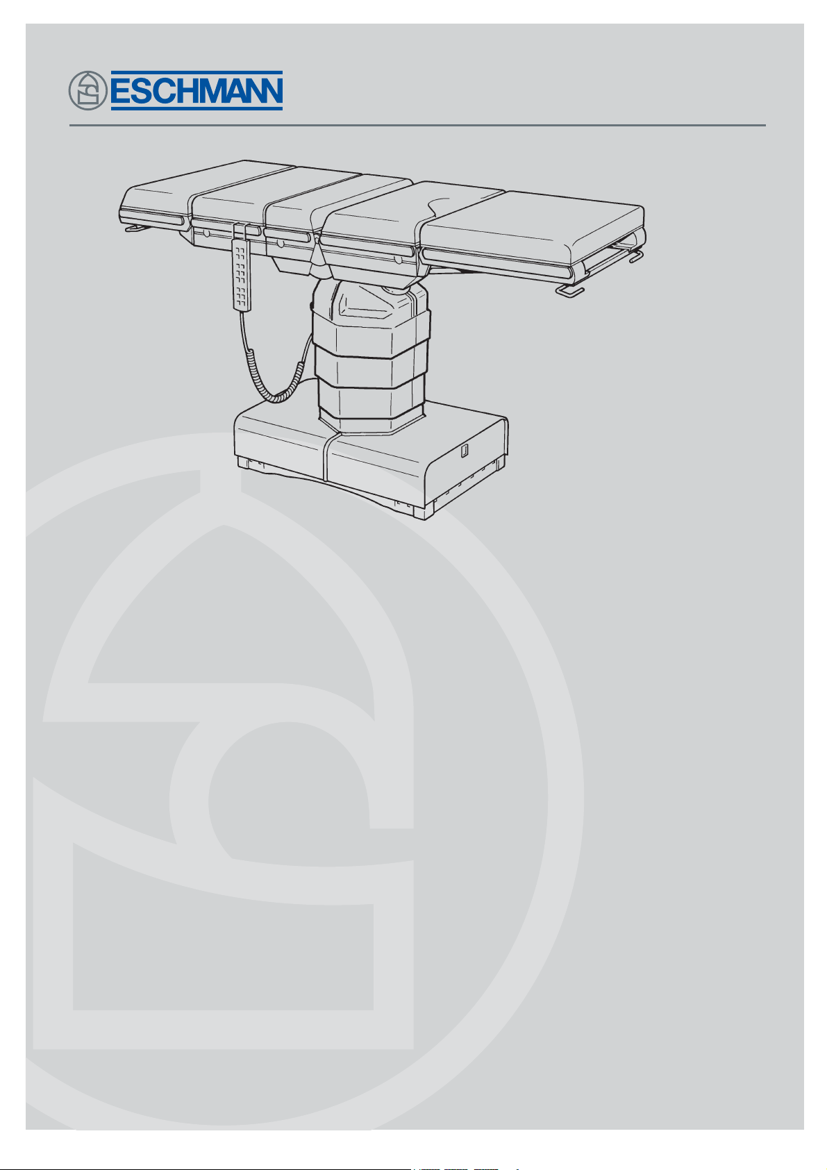
1 RX500 Operation Table .................................. 6
2 RX500 Operation Table: Base Details .......... 10
3 RX500 Operation Table: Column/Trunk Detail 12
4 RX500OperationTable:Base
(shorttrunkend) ....
13
5 RX500OperationTable:Base
(longtrunkend) .....
13
6 Table Tilted for Access.................................. 15
7 Base Detail Table Tilted ................................ 15
8 Main Control Board....................................... 15
9 Hydraulic System - Schematic Diagram....... 16
10 Hydraulic System - Main Components ......... 17
11 Trendelenburg Microswitch ........................... 19
12 Lateral Tilt Opto ............................................ 19
13 Break Microswitch ........................................ 19
14 Tilt Switch ..................................................... 20
15 Cover Retaining Push Rivets........................ 21
16 Top of Column Hinge Assembly Detail ......... 22
17 Top of Trendelenburg Cylinder...................... 23
18 Break Cylinders ............................................ 24
19 Lateral Tilt Cylinder....................................... 25
20 Trendelenburg Cylinder ................................ 27
21 Top of Column Detail ....................................28
22 Bottom of Height Cylinder Detail .................. 28
23 Gas Spring Detail .........................................29
24 Base Feet Detail ........................................... 29
25 Infill interlocking mechanism......................... 30
26 Catch mechanism......................................... 30
27 Hand Control Functions................................ 34
28-35Circuit Diagrams*.................................35-40
(* also see Circuit Diagram Index on page 33)

4/40 T-SM13h
1. PRELIMINARY INFORMATION
DIMENSION
Table with standard table-top (Fig. 1) :
Width including sidebars .............................560mm
Sidebars ......................................(31.75 x 6.35)mm
Overall length (with infill section)...............2000mm
Minimum table height (without mattresses) ....... 700mm
Maximum table height (without mattresses) ....1040mm
SAFETY
The table is built to comply with BS5724 Part 1,
BS5724 Part 2 Section 2.22, IEC601-1,
IEC601-1-2:1993andBS6859 Part1.The mattresses
comply with BS2891.
TABLE LOADING
The standard table (Fig.1) satisfies a static load test
in accordance with the requirements of BS5724
MOVEMENTS
Maximum Trendelenburg....................................35°
Maximum Reverse Trendelenburg......................35°
Maximum Lateral Tilt (left and right)...................15°
Maximum Extension.........................................220°
Maximum Flexion .............................................130°
Head section adjustment ................................ ±45°
Leg section adjustment ......................... (-100+10)°
Note: With the table at minimum height, maximum
Trendelenburg, and maximum head and leg section
movements are reduced due to physical restrictions
(i.e. proximity of floor)..
WEIGHT (nominal)
Table with standard table-top (Fig. 1) ............ 300kg
SYMBOLS & SAFETY CLASSIFICATIONS
Caution Refer to the accompanying
documents, the “Instructions for Use”.
or IPX 4 indicates that the equipment will
withstand a moderate quantity of fluid spilled
from above.
Safety Category
Indicates that the equipment is in safety
category BF, i.e. it is manufactured to a
safety standard which agrees with
international regulations for medical electrical
equipment, and provides a high degree of protection
againstelectricshock.The symbolalsoindicates that
the equipment will not be damaged by defibrillator
discharge.
Indicates that the equipment is in safety
category B, i.e. it is manufactured to a safety
standard which agrees with international regulations
for medical electrical equipment, and provides a
minimumdegreeof protectionagainst electricshock.
Class 2 Indicates that the built-in battery
charger is designed to electrical protection Class 2.
Anaesthetic Proof
Indicatesthatthepartsoftheequipmentmarked
AP are designed for use within a distance of (5
to 25cm) of a part of an enclosed medical gas
system. BS5724 Part 1, 1989 refers.
Indicates that the parts of the equipment
marked APG are designed for use within a
distanceof5cmofapartofanenclosedmedical
gas system. BS5724 Part 1,1989 refers.
WARNING
The head section of this operation table is
classified as‘EQUIPMENT not suitable for use in
the presence of a flammable anaesthetic mixture
with air or with Oxygen or Nitrous Oxide’ and is
NOT classified as ‘Category AP Equipment’ or
‘Category APG Equipment’ when it (the head
section) is in its lowest position and the table top
is in full Trendelenburg position.
Inspection
The table must be inspected at regular intervals, and
if necessary, serviced, to ensure that it complies with
all AP and APG requirements relevant to physical
deterioration or breakage of electrical components,
connections and cable insulation.
1.1 This Service Manual should be referred to for details of the RX500 Powered Operation Table,
REF 80-600-29 (series) and REF 80-600-61 (series) having Serial Number R5BC8J0000 or above.
RelatedTechnical Publications, available on request from Eschmann Equipment :-
Instructions for Use - T-IM28 - RX500 Powered Operation Table
Illustrated Parts List - T-IPL11- RX500 Powered Operation Table
1.2 Instruction andService Manualsshould bereadilyaccessible for referencepriorto andwhen operating,
cleaning and servicing the Operation Table.
2.TECHNICAL DATA

T-SM13h 5/40
RX500RX500
RX500RX500
RX500
OPERATION TABLE
2.TECHNICAL DATA
Antistatic requirements
The table has an antistatic pathway from the table-
top, through an internal resistor to the castors, which
are held in contact with the floor at all times.
CAUTION
1. To complete the antistatic pathway,the table
must be used on an electrically conductive, or
on an antistatic floor.
2. Always use purpose-designed Eschmann
mattresses to maintain the antistatic pathway.
Electrical data
System Power
Batteries:
Type....................................... Two sealed lead-acid
Output (each) ......................................... 12V 24Ah
Built-In Battery Charger:
Input ...................................... 200-240Vac 50/60Hz
Output ..............................27.6Vdc (nom) 3A (max)
System Fuses:
Motor.......................................30A 1.5in. (AGU 30)
Base Control Board: (1)........F6.3A 250V 20mm
(1)........T2.5A 250V 20mm
(1)...........T2A 250V 20mm
CAUTION
This equipment contains environmentally
hazardous lead-acid batteries. If the batteries fail,
or if the equipment is to be disposed of, it is
recommended that the batteries are taken to a
disposal site designated for the disposal of lead-
acid batteries, or that the batteries are collected
by an agent who specialises in the collection of
lead-acid batteries.
Hydraulic Oil
Type.....................Eschmann RX (Part No. 699408)
3. SAFETY NOTES
Attention to the following points will prolong the life and efficiency of the RX500 Powered
OperationTable and will help to avoid the risk of accidents, or damage.
DO:
♦Keep the Instruction Manual close-to-hand.
♦Readtheinstructionscarefullybefore usingtable.
♦Checkthat theheadandleg sectionsaresecure,
and put the table base in the braked position
before use.
♦Disconnect the built-in battery charger from the
powersupplyandswitchtableoffbeforewashing.
♦Readandfollowtheinstructionsforcleaning,and
for the care of the mattresses.
♦Use the correct mattresses and accessories.
♦Remove table accessories and their clamps (in
particular rotary clamps) from sidebars, when
they are not being used.
♦Ensurethatthetableisservicedatregularintervals
(every 6 months is the recommended frequency)
byEschmannpersonnelonly,oraccreditedagents.
DO NOT:
♦Lift the table by its table-top.
♦Pushthe tableoverroughsurfaces,usea trolley.
♦Drop the table (or individual sections).
♦Put heavy weights on the table sections.
♦Put sharp objects on, or against, mattresses,
pads, or the radiographic table-tops.
♦Dropheavyobjectsontotheradiographictable-tops.
♦Spill oil, ether, or other fluids onto the
mattresses or the pads.
♦Pull the table by any of the table-top sections,
always push it.
♦Hold or support the leg section by its black
radiographictop,as thisis aremovable itemand
might come off.
Note: The table cannot be used (under normal
circumstances) with table base standby door open.
MISCELLANEOUS
WARNING
The RX500 Powered Operation Table has been designed to minimise the possibility of accidental
electrosurgery burns. Contact with any metal surfaces (e.g. table side bars, or other equipment
etc.) can cause burns during electrosurgery and must be avoided.
With the table in (or during transition into) the castor position, the centre of gravity of the patient
(normally the perineum) should lie no more than 200mm away from the centre of the column (i.e. no
more than the length of the short trunk section). Whenever this is not practical the overhanging
weight of the patient and table should be adequately supported (e.g. by at least two able people).
Also see Warnings in Instruction for Use and within the text of this publication.

6/40 T-SM13h
1. Head section
2. Infill section
3. Short trunk section
4. Long trunk section
5 Leg section
6. Release bar
7. Gas springs
8. Release button (leg section removal)
9. Release button (Infill section removal)
10. Hand control
11. Release button (head section removal)
12. Release bar
13. Telescopic column
14. Table base
15. Hand control or footswitch socket
16. Hand control or footswitch socket
View on base short trunk end
17. Hand control plug
18. Table (on/off) switch
19. Push button switches to engage standby
hydraulic connectors
20. Standby hydraulic connectors
21. Quick-charge external battery charge socket
22. High current 30A fuse
23. Standby door microswitch
24. Standby power pack connector
25. Standby door
26. Built-in battery charger socket
27. Battery charger ‘on’ indicator (green)
28. Battery charger door
29. Removable mains lead
30. Cover retaining screws
31. Top of column covers
View on base long trunk end
Fig. 1 RX500 Powered OperationTable
4. INTRODUCTION
View on ‘A’

T-SM13h 7/40
RX500RX500
RX500RX500
RX500
OPERATION TABLE
4. INTRODUCTION
GENERAL
4.1 This Service Manual contains a technical
description and maintenance procedures for the
RX500 Powered OperationTable.
4.2 The RX500 PoweredOperationTableisa fully
mobile table with a five section top comprising short
and long trunk sections, an interchangeable infill
section and head and leg sections.
4.3 The table enables a full range of surgical and
radiographicprocedurestobedoneincluding:general,
urological,gynaecological,cardiothoracic,ophthalmic,
ENT and neurosurgical. Certain procedures require
theaddition of specificaccessories, informationabout
which is available on request.
4.4 The RX500 Powered Operation Table is an
electro-hydraulically operated, battery powered unit,
remotely operated from a touch-button hand control, or
a footswitch, both plug into the top of the table column
4.5 Power is provided by two 12V sealed lead-acid
batteries in the table base. The 12V batteries are
connected in series to give an output voltage of 24V.
Tricklechargingforthebatteriesisprovidedbyaninbuilt
battery charger, provision is also made for connection
ofanexternalbatterychargerforquickbatterycharging.
4.6 All table top trunk movements are electrically
controlled using either the hand control or, as an
optionalaccessory thefour functionfootswitch(height
andTrendelenburgonly)which isusedbythesurgeon
during certain procedures.
4.7 The operation table has these main sections:
GBase.
GCentral column.
GLong trunk.
GShort trunk.
GInterchangeablehead,legand infillsections.
NOTE: Instruction and Service manuals should be
readily accessible for reference prior to, and when
operating, cleaning, and servicing the table.
ELECTRICAL SYSTEM
NOTE: Electrical/electronic circuit diagrams are
provided at the end of this Manual in section 6 (see
index page 33).
Main Control Board
4.8 The main control board receives signals from
the hand control via an RS485 serial communication
link. The board also receives signals from the
footswitch, base cover switches, levelling
microswitches, tilt switch, opto boards, standby unit
socket, door switch and table on/off controls.
4.9 Outputs from the main control board pass
to the hand control via an RS485 serial
communicationlink, to thehydraulicsolenoids viathe
top-of-column distribution and solenoid boards, and
to the base distribution board, motor on/off control
and motor direction control.The main control board
is supplied with 24V d.c. from the batteries and
generates its own 12V d.c.and 5V d.c. supplies.
4.10 The principal functional areas of the main
control board are:
- Input buffering (pull-up and pull-down resistors
and capacitors).
- The microcontroller, which uses software to
implement table control functions.
- Outputbuffering(current driversandlevelshifters).
- Motor direction drive and on/off control.
Height Opto Board
4.11 The height opto board is fitted at the base of
thecolumnin afixedpositionrelativetothebaseplate.
It responds to a metal reflector plate which moves up
and down with the column chassis and hence with
the table top.When the reflector moves in front of the
three reflective opto sensors (only two are used)
electrical signals are generated to signal to the main
control board that the table is at or above ‘minimum
height’, or in the ‘castor’ position.
4.12 Whenthe reflectorplateis infront of reflective
opto coupler 01 and at the correct distance from it, a
signal is produced which passes via J1 on the opto
boardand the10-wayribboncabletoJ22 onthemain
control board.
4.13 When the reflector plate is in front of both
reflective opto couplers 01 and 03 signals from both
pass to the main control board which stops the table
movement at the correct position.
Tilt Opto Board
4.14 The tilt opto board is fitted at the top of the
columninafixedpositionrelativetotheyoke.Itresponds
to a metal plate which moves with the yoke and hence
with the table top.When the reflector moves in front of
the opto sensors electrical signals are generated to
signal the main control board that the table is level.
4.15 When the reflector plate moves in front of the
optosensor,alogicsignal 0is producedwhichpasses
via J1 on the opto board to the top of column
distributionboard andthen via a 10-wayribboncable
to J2-4 on the main control board.
4.16 When the reflector plate is not in front of the
opto sensor, a logic signal 1 is produced which is
passed to the main control board as above.

8/40 T-SM13h
Base Distribution Board
4.17 This board receives signals from the main
control board for the height (extend) solenoid, the
height(contract)solenoid, thepump-isolate(forward)
solenoid and the pump-isolate (reverse) solenoid.
4.18 The board also passes signals to the main
control board from the cover microswitches .
4.19 Any inductive overswings from the solenoids
are blocked by diodes Dl to D4. PL7 on the base
distribution board is connected via a 14-way ribbon
cable to J4 on the main control board.
Top-of-Column Distribution Board
4.20 Thisboard connectsto J2onthe maincontrol
board via a 34-way retractable ribbon cable which
terminates on PL1 of this board.It distributes signals
to 10-way hand control/footswitch sockets PL2 and
PL3, and to:
Gthe tilt switch via PL7
Gthe Trendelenburg level position microswitch
via PL5
Gthe lateral tilt opto board via PL4
Gthe break level position microswitch via PL6
Gtop-of-column solenoids board via PL8
Gtable ON/OFF switch via PL9
Top-of-Column Solenoids Board
4.21 This board receives signals on J7 via a 10-
way ribbon cable from J8 on the top-of-column
distributionboardtodrivethe top-of-columnsolenoids
via cage clamp connectors J1 to J6. It also blocks
inductiveoverswings fromsolenoidsusing diodesD1
to D6.
Power Circuits
4.22 The power source for the table are two 12V,
24Ah sealed lead acid batteries connected in series.
A30A in-line,high currentfuse protectsthebatteries,
motor, FET’s, relay and interconnections.The fuse is
fitted on a panel in the table base.
4.23 Current from the batteries passes via the
reversingrelay,where itisswitchedbytheFET’s,and
then passes to the pump motor and returns to the
batteries. The 24V d.c. supply is also routed to the
hydraulic solenoids and the main control board.
Hand control
4.24 The RX500 hand control communicates with
the main control board via an RS485 serial
communication link. The hand control contains a
microcontroller which receives inputs from the hand
control buttons and generates outputs which go to
the hand control LED’s and the hand control audible
warning device.The microcontroller uses software to
implement hand control, control functions.
4.25 Thehand-controlincorporatesa2-digitdisplay
that indicates a code if a problem should occur.Such
problems could be the result of the user pushing a
button in the wrong sequence or at the wrong time or
of a system failure (see Table 1 - Fault Diagnosis,
Table 2 - Codes for 2-Digit display and Fig. 27)
Footswitch (Optional Accessory)
4.26 The footswitch plugs into either of the two 10-
way sockets used by the hand control. It uses the
same +5V d.c. and 0V pins, but the signal lines are
differentfrom thoseof thehandcontrol.Thefootswitch
does not use a serial communication link.
4.27 There are four functions on the footswitch:
GHeight up
GHeight down
GTrendelenburg
GReverse Trendelenburg.
4.28 Eachofthese fourfunctionsisassociated with
two microswitches mounted inside the body of the
footswitch, one normallyopenand theother normally
closed. The normally open microswitch for each
function is connected on one side to the +5V d.c. line
and on the other side to a common ‘alarm’ line.The
normally closed microswitch for each function is
connectedon oneside tothe0V lineand ontheother
side to an individual input line on the main control
board.If,foranyfunction ofthefootswitch, e.g.height
up, the normally open microswitch operates and the
normally closed microswitch does not, or vice versa,
themaincontrolboardwill recogniseafaultandfreeze
the table.The likelihood of two microswitches failing
at the same time is very remote.
Table Base ON/OFF Control
4.29 An ‘on/off’ toggle switch, fitted on the top of
the table column, switches 24V d.c. on the main
control board.To isolate the system the 30Amp fuse
should be removed.
4. INTRODUCTION

T-SM13h 9/40
RX500RX500
RX500RX500
RX500
OPERATION TABLE
Built-in Battery Charger
4.30 This is a low current output ‘trickle’ charger
which replenishes an average day’s table use of the
batteries with an overnight charge.
4.31 The mains input comes via the mains lead,
which should be fitted with a fused plug.The output
of the charger is regulated to provide 27.6V d.c. to
the batteries for float charging. This voltage will fall
when the batteries are not completely charged and
hence are drawing a significant current.The charger
has short-circuit and thermal protection.There is an
output from the board which supplies current to the
batteries, an output to the ‘trickle’ charger indicator
LED and an input from the external charger.Current
from either the internal or the external charger is
routed to the batteries via the‘trickle’charger board.
External Battery Charger (Optional Accessory)
4.32 The external battery charger plugs into the
external battery charger socket in the table base and
supplies current via the ‘trickle’ charger board to the
batteries.
4. INTRODUCTION
Standby System Connections
4.33 An RX Standby Unit (optional accessory)
which provides standby hydraulic and electrical
services, can be connected to the RX500 table via
hydraulic connectors and an electrical socket behind
the door on the table base (short trunk section end).
4.34 Nexttothehydraulicconnectorsare twopush-
buttonswhich releasestoredhydraulicpressurewhen
the standby hydraulic connections are made.This is
done by energizing the pump forward and reverse
solenoids with power from the standby unit.
4.35 To connect the standby unit to the table it is
necessary to open the base door. This operates a
microswitchwhichdisconnectsthe maincontrolboard
solenoid control circuits from the solenoids so that
they can be controlled by the standby unit, also the
pumpmotorishydraulicallyisolatedfrom thehydraulic
solenoids. The electrical signals from the standby
socket pass to J1 on the main control board (15-way
D-connector).
10/40 T-SM13h
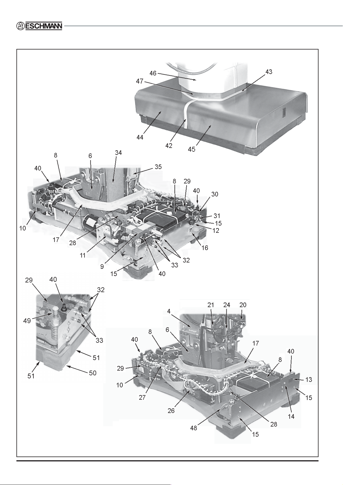
Fig. 2 RX500 OperationTable : Base details, covers on and off
5. DESCRIPTION
For greater detail of
the table base ends also
refer to Fig. 4 and 5

T-SM13h 11/40
RX500RX500
RX500RX500
RX500
OPERATION TABLE
5. DESCRIPTION
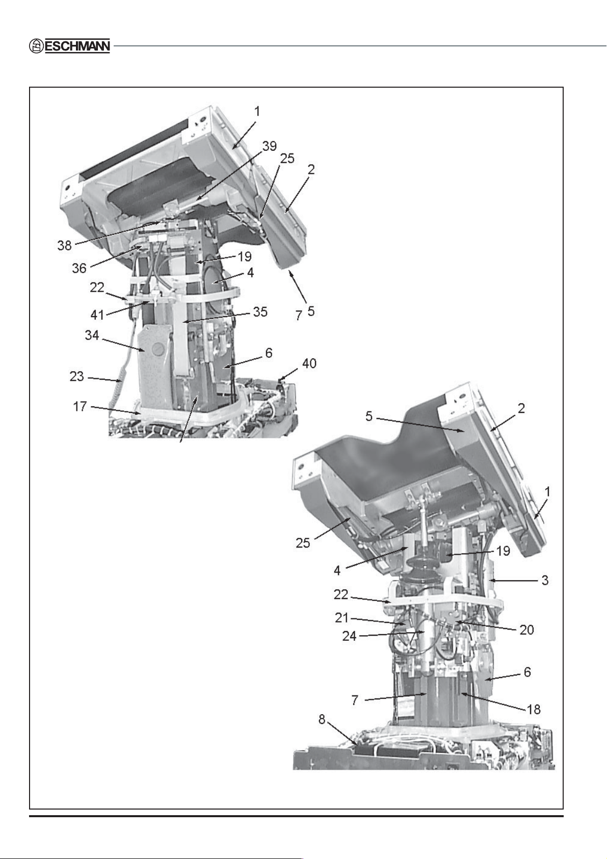
Key to Figs 2 and 3
1. Short trunk assembly
2. Long trunk assembly
3. Lateral tilt cylinder
4. Wrap around
5. Trunk assembly plastic covers
6. Wedge
7. Outer column
8. Battery
9. Manifold block No 1
10. Castor plate guide pillar
11. Hydraulic power unit
12. High current fuse, 30A
13. Mains socket
14. Battery charging LED (green)
15. Cover retaining screw location
16. External battery charger socket
17. Drip gutter
18. Opto reflector plate
19. Inner column
20. Manifold block No 4
21. Manifold block No 3
22. Upper bezel
23. Cable from hand control
24. Trendelenburg cylinder
25. Break cylinders
26. Main control PCB
27. Base distribution PCB
28. Castor frame assembly
29. Manifold block No 2
30. Door microswitch
31. Standby power pack connector
32. Standby hydraulic connectors
33. Push buttons to engage standby
hydraulic connectors
34. Hydraulic reservoir
35. Ribbon cable reel assembly
36. Top-of-column distribution PCB
37. Hinge
38. Lateral tilt opto board
39. Yoke
40. Cover microswitch
41. Table ‘on/off’ switch
42 Base seal
43. Column seal
44. Long trunk base cover
45. Short trunk base cover
46. Telescopic column cover
47. Column upstand
48. Antistatic discharge path resistor
49. Base cover spring support
50. Base foot
51. Base skirt
12/40 T-SM13h
5. DESCRIPTION
Fig. 3 RX500 OperationTable : Column and trunk section detail
T-SM13h 13/40
RX500RX500
RX500RX500
RX500
OPERATION TABLE
5. DESCRIPTION
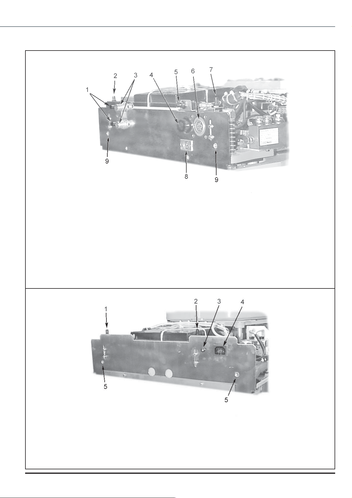
Fig. 5 RX500 Operation Table Base Detail (Long trunk end)
1 Standby hydraulic push buttons
2 Base cover microswitch
3 Standby hydraulic connectors
4 High current (30A) fuse
5 Door Microswitch
6 Standby power pack connector
7 Base cover microswitch
8 External battery charger socket
9 Fixing for cover retaining screw
Fig. 4 RX500 OperationTable Base Detail (Short trunk end)
1 Base cover microswitch
2 Base cover microswitch
3 Mains charging LED
4 Mains connection socket
5 Fixing for cover retaining screw

14/40 T-SM13h
GENERAL
6.1 Maintenance of the RX500 Powered
Operation Table falls into the following categories:
GCleaning and storage.
GAdjustments.
GGeneral care and lubrication.
GRemoval and Installation.
GFunctional checks.
GFault diagnosis.
GHydraulic system.
CLEANING AND STORAGE
WARNING
Always switch off table at table ‘ON/OFF’
switch (item 18, Fig. 1) prior to cleaning.
6.2 For cleaning and storage instructions of the
table refer to the RX500 Powered Operation Table
Instructions for Use (Publication No.T-IM28).
6.3 For cleaning and storage instructions of the
table accessories refer to the Accessory Instructions
for Use (Publication No.T-IM56).
Note: If the table is to be stored for any length of time
the head and leg sections should be fully lowered.
This is necessary to ensure that the gas spring seals
and pistons are kept lubricated.
GENERAL CARE AND LUBRICATION
6.4 Once a week proceed as follows:
Gas Springs
WARNING
The gas springs are filled with high pressure
gas. Do not attempt to open them.
CAUTION
Gas springs MUST NOT be additionally
lubricated.
6.5 The gas spring supports for the head and leg
sections are sealed units which require no routine
maintenance. Malfunction of a gas spring makes it
impossibletolockthehead orlegsections inposition.
Seepage of fluid indicates a failing unit.
6.6 Ifa gasspringis faulty,the completeunitmust
be renewed; gas springs are non-repairable items
(see section 6.42).
Head, Leg and Infill Sections
6.7 Service the head, leg and infill sections as
follows:
i Apply a smear of light machine oil to the guide
pins of the head, leg and infill sections, and to
the pivot pins of the head and leg sections.
ii Examine the head, leg, and infill sections for
signs of damage, particularly for scoring or
bending of the attachment guide pins. On the
headandlegsections only,examinetherelease
handles for signs of damage.
iii Checktheguidepinretainingscrewsfortightness.
iv On the head and leg sections only, check the
hinge pivots, and particularly all pivot pin grub-
screws, for security. (Note that the grub screw
for the main hinge pivot pin is underneath the
radiographic top.)
v Check the side bars for security.
vi On the infill section, examine the guide pin
locking button devices for damage and ensure
that the mechanism which prevents removal of
theinfillsection beforeanyattached sectionhas
been removed, functions correctly (refer to
sections 6.48 and 6.49). Apply a smear of light
machine oil to all moving parts.
Head, Leg & Infill Sections Locking Mechanisms
6.8 Remove the head, leg and infill sections from
thetableandcleanoutanycollectedflufforotherdebris
fromguidepinsocketsintheendsofthetrunksections.
Spray alittle aerosollubricant intoeach socket.Check
theoperationoflockingmechanismswhenre-attaching
the sections (for adjustment refer to section 6.48).
Long and ShortTrunk Sections
6.9
Servicethelong,andshorttrunksectionsasfollows:
i Apply a smear of light machine oil to the pivot
pins on the long and short trunk sections.
ii
Examinetheguidepinbuttonlockingdevicesfordamage(for
adjustmentrefertosection6.48).Applyasmearoflightmachine
oiltoallmovingparts.
RadiographicTops
6.10 Examinetheradiographictopsforcracks,chips
and scoring. Significant damage will necessitate
replacement of the damaged section. Make sure that
the radiographic tops are securely attached (not
applicable to leg section).
Underside of theTable Base
6.11 To maintain the underside of the table base,
it is necessary to tilt the table onto its side as follows:
i Ifnecessary,removehead,legandinfillsections.
ii Using the hand control, raise the table to its
maximum height and make sure that the long
and short trunk sections are level.
iii Using the hand control, set the table top to the
maximum lateral tilt position corresponding to
the direction in which the table is to be tilted.
6. MAINTENANCE

T-SM13h 15/40
RX500RX500
RX500RX500
RX500
OPERATION TABLE
Fig. 6 Table tilted for access
iv Place an anaesthetist’s stool, or a similar strong
support, along one side of the table. With two
people standing on the same side of the table
as the support (one at each end), tilt the table
overandgentlyloweritonto the support,making
surethat it rests on theside barsof thelong and
short trunk sections as shown in Fig.6.
6.12 With the table tilted, proceed as follows
(referring to Fig 7):
i Examine the five base foot-pads for damage or
excessive wear. If necessary, replace the
appropriate base foot-pad as described in
sections 6.43 & 6.44.
ii Clean each castor assembly making sure that
they are free of dust and debris. Lubricate the
bearings of each castor with a light machine oil.
iii On completion, return the table upright.
1 Castor assembly
2 Table base plate
3 Height cylinder pivot clamp blocks
4 Height cylinder
5 Base feet
Fig. 7 Base detail table tilted
Access to Fuses
6.13 The mains fuse is found in the table base on the
standby panel (item 4, Fig.4).The other three fuses are
fittedon the maincontrol PCB(see Fig.8) in thebase of
thetableunderneaththecovers.Foraccessseesections
6.24 to remove the covers and 6.25 to refit them.
Hand control
6.14 The factory sealed hand control requires no
maintenance.Ifafaultis suspectedinthehandcontrol
firsttestall tablefunctions usingahandcontrol known
to be fault free. If a fault is confirmed with the hand
control the complete assembly (including lead and
plug)shouldbe replaced.(SeeFig.25forhandcontrol
function details).
After Maintenance
6.15 After maintenance on the operation table,
always check all functions (section 6.16) and lower
the table fully.
FUNCTIONAL CHECKS
General
6.16 The following functional checks should be
carried out after maintenance of the operation table,
or after rectification of any faults:
i Check the state of batteries using the hand
control,codes01and02shouldnotbedisplayed.
If they are the table batteries need recharging.
ii Using the hand control, check that all table
movements agree with the Technical Data.
iii Using the foot control unit (optional extra),
check that the table movements are correct for
Trendelenburg, Reverse Trendelenburg and
Height.
iv Usehand controltocheckoperationof the‘auto
level’ function.
1 Programmed microcontroller
2 Beeper
3 Fuses
Fig. 8 Main control Board
6. MAINTENANCE
16/40 T-SM13h
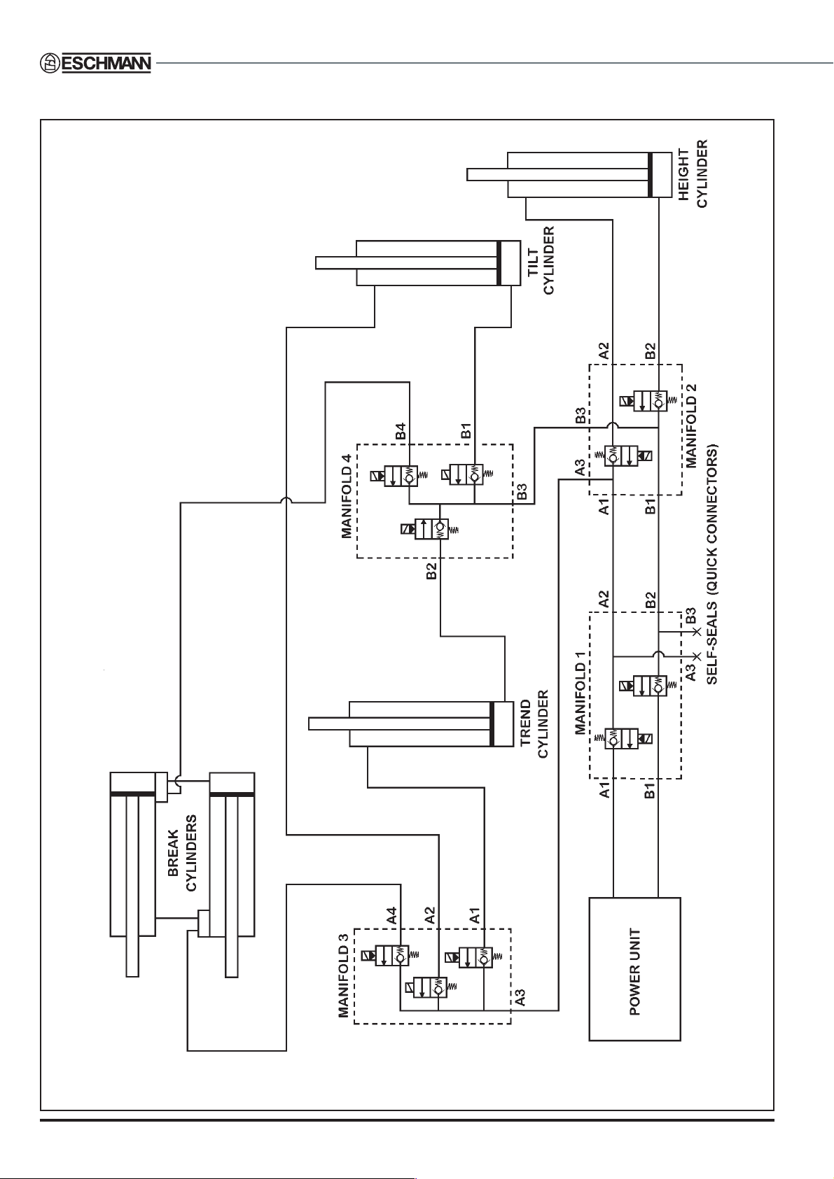
6. MAINTENANCE
Fig. 9 Hydraulic system - Schematic diagram

T-SM13h 17/40
RX500RX500
RX500RX500
RX500
OPERATION TABLE
6. MAINTENANCE
1 Manifold 1
2 Hydraulic connections
3 Power unit
4 Feed from reservoir
5 Powerunitelectricallead
6 Base distribution board
7 Base control board
8 Manifold 2
9 Trendelenburg cylinder
10 Tilt cylinder
11 Manifold 4
12 Manifold 3
Fig. 10 Hydraulic system - main components
For break cylinders see Fig.18
and for height cylinder see Fig.22.
The lateral tilt cylinder is also
shown in greater detail in Fig.19.

18/40 T-SM13h
HYDRAULIC SYSTEM
CAUTION
Scrupulouscleanlinessisessentialtoprevent
contaminationofthefluidinthehydraulicsystem.
Notes:
1 Use only Eschmann RX hydraulic oil, Part
No.699408, whichisobtainablefrom Eschmann
Equipment or their accredited agents.Replace
cap on oil container after use.
2 Whenreplacinghydrauliccomponentsall Banjo
fittings must be tightened to a torque setting
between 19 and 21 Nm.
3 The hydraulic system schematic diagram is
shown in Fig. 9 with the main components
illustratedinFig.10.Individualcylindersarealso
shown in the‘Removal and Installation’section
later in the manual.
General
6.17 If the table cannot be placed into the castor
position using the hand control, it may be necessary
to manually raise the table base. To raise the table
base, proceed as follows:
i Remove table base covers, see section 6.24.
ii Locate the Nyloc jacking nut at each corner of
the table base (see Fig.24, item 1) and wind
the nuts down evenly to raise the table base.
iii ReturnNylocjackingnutsto thepositionshown
in Fig.24 (i.e. flush with the top of the guide
pins) after corrective maintenance and replace
covers as section 6.25.
Topping-up the Hydraulic Reservoir
6.18 Top-up the hydraulic reservoir as follows:
i Set table to an appropriate height and remove
base covers as described in section 6.24.
ii Release the central column cover and remove
the upstand as described in section 6.28 and
release bezel.
iii Retract all cylinder rams (see note below)
before filling reservoir so that true oil level can
beestablished.Overfillingcouldcause damage
to reservoir.
iv Remove the filler cap from the hydraulic
reservoir and fill the reservoir with Eschmann
RXhydraulicoil (seeNote1above)until oil level
is 13 mm below the filler hole of the reservoir.
v Refit the filler cap on reservoir.
vi Refit the central column cover and upstand as
described in section 6.29.
vii Refitthebasecoversasdescribedinsection6.25.
Note:Hydrauliccylinder ramsareretractedwhen the
table top is positioned as follows, but care must be
takenwhenmovingthetableinto thispositiontoavoid
damage, sections will be very close to the floor :
• Minimum height and onto castors.
• Maximum extension achievable at the
minimum height set above.
• Maximum tilt achievable with table at the
minimumheightand extension setabove(tilt
tablesuchthat theright handsideis lowered
when viewed from long trunk end of table).
ADJUSTMENTS
Trendelenburg Microswitch
6.19 To check and adjust the Trendelenburg
microswitch (item 3, Fig. 11) proceed as follows:
i Ensure the table is on a level surface.
ii Using the hand control, move the table top to
the maximum Trendelenburg position.
iii Onthe handcontrol,pressthe‘auto level’button
and wait until the table top stops when level.
iv Using an inclinometer (on section radiopaque
top not the mattress), check the angle of the
long trunk section in the horizontal plane.
v If the angle is more than one degree out in either
direction adjust the Trendelenburg microswitch as
necessary, by releasing the adjusting screws (2,
Fig. 11) and moving the microswitch in the
appropriatedirection,retightentheadjustingscrews.
vi Repeat steps ‘ii-v’ until the long trunk section
stops level.
Lateral Tilt Opto
6.20 To check and adjust the lateral tilt opto (item
3, Fig. 12) proceed as follows:
i Ensure the table is on a level surface.
ii Using the hand control, tilt the table top to the
maximum lateral tilt position (left or right).
iii Onthe handcontrol,pressthe‘auto level’button
and wait until the table top stops when level.
iv Using an inclinometer (on section radiopaque
top not the mattress), check the angle of the
table top in the lateral plane.
v Iftheangleis morethan onedegreeoutineither
direction adjust the flag (item 4, Fig. 12) of the
lateraltilt optobyreleasing theadjustingscrews
(item 2, Fig. 12) and moving the flag in the
appropriatedirection,retightenadjustingscrews.
vi Repeat steps ‘ii-v’until the table stops level.
6. MAINTENANCE

T-SM13h 19/40
RX500RX500
RX500RX500
RX500
OPERATION TABLE
1 Break cylinder
2 Microswitch adjusting screws
3 Trendelenburg microswitch
4Yoke
5 Pivot pin
6 Pivot pin set screw
7 Tilt cylinder ram lock nut
8 Tilt cylinder ram
Fig. 11 Trendelenburg microswitch
1Yoke
2 Adjusting screws
3 Lateral tilt opto board
4 Lateral tilt opto flag
5 Top of column distribution board
Fig. 12 Lateral tilt opto detail
Break Microswitch
6.21 To check and adjust the break microswitch
(item 1, Fig. 13) proceed as follows:
i Ensure the table is on a level floor.
ii On the hand control, press the break
(extension) button and move the table top to
the maximum break (extension) position.
iii Onthe handcontrol,pressthe‘autolevel’button
and wait until the table top stops when level.
iv Using an inclinometer (on section radiopaque
top not the mattress), check that the long trunk
section is level, if it is not adjust the
Trendelenburg microswitch as detailed in
section 6.19.
v Using an inclinometer (on section radiopaque
top not the mattress), check the angle of the
short trunk section.
vi Ifthe angleis morethanonedegreeoutin either
direction adjust the break microswitch by
releasing the adjusting screws (items 4, Fig.
13) and moving the microswitch in the
appropriate direction, retighten the adjusting
screws.
vii Repeat steps‘ii-vi’ until the short trunk section
stops level.
1 Break microswitch
2 Long trunk assembly
3 Short trunk assembly
4 Adjusting screws
5 Tilt cylinder ram
6 Break cylinder ram
Fig. 13 Break microswitch
6. MAINTENANCE

20/40 T-SM13h
Tilt Switch
6.22 To adjust the tilt switch (item 4, Fig. 14)
proceed as follows:
i Ensure the table is on a level floor.
ii Onthehand control,press the‘autolevel’button
and wait until the table top stops when level
(check the long and short truck sections are
levelin bothdirections andadjust ifrequired as
detailed in sections 6.19 and 6.21).
iii On the hand control, press patient left
orientation button (button 1, Fig. 27).
iv On the hand control, press the reverse
Trendelenburg button (button 4, Fig. 27) and
move the table top to the maximum reverse
Trendelenburg position.
v Using an inclinometer (on the radiopaque top
not the mattress of the long trunk section),
check the angle of the table top. The angle
should be 35 degrees.
vi Onthehand control,press the break(extension)
buttonandcheckformovementoftheshorttrunk
section of the table top. If movement occurs,
adjust the tilt switch by releasing the adjusting
screws(item 3,Fig.14)andmovingthetiltswitch
in the appropriate direction to stop any
movement of the short trunk section with the
table top in the reverse Trendelenburg position.
vii After adjusting the tilt switch repeat actions (iv)
(v) and (vi) until there is no movement of the
short trunk section in the maximum reverse
Trendelenburg position.
1 Push button
2 Short trunk assembly
3 Adjusting screws
4 Tilt switch
Fig. 14 Tilt switch
REMOVAL AND INSTALLATION
General
6.23 All equipment in the base of the operation
table is accessible after the base covers have been
removed (see section 6.24). To gain access to
equipment located around the central column it is
necessary to remove the top-of-column covers (see
section 6.26) and release the central column cover
and upstand if required (see section 6.28).
RemoveTable Base Covers
6.24 Toremovetablebasecoversproceedasfollows:
i
Open doorsattheendsofthetablebase,seeFig.1.
ii At the long trunk end of the table base:
(a) Remove two screws (item 30, Fig.1) and
shoulderedwashersandpull thelongtrunkend
base cover (item 44, Fig. 2) from the base.
iv At the short trunk end of the table base:
(a) Removethe twoblackbuttoncoversfrom
the standby hydraulic push buttons (item 19,
Fig. 1) by gently pulling them off.
(b) Remove two screws (item 30, Fig.1) and
shouldered washers and pull the short trunk
end base cover (item 45, Fig.2) from the base.
v Remove the two base seals (item 42, Fig. 2).
Thecolumn seal(item 43,Fig. 2)can remainin
placeon theupstand unlessaccess isrequired
to the lower column (see section 6.28).
Note:When the hinged cover at the short trunk end of the
table is opened, or when the base cover is removed, a
microswitch operates to isolate the electrical supply to the
table. To operate the table with this cover removed, the
microswitch must be taped in the operated position.
InstallTable End Base Covers
Note: Before replacing covers check that all cables
andhydraulic pipesaresecured andthat theycannot
be pinched, chaffed or cut by any moving parts.
6.25 To install table end base covers proceed as
follows referring as required to Fig.1 and 2 :
i Check that all tools and discarded equipment
have been removed from inside table base
before installing base covers.
ii To install the short trunk end base cover:
(a) Press the two springs at the short trunk
end of the base and locate the short trunk base
coverinthesliderailsalongthesidesofthebase.
(b) Pushtheendcoverfullyhomeand secure
withtwoscrewsand shoulderedwashers,finally
replace the two push button covers.
6. MAINTENANCE
Table of contents
Other eschmann Medical Equipment manuals


Popular Medical Equipment manuals by other brands


Hillrom
Hillrom O-LPA Instructions for use

ICMedical
ICMedical 460 OPERATING AND INSTALLATION Manual

MTR+
MTR+ Dolito Operator's manual

Etac
Etac Immedia In2Sheet Instructions for use

Contec Medical Systems Co.
Contec Medical Systems Co. 22-01-CMS50D instructions

Smith & Nephew
Smith & Nephew REDAPT SURGICAL TECHNIQUE