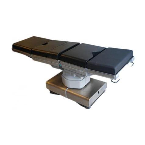
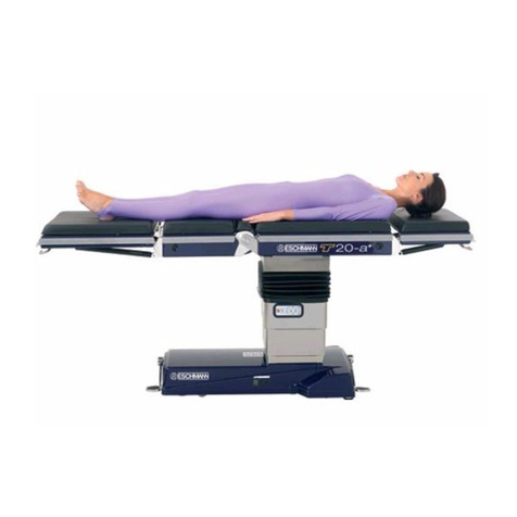
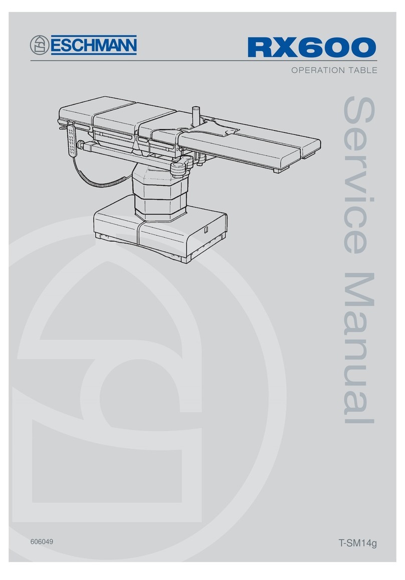
eschmann T20-a User manual

T20-a
OPERATION TABLE
Service manual
T-SM47j
111707

Service manual
Preliminary
Information
Technical data
Technical
description
Safety notes
Maintenance
Part removal
adjustment
replacement
Read these Instructions before use
Keepthese‘Instructions’inasafeconvenientplaceforfuturereference.Readinconjunction
with the Publications detailed in Section 1.1.
Eschmann After Sales Service Department
The Eschmann After Sales Service Department is staffed and equipped to provide advice and
assistance during normal office hours.To avoid delays when making enquiries, please quote the
Modeland SerialNumberofyour OperationTable whichisshownon theSerialNumberplate, the
location of which is shown below. Please ensure you include all alpha and numeric digits of the
Serial Number.
For further information visit www.eschmann.co.uk
All correspondence relating to the after sales service of Eschmann Equipment to be addressed to :
UK Customers
Eschmann Equipment, Peter Road, Lancing, West Sussex BN15 8TJ, England.
Tel: +44 (0) 1903 765040. Fax: +44 (0) 1903 875711.
Overseas Customers
Contact your local distributor. In case of doubt contact Eschmann Equipment.
Patents and Trade marks
The ESCHMANN name and logo are registered trade marks of Eschmann Holdings Limited.
“Eschmann Equipment” is a trading name of Eschmann HoldingsLimited.
“T20-a”is atrademarkofEschmannHoldingsLimited.
Patents: WorldwidePatentsPending.
Copyright © 2005 Eschmann Holdings Limited
All rights reserved. This booklet is protected by copyright. No part of it may be reproduced, stored in a
retrieval system or transmitted in any form or by any means, electronic, mechanical, photocopying,
recording or otherwise without written permission from Eschmann HoldingsLimited.
The information in this publication was correct at the time of going to print. The Company, however,
reservesthe rightto modifyorimprove theequipment referredto.
The CE marking affixed to the product certifies that it complies with the
EuropeanMedical DevicesDirective93/42/EEC andrelatedlegislation.
T-SM47j July 2005
The Serial Number
plate is located here

T-SM47j P3/54
T20-a
OPERATION TABLE
CONTENTS
1.0 Preliminary information
1.0 Preliminary information . . . . . . . . . . . . . . . . . . . 5
2.0 Technical data
2.1 Weights . . . . . . . . . . . . . . . . . . . . . . . . . . . . . . . 8
2.2 Dimensions . . . . . . . . . . . . . . . . . . . . . . . . . . . . 8
2.3 Movements . . . . . . . . . . . . . . . . . . . . . . . . . . . . 8
2.4 Table loading . . . . . . . . . . . . . . . . . . . . . . . . . . . 8
2.5 Electrical . . . . . . . . . . . . . . . . . . . . . . . . . . . . . . 8
2.6 Classification and symbology . . . . . . . . . . . . . . 9
2.7 Use in conjunction with other equipment . . . . . . 9
2.8 Standards compliance . . . . . . . . . . . . . . . . . . . . 9
2.9 Environmentalconditions . . . . . . . . . . . . . . . . . . 9
3.0 Technical description
3.1 Powersupply assembly . . . . . . . . . . . . . . . . . . 13
3.2 Control electronics . . . . . . . . . . . . . . . . . . . . . . 13
3.2.1 Overview . . . . . . . . . . . . . . . . . . . . . . . . . . 13
3.2.2 Handset overview . . . . . . . . . . . . . . . . . . . . 14
4.0 Safety warnings
4.1 ‘Service position’ . . . . . . . . . . . . . . . . . . . . . . . 16
4.2 Lifting . . . . . . . . . . . . . . . . . . . . . . . . . . . . . . . 16
4.3 M10 trunk screw removal . . . . . . . . . . . . . . . . 16
4.4 Trend andtilt actuatorremoval . . . . . . . . . . . . . 16
4.5 Working with mains voltage . . . . . . . . . . . . . . . 16
4.6 Gas springs . . . . . . . . . . . . . . . . . . . . . . . . . . . 16
4.7 Hot parts on PCAs . . . . . . . . . . . . . . . . . . . . . 16
4.8 Biologicalcontamination . . . . . . . . . . . . . . . . . 16
4.9 Connection of leads . . . . . . . . . . . . . . . . . . . . . 16
4.10 Leaking batteries . . . . . . . . . . . . . . . . . . . . . . . 16
5.0 Maintenance
5.1 Powersupply assembly . . . . . . . . . . . . . . . . . . 17
5.2 Table faultfinding . . . . . . . . . . . . . . . . . . . . . . . 17
5.2.4 Break motion control . . . . . . . . . . . . . . . . . 17
5.2.5 Trunk section connector blocks . . . . . . . . . 17
5.3 Fuse location . . . . . . . . . . . . . . . . . . . . . . . . . . 17
5.4 Service schedule and safety check . . . . . . . . . 18
6.0 Part removal/adjustment/
replacement
6.1 General . . . . . . . . . . . . . . . . . . . . . . . . . . . . . . 20
6.2 Table base and column covers . . . . . . . . . . . . 20
6.2.2 Base covers . . . . . . . . . . . . . . . . . . . . . . . . 20
6.2.2.1 Removal of base covers . . . . . . . . . . 20
6.2.2.2 Replacing base covers . . . . . . . . . . . 21
6.2.3 Access to column . . . . . . . . . . . . . . . . . . . . 21
6.2.3.2 Lower column access . . . . . . . . . . . . 21
6.2.3.3 Lower-mid column access . . . . . . . . 21
6.2.3.4 Upper-mid column access . . . . . . . . 21
6.2.3.5 Top of column access . . . . . . . . . . . . 23
6.2.4 Telescopic covers . . . . . . . . . . . . . . . . . . . . 23
6.2.4.1 Removal of telescopic covers . . . . . . 23
6.2.4.2 Refitting the telescopic covers . . . . . 23
6.2.5 Bellows . . . . . . . . . . . . . . . . . . . . . . . . . . . . 23
6.2.5.1 Removalof thebellows . . . . . . . . . . . 23
6.2.5.2 Replacingthebellows . . . . . . . . . . . . 24
6.3 Table base components . . . . . . . . . . . . . . . . . . 24
6.3.2 Batteries . . . . . . . . . . . . . . . . . . . . . . . . . . . 24
6.3.3 Pedal dampers . . . . . . . . . . . . . . . . . . . . . . 24
6.3.4 Frontwheels . . . . . . . . . . . . . . . . . . . . . . . . 25
6.3.5 Castors . . . . . . . . . . . . . . . . . . . . . . . . . . . . 25
6.3.5.1 Castorassembly . . . . . . . . . . . . . . . . 25
6.3.5.2 Castorwheels . . . . . . . . . . . . . . . . . . 25
6.3.6 Brakepads . . . . . . . . . . . . . . . . . . . . . . . . 25
6.3.7 Castorpillar bushes . . . . . . . . . . . . . . . . . 29
6.3.8 Pedalspindlebushes . . . . . . . . . . . . . . . . 29
6.3.9 Lifting roller assembly.. . . . . . . . . . . . . . . . 29
6.3.10 Pedal catchblock . . . . . . . . . . . . . . . . . . . 29
6.3.11 Pedal anti-skid pads . . . . . . . . . . . . . . . . . 29
6.3.12 Pedalcatch pawlandspring . . . . . . . . . . . 29
6.4 Tablecolumncomponents . . . . . . . . . . . . . . . . 30
6.4.2 Trendelenburgactuator . . . . . . . . . . . . . . . . 30
6.4.3 Tilt actuator . . . . . . . . . . . . . . . . . . . . . . . . . 30
6.4.4 Telescopic columnassembly . . . . . . . . . . . . 30
6.4.5 Tilt &Trendelenburgmotor . . . . . . . . . . . . . . 32
6.4.6 Tilt bush . . . . . . . . . . . . . . . . . . . . . . . . . . . 32
6.4.7 Trendelenburgbush . . . . . . . . . . . . . . . . . . . 32
6.4.8 Bearing pads . . . . . . . . . . . . . . . . . . . . . . . . 32
6.5 Table sections . . . . . . . . . . . . . . . . . . . . . . . . . 33
6.5.1 Head and leg section . . . . . . . . . . . . . . . . . 33
6.5.1.1 Guidepins . . . . . . . . . . . . . . . . . . . . 33
6.5.1.2 Gassprings . . . . . . . . . . . . . . . . . . . 33
6.5.1.3 Topcover . . . . . . . . . . . . . . . . . . . . . 33
6.5.1.4 Gasspring release head/pin . . . . . . . 33
6.5.1.5 Gasspring release handle . . . . . . . . 35
6.5.1.6 X-raytranslucent top . . . . . . . . . . . . 35
6.5.2 Trunksections . . . . . . . . . . . . . . . . . . . . . . . 35
6.5.2.1 Traversemotor . . . . . . . . . . . . . . . . . 35
6.5.2.2 Traversedrive belt . . . . . . . . . . . . . . 36
6.5.2.3 Breakmotor . . . . . . . . . . . . . . . . . . . 36
6.5.2.4 Breakgearbox . . . . . . . . . . . . . . . . . 36
6.5.2.5 Side rails . . . . . . . . . . . . . . . . . . . . . 39
6.5.2.6 Top covers . . . . . . . . . . . . . . . . . . . . 39
6.5.2.7 Pushbutton components . . . . . . . . . 39
6.5.2.8 Traverserodbearing . . . . . . . . . . . . . 39
6.5.2.9 Drivebeltguide bearing . . . . . . . . . . 41
6.5.2.10 Attachment blocks . . . . . . . . . . . . . . 41
6.5.2.11 Black tops . . . . . . . . . . . . . . . . . . . . 41
6.6 Electricalcomponents . . . . . . . . . . . . . . . . . . . 41
6.6.2 Three actuator PCA . . . . . . . . . . . . . . . . 42
6.6.3 Fouractuator PCA . . . . . . . . . . . . . . . . . 42
6.6.4 Infraredreceiver PCA . . . . . . . . . . . . . . 42
6.6.5 Powersupply assembly . . . . . . . . . . . . . 43
6.6.6 Traversemotor . . . . . . . . . . . . . . . . . . . . 43
(continued over page)

P4/54 T-SM47j
6.6.7 Breakmotor . . . . . . . . . . . . . . . . . . . . . . 43
6.6.8 TiltandTrendelenburgmotors . . . . . . . . 43
6.6.9 Telescopic columnassembly . . . . . . . . . 43
6.6.10 Breakpotentiometer loom . . . . . . . . . . . 43
6.6.11 Tiltpotentiometer loom . . . . . . . . . . . . . 43
6.6.12 Trendelenburgpotentiometer . . . . . . . . . 43
6.6.13 Heightpotentiometerloom . . . . . . . . . . . 43
6.6.14 Traverse motorloom& m’switches . . . . . 45
6.6.15 Connector blocks & looms . . . . . . . . . . . 45
6.6.16 Switch & accessory panel looms . . . . . . 45
6.6.17 Columnenergy chainandloom . . . . . . . 45
6.6.18 Breakgearbox loom . . . . . . . . . . . . . . . . 46
6.6.19 Batteries, table & handset . . . . . . . . . . . 46
6.6.20 Fuses . . . . . . . . . . . . . . . . . . . . . . . . . . 46
6.6.21 Tableinfrared codechange . . . . . . . . . . 46
6.6.22 Infraredhandset code change . . . . . . . . 46
6.6.23 Handsetservice . . . . . . . . . . . . . . . . . . . 47
6.6.24 Processor PCA . . . . . . . . . . . . . . . . . . . 47
6.6.25 Standbypanel andloom . . . . . . . . . . . . 47
6.6.26 Batterymanagementreconditioning . . . . 47
6.7 Function tests . . . . . . . . . . . . . . . . . . . . . . . . . 47
6.7.1 Batteries . . . . . . . . . . . . . . . . . . . . . . . . 47
6.7.2 Batterycharger . . . . . . . . . . . . . . . . . . . 47
6.7.3 Cordedhandset . . . . . . . . . . . . . . . . . . . 47
6.7.4 Infraredhandset . . . . . . . . . . . . . . . . . . . 47
6.7.5 Footswitchcontrol . . . . . . . . . . . . . . . . . 47
6.7.6 Standbycontrol panel . . . . . . . . . . . . . . 47
6.7.7 Sections(head andleg) . . . . . . . . . . . . . 47
6.7.8 Basepedals . . . . . . . . . . . . . . . . . . . . . . 48
6.7.9 Cycle of movements . . . . . . . . . . . . . . . 48
6.8 Accessories . . . . . . . . . . . . . . . . . . . . . . . . . . . 48
Figures
1.0 Identification of main parts . . . . . . . . . . . . . . . . . 6
2.1 Major dimensionsandmovements . . . . . . . . . . 10
2.2 Maximum patientweights . . . . . . . . . . . . . . . . 11
2.3 Maximum patientweights . . . . . . . . . . . . . . . . 12
3.1 Schematic diagrams . . . . . . . . . . . . . . . . . . . . 15
6.1 Tablecoversgeneralarrangement . . . . . . . . . . 22
6.2a Tablebasegeneralarrangement (ext’lcatch) . . 26
6.2b Tablebasegeneralarrangement (int’lcatch) . . . 27
6.2c Tablebase generalarrangement(int’lcatch
andincreasedheight) . . . . . . . . . . . . . . . . . . . . 28
6.3 Tablecolumngeneralarrangement . . . . . . . . . . 31
6.4 General arrangement,head& legsection. . . . . 34
6.5 Tablelongtrunkgeneral arrangement . . . . . . . . 37
6.6 Tableshort trunk generalarrangement . . . . . . . 38
6.7 Tabletraversegeneralarrangement . . . . . . . . . 40
6.8 Table basemainelectrical components . . . . . . 42
6.9 Handset buttonfunctions andseriallabels . . . . 44
6.10 Oldand newinfraredHandsetbuttons . . . . . . . 44
A1 T20-a Schematic diagram - Base Section . . . . 51
A2 T20-aSchematic diagram-Pedestal Section . . 52
A3 T20-a Schematic diagram-Trunk Section . . . . 53
Appendix 1
Torqueconversions . . . . . . . . . . . . . . . . . . . . . . . . . . 49
Appendix 2
Applicationsoftware guide . . . . . . . . . . . . . . . . . . . . . 50
Appendix 3
T20-aTableschematics . . . . . . . . . . . . . . . . . . . . . . . 51
Appendix 4
Electrical safety checks . . . . . . . . . . . . . . . . . . . . . . . 54

T-SM47j P5/54
T20-a
OPERATION TABLE
1.0 PRELIMINARY INFORMATION
WARNING
Before servicing this operation table the
engineer should be familiar with all the
warnings and cautions contained within the
‘Instructions for use’ detailed in section 1.1.
This service manual does not provide details
of how to operate the table nor does it provide
information on the symbols and warning signs
provided on the table. All this information is in
the‘Instructions foruse’supplied withthe table.
Additional copies of the ‘Instructions for use’
can be obtained from Eschmann Equipment.
Only qualified and trained engineers should
service or maintain this operation table to
ensure that all the built-in safety features are
not compromised.
1.1 This ServiceManualshouldbereferredto for details
oftheT20-aPoweredOperationTable,SerialNumber(SN)
T2AA3A0000 orabove:
REFT20-223-2301* & T20-108-2301*
REFT20-221-2301 & T20-106-2301
REFT20-221-2101 & T20-106-2101
*These models haveDenyer styleaccessorysiderails.
The related publications listed below provide additional
information.
T-IM102 (111701) -Instructions foruse
T-IPL35 (111706) - Illustrated parts list
T-IM94 (111012) -‘T’SeriesApplicationsoftwaremanual
T-IM56 (698907)-Generalaccessory leaflet
The number in brackets above, is the part number for that
publication.
1.2 ‘Instructions for use’ and ‘Service manuals’ should
be readily accessible for reference prior to and when
operating,cleaning,servicing,or,maintaining the operation
table.
1.3 Thetable and allaccessories arenot suppliedsterile
therefore the table and all accessories should be cleaned
and disinfected in line with hospital practice and the
informationsuppliedinthe‘Instructions for Use’beforeuse.
1.4 The manuals listed above and the Application
software,areavailabletoorderfromEschmannEquipment,
see inside front cover for address details.
1.5 Make sure that routine servicing is carried out as
detailedinthe serviceschedule,section5.4,by Eschmann
trained or accredited engineers.
1.6 Theservice scheduleprovided inthis manualdetails
a program of maintenance work to be carried out at six
monthly intervals, refer to the applicable section of this
manualfordetailsofhowtoperformthese variousfunctions.
Any special adjustments required for components are
detailed in the part replacement (section 6.0) for that item
tosaveduplication.Asroutinethe Service Scheduleshould
be followed in the event of an additional service due to a
faultdevelopingwithanyaspectofthe table, thiswill ensure
that all aspects of the table are covered.
WARNING
Ensure that the correct screw torque settings
are used as detailed within this manual to
ensure safety and that parts are not damaged.
1.7 Throughout this manual there are recommended
torque settings for many of the screws. In the main, these
are only provided on the illustrations. Ensure that these
arecheckedandthecorrecttorquesettingsare used where
specified.These areprovidedtoensure safety(i.e.screws
are tightened correctly) and that components are not
damaged by excessively high torques.
1.8 Fig. 1.0 identifies the main parts of the T20-a
operationtable.
1.9 The tablecanbeplacedinto a ‘ServicePosition’that
provides easy access to components within the ‘top of
column’area (ensuretableis switched‘off’beforeopening
top). To achieve this position first note the safety warning
insection 4.1.Removeasmuch aspossiblefromthe table
top (e.g. leg and head sections, accessories and
mattresses etc.). Remove the top of column steel covers
(items13 and 14ofFig.6.1). RemovethefourM10 screws
(each side) that secure the trunk sections to the pedestal
(not the M6 cap head screws that can be seen passing
throughthe oilitebushesoneach side)andallow thetrunk
section to pivot (short trunk down) about the oilite bush
pivots(item 16, Fig.6.3).Extreme careshouldbe takenat
all times with the table in this position, especially during
transition into and out of the ‘Service Position’. Use tool
numberT2203to maintain contactbetweenthe connector
blocksifrequired when thetableisinthe‘Service Position’.
Whenreturningthetableoutofthe‘ServicePosition’ensure
the eight M10 screws are tightened to the correct torque
and that the covers are replaced.
1.10 The ‘Instructions for use’ (provided with the table)
containall thecleaning,disinfection andcareinstructions,
consultthis fortheseaspects astheyare notduplicatedin
this manual. CAUTION
Continued use of the table batteries when
‘criticallylow’candamage thebatteries. Charge
batteries regularly to maintain peak
performance. Do not remove the table from
charge until both charging LED’s are ‘green’to
avoid false battery level indication on the
handset.

P6/54 T-SM47j
Fig. 1.0 Identification of main parts
NOTE:The table illustrated hasexternalpedallocking catches. Some
tableshaveinternallockingcatches,see section 6.2 and 6.3 fordetails.

T-SM47j P7/54
T20-a
OPERATION TABLE
Key to Fig. 1.0
1 Head section
2 Long trunk section
3 Short trunk section
4 Leg section
5 Leg section gas spring
6 Short trunk section release button
7 Long trunk section release button
8 Batteryfuses
9 Wheel foot pedal
10 Head section release bar
11 Head section gas spring
12 Standby control panel
13 Base
14 Pedestal
15 Castor foot pedal
16 Leg section release bar
17 Mains fuses
18 Connection socket for mains (ONLY use Eschmann mains cord, Part No. 391177)
19 Main battery charging state LED:
Red = Mains ‘on’, batteries in ‘bulk’ charge
Amber = Mains ‘on’, batteries in ‘top-up’ charge (duration 2 hours)
Green = Mains ‘on’, batteries in ‘trickle’ charge (i.e. fully charged)
20 Standby battery charging state LED (colour code as main battery above)
21 Main table ‘On/Off’switch ( = Off, = On)
22 Connection socket for Eschmann footswitch (ONLY)
23 Table ‘On’ LED (green)
Bright = Table in use, micro-controllers active
Dim = Table ready for instant use but in battery save (sleep) mode
24 Connection socket for Eschmann handset (ONLY)
25 Head and leg section end blocks (use to stow UK handset)
26 Accessory side rails (can also be used to stow handset*)
27 Standby battery switch
* Clip on handset must match side rail type, see ‘Instructions for Use’.
Note: For location of the Serial Number plate see inside front cover.

P8/54 T-SM47j
2.0 TECHNICAL DATA
2.1 Weights
The nominal weights of the standard table components
are listed below (for 50mm mattresses):
Leg section (without mattress) .. ..11.50kg
Leg section mattress .. .. .. .. 2.75kg
Headsection (withoutmattress) .. .. 7.75kg
Head section mattress .. .. .. 2.00kg
Table (baseandcolumnonly) .. 192.00kg
Long and short trunk assembly* .. 55.75kg
Long and short trunk mattress .. .. 7.25kg
Total weightstandardtable .. .. .. 279kg
Lightweight leg section.. .. .. .. 4.50kg
Footrest(incl. mattress) .. .. .. 7.00kg
Widthextender (incl.mattress) .. .. 6.00kg
Perinealinstrument tray .. .. .. 3.00kg
* (without mattress)
2.2 Dimensions
The following are the nominal major dimensions of the
standard table (with head and leg sections fitted) and
includethe 50mm mattressandsiderails ifapplicable(see
Fig. 2.1 for illustration, the number in brackets after the
item details which part):
Overalllength (2) .. .. .. 2102mm
Maximumheight (4) .. .. .. 1120mm*
Minimumheight (5) .. .. .. 720mm*
Maximumtop traverse(2) .. .. 250mm
Overallwidth (6) .. .. .. 600mm
Sidebars(Denyer) .. .. .. 37.8 x 5.5mm
* 5mm less for Serial Numbers prefixed T2AAor T2AB
2.3 Movements
Thefollowingtable movementsaremaximumsandcannot
be assumed to be available in all combinations of table
positioning (see Fig. 2.1 for illustration, the number in
brackets after the item details which part). For example,
with the table in its normal configuration and at minimum
height the maximum Trendelenburg and leg section
movements cannot be achieved due to the proximity of
thefloor.Similarly withalarge amountoftilt set,maximum
Trendelenburg cannotbeachieved.
Max.Trendelenburg (1) .. .. .. 35°
Max.reverseTrendelenburg (1) .. .. 35°
Max.extension (4) .. .. .. .. 230°
Max.flexion (4) .. .. .. .. .. 90°
Head section (5) .. .. .. .. ±45°
Leg section (3) .. .. .. .. -100° +55°
Max. lateral tilt (7) .. .. .. .. ±18°
2.4 Table loading
Seemaximum patientweightdistribution chartsinFig. 2.2
and 2.3 for various table positions and orientations.
Maximum section loading is stated on each item and is
detailed below for reference:
Legsection .. .. 44kg
Head section .. .. 22kg
For accessories the maximum loading is stated on each
itemanddetailedintheUserHandbooksupplied with them.
Forspecificnotesonthe obese patientsee the ‘Instructions
for Use’.
2.5 Electrical
2.5.1 Antistatic requirements
The table has an antistatic pathway from the table top,
through an internal resistor, to the castors.
CAUTION
To complete and maintain the antistatic
pathway the table must be used on an
electrically conductive or antistatic floor and
with mattresses supplied by Eschmann
Equipment.
2.5.2 Batteries
Table base:
Mainbatteries**:
Two, 12V 10.0Ah, sealed lead acid
Backupbatteries**:
Two, 12V1.2Ah,sealed leadacid
(seebatterydisposal cautioninthe‘Instructionsfor Use’)
Infraredhandset:
Two, 1.5V size AA Alkaline (Note: Must only be
changedinaccordance with thenotesinthe section
6.6.19.2toensurethe IPratingisnot compromised).
2.5.3 Internal battery charger**
Input
100-240V a.c. 2.4A (max) 50-60Hz
Output
29.2Vd.c. 2A(max.)when chargestateLED
red or orange, 27.6V d.c. when charge state
LED green
2.5.4 Fuses
2.5.4.1
External fuses
Mains input fuses (item 17, Fig. 1.0)
2 x T4A(5 x 20mm) 250V
Battery fuses (item 8, Fig. 1.0)
2 x T20A(6.35 x 32mm) 500V

T-SM47j P9/54
T20-a
OPERATION TABLE
Note:Therighthandfuseislinkedtothemainbatteries
andthelefthandfuse(i.e.nearesttothebackupbattery
switch) is linked to the backup batteries.
Mains plug fuse
.. .. 10A(typeisdependentonplug
which may have been changed from that originally
supplied)
2.5.4.2
Internalfuses**
(onlyaccessiblebyengineer)
Battery fuses** (joining each battery pair)
2 x 30A blade type* (1 per battery pair)
2.5.5 Duty cycle
Thissymbolis usedtoindicatethetable’sdutycycle
which, in the worst case, is ‘60s : 600s’, the ratio of the
operating time to the sum of the operating time and the
ensuing interval (see note below). Each motor drive has
its own duty cycle and this is dependent on loading and
table position as detailed below.
Trendelenburg 1 : 4 (60s : 240s) at a maximum torque of
417Nm (e.g. 135kg load offset 31cm from the
fulcrum, or a 300kg load offset 14cm from the
fulcrum. Where this load is the patient and
accessoriesweightandtheoffsetishowfartheloads
centre of gravity is, from the centre of the column).
Traverse 1 : 4 (60s : 240s) when the table is
horizontal and at the maximum load of 300kg, or at
17.5°with apatientweight of 225kg,orat 35°witha
patient weight of 150kg.
Break 1 : 10 (60s : 600s) at maximum patient
weight of 300kg.
Height 1 : 4 (60s : 240s) at maximum patient
weight of 300kg (not offset).
Tilt 1 : 4 (60s : 240s) at maximum patient
weight of 300kg.
Note:Theduty cyclesaboveare allforthe worstcase(i.e.
maximum loads). For reduced loading the above duty
cycles can be increased.
2.6 Classification and symbology
Allthesymbolsused onthis tableareshownandexplained
inthe‘InstructionsforUse’.Thesedetailthesafetycategory
andclass ofthistableas markedonthe table orsectionby
the use of these symbols.
2.7 Use in conjunction with other
equipment
2.7.1 Electrosurgical equipment (h.f.)
TheT20-aoperation tablehasbeen designedtominimise
the possibility of accidental electrosurgery burns and can
be used in conjunction with electrosurgical equipment.
However, contact with any metal surfaces (e.g. table side
bars, or other equipment etc.) can cause burns during
electrosurgery and must be avoided.
2.7.2 Defibrillation equipment
With the mains cord attached the equipment has
defibrillator proof applied parts with type BF protection
against electric shock.
2.7.3 Other
When the T20-a is used in conjunction with other infrared
controlled devices, their controllers should be checked to
ensurethatno interferencebetweenthemandtheT20-ais
possible, prior to surgical intervention. Also see the
‘Instructions for Use’.
2.8 Standards compliance
The table has been designed and built to comply with the
followinginternational standards:
BS EN 60601-1: 1990 (issue 2, October 1997)
BS EN 60601-1-2: 1993
BS EN 60601-2-46: 1998
BS EN 60601-1-4: 1997
2.9 Environmental conditions
2.9.1 Operating environment
The table has been designed to operate in the following
environment:
Temperaturerange .. .. 10°C to +40°C
Pressure range .. .. .. 69KPato 106KPa.
Humidity range .. .. .. 30% to 75% RH
non-condensing.
2.9.2 Transport & storage environment
The table can be transported and stored safely, in the
followingenvironment:
Temperaturerange .. .. -30°C to +50°C
Pressure range .. .. .. 69KPa to106KPa
Humidity range .. .. .. 30% to 90% RH
non-condensing.
** NOTE: Items marked ** are to be changed with caution. During change or
replacement they must only be disconnected for a maximum of 60 seconds. If
batterypowerisremovedfromthetableforlongerthanthisthenreconditioning
of the battery management system must be carried out, see section 6.6.26.

P10/54 T-SM47j
Theseare maximummovements foreachaspect, theymay notbeavailable incertain combinations(e.g.maximum
tilt and maximum Trendelenburg). Movements that could cause damage cannot be catered for (e.g. position of the
leg section). Fig. 2.1 Major dimensions and movements
1
2
3
4
5
6
7
(seesection2.2)
(seesection2.2)

T-SM47j P11/54
T20-a
OPERATION TABLE
Fig. 2.2 Maximum patient weight v table position graphs

P12/54 T-SM47j
Fig. 2.3 Maximum patient weight v table position graphs

T-SM47j P13/54
T20-a
OPERATION TABLE
3.0 TECHNICAL DESCRIPTION
See Fig. 3.1 andAppendix 3 for schematic diagrams.
3.1 Power supply assembly
This assembly (Part number 111765) which is located in
thetable base,hasno userserviceableparts andmustbe
changed as a complete unit. The assembly includes, a
Batterycharger loom,aBattery chargermodule,a Battery
management PCA, a Battery connector loom, a Chassis
plate, two Battery support brackets, a Switch, two Fuses
(32 x 6.35mm 20A‘T’type), two Fuse holders, two battery
pairs and all connections, cable ties and screws etc.
3.2 Control electronics
3.2.1 Overview
Thecontrolelectronics fortheT20-ais distributed between
two PCA’s (the ‘4 actuator PCA’ and the ‘3 actuator PCA’).
These two PCA’s contain three distinct microprocessor
daughter PCAs (two on the ‘4 actuator PCA’ and one on
the ‘3 actuator PCA’).
The ‘4 actuator PCA’ (111524) is located on the column
and includes the ‘main controller’ and the ‘4 actuator
controller’. Each of these ‘controllers’ consists of a
‘microprocessordaughter PCA’(111526)which havetheir
control electronics on the ‘4 actuator PCA’.
The ‘Three actuator PCA’ (111525) is located in the long
trunk section of the table and contains the ‘3 actuator
controller’, another ‘microprocessor daughter PCA’
(111526)with its controlelectronicson the‘Threeactuator
PCA’.
3.2.1.1 Microprocessor daughter PCAs
ThedaughterPCAsconsistofa Motorola MC68HC912B32
micro controller, a watchdog circuit, an RS232 line driver
and an SPI UART and RS485 line driver. All the micro
controllers on the T20-a require these components. The
RS232communicationscanbeused to providea telemetry
link to custom software running on a PC. Once fitted to
theirrespective controllerboardsthe microcontrollersare
programmed with the appropriate software application.
There is a ‘main controller application’ (110442) and an
‘actuator controller application’ (110443). Both the 4-
actuator and 3-actuator are programmed with the same
‘actuator controller application’ (110443). A configuration
file is then downloaded to each micro controller that
specifies which controllers are present on which board. It
ispossibleto configure anyactuatortoanyboard,however
the configuration of the electronics is specific to each
actuator.
3.2.1.2 The ‘main controller’
The ‘main controller’provides the control and supervisory
functions for the table. This consists of the interface to the
infrared handset, corded handset (via RS232), footswitch
andstandby panel.Italso controlsthetable powerLED.
The main controller communicates with the two actuator
controllers (one of which is co-located on the 4 actuator
PCA) by means of an RS485 multi-drop bus. This system
enables multiple slave controllers to be attached at any
time. The main controller issues a health check poll
message to each of the actuators (up to four of which can
be controlled by the single PCA) to ensure that they are
functioningcorrectly.
When a command is received from any of the user-input
devices the main controller issues the appropriate
movementcommandsto therequiredactuator(oractuator
groups in the case of combined movements).
3.2.1.3 The ‘4 actuator PCA’
The ‘4 actuator PCA’ is responsible for movement of four
actuators on or within the table’s column. These are the
‘top and bottom height actuators’ inside the column
assembly,the‘Trendelenburgactuator’andthe‘Tiltactuator’
mounted on the column. A number of signals control the
movement of each actuator.
APWMsignal isusedto setthespeed ofthemotor; digital
signals control direction (forward/reverse), a digital signal
enables the drive circuit and another digital signal effects
a brake on the motor by shorting the windings together.
Theelectronicsprovideadigitalfaultsignaltoindicatewhen
thereisa problem withthe controlcircuit,oranovercurrent
situationhasoccurred. Ananaloguesignal is alsoprovided
onallbut the‘bottomheightactuator’.Theanalogue signal
onthetopheightactuatoristheoutputfromapotentiometer
thatindicatesthecombinedpositionofthe height actuators.
Although the column contains two motors, there is only a
single potentiometer to indicate the height of the column.
Thisanalogue signalisfed to the‘topheight actuator’; the’
bottom height actuator’is effectively slaved to the top.
3.2.1.4 The ‘Three actuator PCA’
The ‘Three actuator PCA’ is responsible for movement of
the three actuators within the tables long and short trunk
sections. These are the ‘left break actuator’, ‘right break
actuator’ and the ‘traverse actuator’. These actuators are
controlled by the same signals as on the ‘4 actuator PCA’.
Intermsoffeedback,boththe‘leftandrightbreakactuators’
have potentiometers and the ‘traverse actuator’ has limit
switches which open when the long trunk reaches either
end of its movement. The ‘left and right break actuators’
are independently controlled to move at a set speed and
to maintain a minimum deviation between them.

P14/54 T-SM47j
3.2.2 Handset overview
Therearetwoversionsofhandset,a cordless type(infrared
handset) with an infrared emitter powered by 2 AA cells
anda cordedversion(corded handset) withanRS232 link
to the main processor on the ‘4 actuator PCA’. The latter
versionderives itspower fromtheT20-a.
3.2.2.1 Infrared handset
The 4 x 5 matrix keyboard is decoded using a proprietary
keyboard decoder. This device is powered down and
remains dormant until a key is pressed causing its clock
oscillatortobeinitialised.Thekeyisdecodedandthe38kHz
modulated signal is fed to the infrared LED via a FET. The
whole system is powered via 2 AAbatteries
3.2.2.2 Corded handset
The 4 x 5 matrix keyboard is decoded using a proprietary
keyboard decoder. This device is powered down and
remains dormant until a key is pressed causing its clock
oscillatortobeinitialised.Thekeyisdecodedandthe38kHz
modulatedsignal isfedto aPICprocessor.Theprocessor
decodestheoutputfromthekeyboard decoder intoRS232.
This output is fed to an RS232 line driver. The corded
handset’s power is supplied directly from the T20-a, 5V
powersupply.The handset containsaDC-DC converter to
supply3.3V forthe keyboard decoder.There areindicator
LED’sto show thecharge status ofthe tablebatteries (main
and standby).

T-SM47j P15/54
T20-a
OPERATION TABLE
PROCESSOR
CONTROL FET DRIVERS
MOTOR
POSITIONAL
FEEDBACK
OVER
CURRENT
MANAGER
CONTROL FROM
HOST MICRO
AXIS TILT
AXIS TREND
AXIS HEIGHT 1
AXIS HEIGHT 2
POSITION ENCODERS AND
ANCILLARIES
OVER CURRENT MANAGERS
CONNECTORS
INC:
CONNECTORS & INTERFACES
MICRO CONNECTORS
POWER
MANAGEMENT
AXIS BREAK RIGHT
AXIS BREAK RIGHT
AXIS TRAVERSE POSITION
MONITORS
OVER CURRENT
MANAGERS
CONNECTORS
POWER
MANAGEMENT
PROCESSOR COMMUNICATIONS
INTERFACE
CONNECTOR 64 WAY
4
12
44
Keyboard Encoder
Infrared Driver / Emitter
BatteryKeyboard
Power Management
Keyboard Encoder
Connector/LeadKeyboard
Power Management
Processor
RS232 Decoder/Driver
Basic control and feedback - all actuator drivers
Four Actuator PCA
Three actuator PCA
Processor PCA
Handset corded version
Handset remote version
Fig. 3.1 Schematic diagrams

P16/54 T-SM47j
4.0 SAFETY WARNINGS
4.1 ‘Service position’
When the four M10 screws (each side) that secure the
trunk sections to the pedestal are removed, to place the
table in the ‘Service position’ as detailed in section 1.9,
always take extreme care (and ensure table is switched
‘off’ before tilting top into or out off the ‘Service position’).
WhentheM10screwsareremovedthe table trunksections
maytiltdramatically unless thesectionsarefullysupported
duringscrew removal.Alwayslowerthe trunk sectionsinto
(andout of)the‘Service position’slowlyand alwaysreturn
thetabletrunk sectionstothe‘normal’position(takingcare
notto trapfingers)assoon aspossible,replacingthe eight
M10 screws securely. Also remove the following before
placing the table into the ‘Service position’:
Head section Leg section
Trunk mattress All accessories
When powering the table in the ‘Service position’ using
tool T2203 (to connect the table top connector blocks)
extreme care should be taken and powering the table in
thisposition shouldbelimited toessentialtesting only. Itis
preferable to return the table out of the ‘Service position’
before powering the table.
4.2 Lifting
Duringsome oftheprocedures detailedinthis manualitis
necessarytolift heavyassemblies.Thesearethe long and
short trunk assembly, the wrapround assembly and the
telescopic assembly. These all require two people to lift
safelyandanyprocedurethatrequiresthesetoberemoved
from the table should not be attempted if two people are
not available. Other components although not heavy
enough to require two people, should be handled using
the correct lifting techniques to minimise personnel injury.
Itis advisedthatsuitableprotective footwearisworn when
handling heavy parts.
4.3 M10 trunk screw removal
When removing the four M10 (hexagonal head) screws
thatsecurethetrunksections to thecolumn, alwaysensure
that precautions similar to those detailed in 4.1 above are
taken.Removeallaccessories,sectionsandtrunkmattress
and support the trunk sections during screw removal.
4.4 Trend and tilt actuator removal
WhentheTrendand /or tiltactuatorsareremovedthetrunk
sections will not be stable. Before removal follow similar
precautions to those detailed in section 4.1. Remove all
accessories, sections and trunk mattress and support the
trunk sections during actuator removal. Replace the
actuator as soon as possible.
4.5 Working with mains voltage
The only time that it may be required to work with mains
voltage applied to the table is whilst testing the battery
charger. During this procedure ensure that normal safe
workingproceduresareemployedforanactivitythat entails
working with mains voltage, such as:
i Reducethe amountoflivework totheminimum
possible.
ii Use common sense and stop working if
approached, distractions can kill.
iii Ensure the area is clear of all unnecessary
personnel or warn people in the area to stay
clear during live work.Also ensure that you are
notentirelyalone andthat someonecouldcome
toyourassistanceif you shouldsufferan electric
shock.
iv Only use the correct equipment, probes and
cables for the work in hand.
v Mains power should be supplied via an RCD
(residualcurrent device).
vi Turn off the mains power whenever possible to
reduce risks.
4.6 Gas springs
Whenremovingorservicingthetableheadandlegsections
gas springs refer to the warning in section 6.5.1.2. They
donot require lubricationanddonot attempttoopenthem.
Also note the disposal notes provided in 6.5.1.2 (vii).
4.7 Hot parts on PCAs
During service and when covers are removed note that
partsof the PCAscanbecomehot enoughtocauseburns.
Beware that touching these assemblies when hot could
result in unexpected body movements.
4.8 Biological contamination
During servicing of the table it is advised that protective
glovesshould be warntoavoid biologicalcontamination.It
is preferable that the table be cleaned and disinfected
before service.
4.9 Connection of leads
When connecting test leads to the table during service
ensure that these do not constitute a tripping hazard.
4.10 Leaking batteries
In the unlikely event of a battery leaking in the table base
avoid spreading the contamination (sulphuric acid) and:
i Wearsuitable personnelprotection(goggles,gloves
etc.) do not smoke and avoid sparks.
ii Use a bonding agent such as sand, or sodium
carbonate to absorb and neutralise the bulk of the
electrolyte.Wash (andrinsewell) thecontaminated
areawithwater,takingcare not tosplashelectronics
or any other table base components.
iii Do not flush electrolyte into the sewer system but
dispose of the used bonding agent and all cleaning
materialsinaccordancewithlocalwasteregulations.
In the case of skin contact wash and rinse immediately
with water. If splashed into eyes rinse well with water and
seek medical advice. If acid mist is inhaled, inhale fresh
air and seek medical advice.

T-SM47j P17/54
T20-a
OPERATION TABLE
5.0 MAINTENANCE
5.1 Power supply assembly
This assembly (Part number 111765) which is located in
thetable base,hasno userserviceableparts andmustbe
changed as a complete unit (also see section 3.1).
5.2 Table fault finding
5.2.1 The‘Instructionsforuse’containsabasicfaultfinding
table that can be used to solve any minor problems. This
covers the main user errors (i.e. there is no fault) that can
occur when the user has not read and understood the
‘Instructions for use’. It also contains the first line of fault
finding (i.e. check external fuses, try another handset, try
anothermainslead).Thefollowing section(5.2.2)provides
atestsequence tohelpdeterminethefault (forthe majority
offaultsthatmayoccur)thatcouldstopthetable responding
to an input via a control device. Mechanical faults are
normally self evident in that a part is worn, damaged or
broken. In this case refer to the appropriate section of this
manual for part replacement information. Appendix 3
providesthe schematic diagrammesthatcan also beused
in fault finding.
5.2.2 Follow the sequence below to identify most major
faultsthatresultinalackofresponsetoacontrolcommand:
1 When the table is initially switched ‘on’ is the table
‘on’ LED (item 23 of Fig. 1.0) bright, dull or ‘off’ for
the first few seconds.
Ifdull turnthetable ‘off’wait atleast10seconds
and then turn back on. If the LED is still dull or
‘off’this indicates an electronics fault see 5.2.3.
If bright move to 2 below.
If it is flashing this also indicates an electronics
fault see 5.2.3.
2 Try the ‘standby control panel’ (any motion except
Trendelenburg), if this fails try the ‘standby control
panel’with thebackupbattery switchdepressed.
Ifthetableworksfromthe‘standbycontrolpanel’
this indicates a fault with the control device or
its connection to the table.
Ifthetableworksfromthe‘standbycontrolpanel’
onlywhen thebackup battery switchis pressed
this indicates a fault with the main batteries
(replacethe whole Powersupplyunit).
Now try Trendelenburg from the ‘standby control
panel’, if this and only this motion works it indicates
a problem with the main control PCA.
3 If one of the motor groups ‘only’has failed then this
indicatesaproblemwithitsassociatedPCAasfollows:
Breakand traverse-Threeactuator PCA
Tilt, Trend and Height - 4Actuator PCA
This distinction may help in reducing the amount of
diagnosticsand coverremoval.
4 Remove covers and check battery fuses (see
section 5.3.1 and 6.6.26). Also look to see if the
PCA indicator lights are flashing ‘on’ for 1 second
and ‘off’ for 1 second. If they are ‘off’ or flashing
faster, this indicates an electronics fault see 5.2.3.
5 Ifthe faultisonly apparentforone motionthiscould
indicateafailedmotororfailedsensorforthatmotion,
or, an electronics fault. If the motion starts and then
stopsimmediately thiscouldindicate a failedsensor
or an over current situation. Test motor (as detailed
in section 6.6), if the motor works and no small
movement is observed following a demand for that
motion, it indicates an electronics fault, see 5.2.3.
5.2.3 Electronicfaults can onlybedeterminedwith the
tableconnectedtoa PCwith the‘T20ApplicationSoftware’
installed. Consult the Application Software Manual (as
detailed in section 1.1) which provides guidance on fault
diagnosis.Also notethatwhen correctingelectronicfaults
(andfollowingsomepartsreplacement)thetable willrequire
reprogramming,reconfiguringorrecalibration.Theseaspects
arealso fullycoveredin the ApplicationSoftwareManual.
5.2.4 Break motion control
5.2.4.1 Thetwobreakarmsare independentlycontrolled
andaresynchronised to operatewithinaprogrammedlimit
of each other. This control system can result in small
variances that appear as a slight misalignment, this is
acceptable and a part of the normal table control software
routine.Intheunlikelyeventthatthisdeviation goes outside
of the programmed limit the table break motion (only) will
stop working. This can sometimes be corrected as below.
5.2.4.2 Whilst observing the two break arms press (for
approximately0.5 secondsonly)a break controlbuttonon
the handset (B7 or B8 of Fig. 6.9) once or twice. If this
makes the deviation worse press the other break control
button as above once or twice. If the break motion still
does not work correctly after this there could be a fault in
one of the following:
Breakmotor
Breakpotentiometer
Wiring to any of the above
Significantuneven tableloading*
*This problem will only be evident during use and if
investigated at service it will be difficult to reproduce.
5.2.5 Trunk section connector blocks
5.2.5.1 Ifallthetoptablefunctionsstopworking(e.g.break
andtraverse)theconnectorblocks(item5,Fig.6.7anditem
14, Fig 6.3) could be failing to connect correctly due to
contaminationetc.Checkthatagoodcontactisbeingmade
betweenthe columnand trunksconnectorblocks.
5.3 Fuse location
5.3.1 All fuse locations are identified in section 2.5.4 and
Fig.1.0.DONOTREMOVEORCHANGEINLINEBATTERY
FUSES UNLESS YOU HAVE READ SECTION 6.6.26.

P18/54 T-SM47j
5.4 Service schedule and safety check
4. Priorto changinga motor checkit hasfailed andthat
thefaultisnotinthecontrolelectronics(6.6.6-6.6.9).
5. In the sections below where the word ‘check’ is used
it is inferred that if the check reveals a fault then this
should be corrected.
6. Tilttabletopintoservicepositionasrequired(1.9)but
note safety warning, section 4.1.
7. Theright-handcolumnshouldbeusedtotickoffeach
item of the schedule on completion and to note parts
replaced (or wearing that will soon need replacing).
8. Thisscheduleshouldbephotocopiedandcompleted,
copiesto beretained by theengineer conductingthe
service and the person responsible for the table.
This should be performed every 6 months to ensure the
continued safe operation of the table.
NOTES:
1. The numbers in brackets in this schedule details the
sectionofthismanualthatshouldbereferredtowhen
performing or checking the activity detailed.
2. Prior to service operate all table functions (6.7) to
ensure correct operation, note any problems for
investigation during the service.
3. Remove base covers as required (6.2.2.1). Access
canbegainedtothelower,lower-mid,upper-midand
topofthecolumn(6.2.3.2to6.2.3.5).Ifnecessarythe
telescopic covers can be removed (6.2.4.1).
1. Checkpedal dampersforwear or leaking(6.3.3).
2. Disassemble, clean and lubricate the two fixed wheel assemblies and the four
castor assemblies (6.3.4, 6.3.5). Test resistor assembly as 6.3.5.1 (viii).
3. Check brake pads for wear, damage, or hard and brittle (6.3.6).
4. Check the castor pillar and pedal spindle bushes for wear (6.3.7 and 6.3.8).
5. Check and lubricate both lifting roller assemblies (6.3.9).
6. Check for wear of both pedal catch mechanisms (6.3.12) and renew the anti-
slippad onboth pedals(6.3.11).
7. Checksecurity ofallfixingscrews, nutsandretaining clips withinthebase area
and check the pedal operation works smoothly and correctly.
8. Checkmainandstandby battery voltage(standby and load)as 6.3.2.(iia). Check
security, connectors and loom routing of PSU.
9. Check the Trendelenburg, tilt and telescopic column actuator assemblies for
excessive wear or failure (6.4.2, 6.4.3, 6.4.4 and 6.4.5) and grease worm and
wheel on Trendelenburg and tilt motor assemblies.
10. Check the security and positioning of all wiring looms and connections. Add
cable ties, reposition or replace as necessary.
11. Check switch and fuse panels for operation and signs of damage (6.6.16).
12. Check for wear or damage to the tilt and Trendelenburg bushes in the trend
and tilt frame (6.4.6 and 6.4.7). Check all fixing screws within the inner and
outer(tilt andTrend)gimbalassemblies.
13. Check thewraparoundaligningbearingpads,adjust asrequiredtoremoveplay
orreplace (6.4.8).
14. Check height potentiometer is secure to the wrapround and that the cable is in
good condition and secure to the base (6.6.13).
15. Check the security and the routing of the 4 actuator PCA, connectors, energy
chains and all looms within the column. Cable-tie if necessary
16. Remove and replace bellows if split/damaged (6.2.5).
17. Check the security and the routing of the Three actuator PCA, connectors,
energychainsand traverseandbreakmotor looms withinthetraversehousing.
Cable-tie if necessary.
18. Checkthat traverse motorand traversebelt tensionersare secureto thesupport
plateand lubricatetensionerbearings betweenscrewand bearing only. Check
traversemotor(6.5.2.1)andadjustment of thetraverse belttensioners’(6.5.2.2).
19. Check the condition and lubricate if necessary the drive belt guide needle
bearingsbetween screw andbearingonly(6.5.2.9).
Base and column:

T-SM47j P19/54
T20-a
OPERATION TABLE
Trunk sections and covers.
Service / Table details
Service Engineer
Engineers Name (Eschmann / Hospital*).................................................................... ContactTel.No. ...........................................
Person responsible for table
Name....................................................... Position ...............................................Dept. ............................................
Hospital ................................................... Health Authority ..................................Tel.No...........................................
Table details
Table SN .................................................. Location ..............................................Account No. (If appl.) .............................
Service detail
Date......................................................... Time completed ..................................2nd visit reqd. YES /NO*
(* Delete as required)
20. Check condition (excessivewear/breakage)of traverserodbearings (6.5.2.8).
21. Checkoperationandadjustmentofthetraverselimitswitchassemblies’(6.6.14).
NOTE:Check thatthetraverse movementstopswhen thetraverselimit switch
pin is depressed from both ends and from both sides of the table.
22. Checkthat theset screws thatretain thetraverse leadscrewsare tight (20Nm)
and lubricate the lead screw and traverse rod.
23. Clean the male and female pins on the 4-way communication connector block
to ensure a good contact, check for cracks or damage (6.6.15).
24. Remove long / short trunk push button assemblies, clean and check condition
of catch blade (6.5.2.7), do not lubricate.
25. Checkguide pinholes(in theattachmentblocks) forexcessivewear(6.5.2.10)
26. Checksfor equaland even movementof the twobreak motors(i.e.check both
breakarms intheshorttrunk moveupand downtogether).Ifrequired, replace,
adjust or recalibrate (6.5.2.3 and 6.5.2.4).
27. Serviceinfraredhandset(6.6.23).Checkfunctionandconditionofcordedhandset.
28. Check thatallsiderailfixing screws aretightinthelong andshorttrunksections
(21Nm) and the head and leg sections (15Nm).
29. Check the condition of the trunk section covers (6.5.2.6 and 6.5.1.3).
30. Ensuretabletop isnot in theserviceposition and thelocking screws are replaced
to lock the trunk sections out of the service position.
31. Ensure free movement of the telescopic covers. Check condition and function
of Standby control panel, replace if adhesion to column cover shows any sign
offailure (6.6.25).
32. Ensure the base covers are refitted (6.2.2.2).
33. Conduct the function tests (6.7) correct any faults and conduct the function
tests again until all functions are working correctly.
Head and leg sections.
34. Checkall guidepinsfor wearor damage (6.5.1.1).
35. Checkgas springsfor leaks orpoor performance (6.5.1.2).
36. Check gasspring pivotpinsandshoulderscrews forsecurityandwear(6.5.1.4)
36. Check the condition of the head and leg section covers (6.5.2.6 and 6.5.1.3).
Ensure the ‘Electrical safety checks’ have been carried out (seeAppendix 4 of the ‘Service Manual’).
Leave table clean and in a fully functioning condition with batteries on charge and table switched off.

P20/54 T-SM47j
6.0 PART REMOVAL/ADJUSTMENT/
REPLACEMENT
6.1 GENERAL
6.1.1 Thissectionhasbeensplitintothefollowingsections
for easy reference, note safety warnings in section 4.0:
6.2 Table base and column covers
6.3 Table base components
6.4 Table column components
6.5 Table sections
6.6 Electrical components
6.7 Function tests after maintenance
6.8 Accessories
6.1.2 Within the text detailing a part replacement any
specificsettingor adjustmentisfullydetailed.Each section
also provides specific details of any required lubrication
during assembly, the use of threadlock fluids and any
specific torque settings that should be adhered to.
Note: Conversion chart and conversion data for Torque
values inAppendix 1.
6.1.3 All replacement parts must be supplied by
Eschmann and note that this also includes all the nuts,
screws, roll pins, pivot pins etc. that are specified in the
‘Illustrated parts list’. Some of these are provided to a
specificstandard (e.g.hightensile) andtheuseof ‘similar’
items could compromise the strength and therefore the
safety of the table.
6.1.4 All electrical components are non-repairable and
must be replaced with new Eschmann parts only, to
maintain the safety of the system. Replacement is usually
a self-evident procedure but ensure :
i Good wiring practice is observed and static
discharge procedures are adopted as applicable
when handling PCAs (printed circuit assemblies).
ii All wiring is replaced as found and secured away
fromany movingpartsusing adequatequantitiesof
cable clips and restraints.
iii All fixings are replaced as found and no substitutes
are used.
iv Thefunction checks detailedinthismanual (section
6.7) are carried out on completion of any part
replacement.
6.1.5 After all procedures the table should be left clean
and in full working order (run function test detailed in 6.7)
to ensure safety and ensure the (Electrical safety checks)
inAppendix 4.
6.1.6 Before any part removal/replacement procedure
ensure the table is not connected to the mains. If mains
power is required at any time during diagnostic checks
ensure that appropriate safe working procedures for live
working are adopted (see section 4.5).
6.1.7 Toavoid duplicationofcommonprocedures across
reference to the required part of the manual detailing the
procedureisprovided whererequired. Notethesesections
also contain assembly notes that must be followed.
6.1.8 Allpartnumbers canbe foundintheIllustratedparts
list(Publication number T-IPL35availablefrom Eschmann
Equipmentat theaddresson theinsideof thefrontcover).
This Illustrated parts list should be available for reference
during part removal or replacement.
6.1.9 The locking catch for foot pedals can be external or
internal. Please check which type is fitted to the table and
followthe appropriate notesinthesections thatfollow.The
externalcatchisshowninFig.6.2a,item20 and the internal
catch is shown in Fig. 6.2b, item 6.
5.1.9 Tables with a Serial Number prefix T2AC or later
have been increased in height by 5mm. Check that the
correct parts are fitted by referring to the Illustrated parts
list. Fig. 6.2b and Fig. 6.2c shown both configurations.
6.2 TABLE BASE & COLUMN COVERS
6.2.1 The removal, replacement and method of gaining
access behind the table covers, has been split into the
following sections for easy reference:
6.2.2 Base covers.
6.2.3 Access to column.
6.2.4 Telescopic covers.
6.2.5 Bellows.
For reference Fig. 6.1 shows the general arrangement of
all the cover components.
6.2.2 Base covers
CAUTION
Ensure the cable to both of the infrared PCA’s
are released before sliding the base covers
away from the base, see ‘v’ below.
6.2.2.1 Removal of base covers.
i Raisetheheightofthetabletop sufficientlyto expose
thescrewsatthe lower edgeof thelowest telescopic
section where it joins the base covers.
ii Removebothfootpedals byreleasing theirretaining
screws, taking care not to loose the return spring
(springonlyfitted ifthepedalhasan externalcatch).
iii Remove the button head screw from the end of the
longbasecoverandthecountersunkscrewfromboth
sidesofthecoverswheretheyjoinattheirloweredge.
iv Removethetwo screwsfrom thelower edgeof each
sideof thelowesttelescopiccover (nottheendface
screws).
Note:Thesescrews differin lengthandmust beput
back as found (short 12mm to short trunk end, long
15mm to long trunk end).
Table of contents
Other eschmann Medical Equipment manuals
